EP1053205B1 - Door for lifts and elevators - Google Patents
Door for lifts and elevators Download PDFInfo
- Publication number
- EP1053205B1 EP1053205B1 EP98951680A EP98951680A EP1053205B1 EP 1053205 B1 EP1053205 B1 EP 1053205B1 EP 98951680 A EP98951680 A EP 98951680A EP 98951680 A EP98951680 A EP 98951680A EP 1053205 B1 EP1053205 B1 EP 1053205B1
- Authority
- EP
- European Patent Office
- Prior art keywords
- door
- channel
- component
- cables
- sensors
- Prior art date
- Legal status (The legal status is an assumption and is not a legal conclusion. Google has not performed a legal analysis and makes no representation as to the accuracy of the status listed.)
- Expired - Lifetime
Links
- 230000003014 reinforcing effect Effects 0.000 claims description 3
- 230000002441 reversible effect Effects 0.000 description 3
- 241001465754 Metazoa Species 0.000 description 1
- 230000004888 barrier function Effects 0.000 description 1
- 238000004891 communication Methods 0.000 description 1
- 238000004146 energy storage Methods 0.000 description 1
- 238000000034 method Methods 0.000 description 1
- 210000000352 storage cell Anatomy 0.000 description 1
Images

Classifications
-
- B—PERFORMING OPERATIONS; TRANSPORTING
- B66—HOISTING; LIFTING; HAULING
- B66B—ELEVATORS; ESCALATORS OR MOVING WALKWAYS
- B66B13/00—Doors, gates, or other apparatus controlling access to, or exit from, cages or lift well landings
- B66B13/30—Constructional features of doors or gates
- B66B13/303—Details of door panels
-
- B—PERFORMING OPERATIONS; TRANSPORTING
- B66—HOISTING; LIFTING; HAULING
- B66B—ELEVATORS; ESCALATORS OR MOVING WALKWAYS
- B66B13/00—Doors, gates, or other apparatus controlling access to, or exit from, cages or lift well landings
- B66B13/24—Safety devices in passenger lifts, not otherwise provided for, for preventing trapping of passengers
- B66B13/26—Safety devices in passenger lifts, not otherwise provided for, for preventing trapping of passengers between closing doors
Definitions
- the present invention relates to a door for lifts and elevators.
- a known device as disclosed in US-A-5,394,961 for example comprises a first fixed component, associated with the frame of the doorway and acting as a supplier of energy for a second component which is associated with the door, movably therewith, and is provided with means for generating a plurality of signals (in particular a network of infrared rays which intersect each other so as to monitor the doorway zone) and communicates with the fixed component in order to activate, if necessary, stoppage of the movement of the door with subsequent reversal of the direction of movement.
- a plurality of signals in particular a network of infrared rays which intersect each other so as to monitor the doorway zone
- the first and the second components are electrically connected together only when the door is in the completely closed or completely open condition, while in the other situations the second component has its own independent energy supply which is sufficient to cover the travel of the door.
- the second component in fact, is provided with an energy storage cell of the chemical or capacitive type which supplies power to the signal generating means and is periodically recharged at the end-of-travel points where it is coupled to the first fixed component.
- Said safety device requires, however, the creation of a special longitudinal member for housing the infrared sensors/emitters, which is mounted on the outside of each door as a separate element.
- the component associated with the door and containing the electronic circuitry for managing the sensors and for managing communication with the fixed component associated with the frame of the doorway requires a box-shaped housing which is in turn mounted on the door.
- the object of the present invention is to eliminate the abovementioned drawbacks and provide an electronically sensitive door which incorporates directly the electronic anti-closing safety means without requiring the presence of the member and the box-shaped housing mentioned above.
- the door comprises a plurality of sensors which are arranged in a first channel formed by the profile of the door; an electronic circuit for controlling said sensors, which is directly fixed to ribs reinforcing the door itself and connected by means of cables to the sensors; a connector connected to the electronic control circuit by means of cables and positioned in a second channel formed by the profile of the door.
- Said connector is coupled to a corresponding connector of a power supply device fastened to the fixed frame of the doorway, whenever the door reaches the end of its opening or closing travel movement.
- 1 denotes in its entirety a door for lift or elevator doorways, the profile 2 of which is configured so as to form a first channel 3 and a second channel 4 and reinforcing ribs 5.
- the first channel 3 and the second channel 4 are positioned on the two opposite vertical longitudinal sides of the door and may be different from one another (as in the case of Figure 3) or coincide, as in the case of Figure 4, where the door thus becomes reversible, being able to be symmetrically mounted either as a right-hand or left-hand door.
- the first channel 3 houses internally a so-called light barrier, of the known type, consisting of a plurality of sensors which are arranged longitudinally inside the first channel 3 and schematically denoted by 6 and are designed to detect the presence of obstacles such as persons, objects or animals along the opening or closing path of the door, namely along the threshold of the doorway.
- a so-called light barrier of the known type, consisting of a plurality of sensors which are arranged longitudinally inside the first channel 3 and schematically denoted by 6 and are designed to detect the presence of obstacles such as persons, objects or animals along the opening or closing path of the door, namely along the threshold of the doorway.
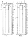
- Said sensors are connected by means of cables 7 to an electronic circuit 8 for controlling and managing said sensors, which is in turn connected by means of cables 9 to a connector 10 which is located in an original manner inside the second channel 4 of the door, in accordance with that shown in Figure 1.
- the ribs 5 act as support and seat for the electronic circuit 8.
- the connector 10 is coupled to a corresponding connector 12 represented by a component fastened to the fixed frame of the door.
- This component which is also known, has the function of supplying power to the electronic circuit 8 and hence the sensors 6 whenever the door reaches the end of its opening or closing travel path in accordance with a known technique.
- the cables 9 connect the electronic circuit 8 directly to a power source associated with the fixed frame of the doorway or the cage.
- the original feature of the present door lies in the particular configuration thereof which allows the sensors 6 and the connector 10 and the electronic circuit 8 to be housed without requiring an additional member for the sensors or a special box-shaped housing for the electronic circuit 8.
Landscapes
- Elevator Door Apparatuses (AREA)
- Power-Operated Mechanisms For Wings (AREA)
- Forklifts And Lifting Vehicles (AREA)
- Load-Engaging Elements For Cranes (AREA)
- Lift-Guide Devices, And Elevator Ropes And Cables (AREA)
- Lock And Its Accessories (AREA)
Description
- Figures 1 and 2 show a front view of the door according to two different embodiments of the connections of the anti-closing safety device;
- Figure 3 shows a cross-section along the line A-A of the door according to Figure 1;
- Figure 4 shows a cross-section through the door, the same as that of Figure 3, according to a variation of embodiment which envisages a substantially symmetrical profile of the door.
Claims (6)
- Door (1) for lifts and elevators, of the type for doorways provided with electronic anti-closing safety means comprising at least a first main component (12) associated with the fixed structure of the doorway and at least one second component (6, 8, 10) associated with one or more doors and hence movable with respect to the fixed first main component (12), in which said first and second components are not necessarily connected together by means of cables (7, 9) and the second component (6, 8, 10) draws power from the first component (12), in a continuous manner if they are connected by means of cables or in a discontinuous manner whenever the door, at the end of the opening or closing travel movement, couples together the first and second components if they are not connected by means of cables, characterized in that the door (1) is configured so as to have seats (3, 4, 5) inside which said at least one second component (6, 8, 10), is incorporated without the presence of special members or box-shaped housings.
- Door according to Claim 1, in which said seats comprise:a first channel (3) formed by the profile (2) of the door (1);ribs (5) for reinforcing the door (1);a second channel (4) formed by the profile (2) of the door (1).
- Door according to Claim 2, in which the first channel (3) and the second channel (4) are positioned on the two opposite vertical longitudinal sides of the door (1).
- Door according to Claim 2, in which the first channel (3) and the second channel (4) are opposite and identical to one another so that the door is symmetrical and may be reversibly mounted as a right-hand or left-hand door.
- Door according to Claim 2, in which the second component comprises a plurality of sensors (6) housed in the first channel (3), an electronic circuit (8) for controlling said sensors, which is housed inside the ribs (5), a connector (10) positioned inside the second channel (4), and cables (7,9) for connecting together electronic circuit (8) and sensors (6) and electronic circuit (8) and connector (10).
- Lift or elevator, characterized in that it comprises one or more doors according to any one of the preceding claims.
Applications Claiming Priority (3)
| Application Number | Priority Date | Filing Date | Title |
|---|---|---|---|
| IT1998PR000006A IT1306031B1 (en) | 1998-02-06 | 1998-02-06 | LEAF FOR LIFTS AND ELEVATORS |
| ITPR980006 | 1998-02-06 | ||
| PCT/IT1998/000306 WO1999040017A1 (en) | 1998-02-06 | 1998-10-30 | Door for lifts and elevators |
Publications (2)
| Publication Number | Publication Date |
|---|---|
| EP1053205A1 EP1053205A1 (en) | 2000-11-22 |
| EP1053205B1 true EP1053205B1 (en) | 2002-06-05 |
Family
ID=11396157
Family Applications (1)
| Application Number | Title | Priority Date | Filing Date |
|---|---|---|---|
| EP98951680A Expired - Lifetime EP1053205B1 (en) | 1998-02-06 | 1998-10-30 | Door for lifts and elevators |
Country Status (10)
| Country | Link |
|---|---|
| EP (1) | EP1053205B1 (en) |
| KR (1) | KR20010032456A (en) |
| CN (1) | CN1107018C (en) |
| AU (1) | AU9761398A (en) |
| DE (1) | DE69805856T2 (en) |
| ES (1) | ES2177074T3 (en) |
| IL (1) | IL135490A (en) |
| IT (1) | IT1306031B1 (en) |
| TR (1) | TR200002244T2 (en) |
| WO (1) | WO1999040017A1 (en) |
Families Citing this family (1)
| Publication number | Priority date | Publication date | Assignee | Title |
|---|---|---|---|---|
| ES2989023T3 (en) * | 2021-09-07 | 2024-11-25 | Wittur Holding Gmbh | Sheet metal base panel for use in elevators |
Family Cites Families (4)
| Publication number | Priority date | Publication date | Assignee | Title |
|---|---|---|---|---|
| US5149921A (en) * | 1991-07-10 | 1992-09-22 | Innovation Industries, Inc. | Self correcting infrared intrusion detection system |
| US5394961A (en) * | 1993-04-29 | 1995-03-07 | Montgomery Elevator Company | Safety edge assembly for elevator doorways |
| JPH07247084A (en) * | 1994-03-09 | 1995-09-26 | Mitsubishi Denki Bill Techno Service Kk | Safety device for elevator |
| JPH07267557A (en) * | 1994-03-29 | 1995-10-17 | Mitsubishi Denki Bill Techno Service Kk | Get-on/get-off sensing device for elevator car |
-
1998
- 1998-02-06 IT IT1998PR000006A patent/IT1306031B1/en active
- 1998-10-30 CN CN98811705A patent/CN1107018C/en not_active Expired - Fee Related
- 1998-10-30 EP EP98951680A patent/EP1053205B1/en not_active Expired - Lifetime
- 1998-10-30 DE DE69805856T patent/DE69805856T2/en not_active Expired - Fee Related
- 1998-10-30 ES ES98951680T patent/ES2177074T3/en not_active Expired - Lifetime
- 1998-10-30 AU AU97613/98A patent/AU9761398A/en not_active Abandoned
- 1998-10-30 WO PCT/IT1998/000306 patent/WO1999040017A1/en not_active Ceased
- 1998-10-30 TR TR2000/02244T patent/TR200002244T2/en unknown
- 1998-10-30 KR KR1020007005697A patent/KR20010032456A/en not_active Abandoned
- 1998-10-30 IL IL13549098A patent/IL135490A/en active IP Right Grant
Also Published As
| Publication number | Publication date |
|---|---|
| DE69805856T2 (en) | 2003-01-16 |
| ES2177074T3 (en) | 2002-12-01 |
| DE69805856D1 (en) | 2002-07-11 |
| IL135490A (en) | 2004-05-12 |
| CN1107018C (en) | 2003-04-30 |
| EP1053205A1 (en) | 2000-11-22 |
| TR200002244T2 (en) | 2000-11-21 |
| AU9761398A (en) | 1999-08-23 |
| KR20010032456A (en) | 2001-04-25 |
| IL135490A0 (en) | 2001-05-20 |
| ITPR980006A1 (en) | 1999-08-06 |
| WO1999040017A1 (en) | 1999-08-12 |
| IT1306031B1 (en) | 2001-05-29 |
| CN1280548A (en) | 2001-01-17 |
Similar Documents
| Publication | Publication Date | Title |
|---|---|---|
| EP1243544B2 (en) | Safety system for elevator doors | |
| DE69926707T2 (en) | Control device for the opening of a door | |
| US5581944A (en) | Electrical link and sensor system for automatic sliding doors | |
| CN1251957C (en) | Safety device for elevator doors | |
| US6555978B1 (en) | Automobile anti-pinching systems | |
| US20080179505A1 (en) | Multi-Optical Axis Photoelectric Sensor | |
| US8443866B2 (en) | Methods, apparatuses, and systems for movable partitions | |
| US11220855B2 (en) | Safety door switch | |
| JP2012502207A (en) | Drive system for doorway | |
| JP2009051615A (en) | Elevator device | |
| WO1999040017A1 (en) | Door for lifts and elevators | |
| US20150075074A1 (en) | Arrangement | |
| KR101912646B1 (en) | Access control of the residence | |
| KR102245816B1 (en) | Protection switch for a elevator | |
| US8002087B2 (en) | Entrance/exit device for elevator | |
| US4645037A (en) | Elevator escape structure | |
| CN114086489B (en) | Intelligent electric movable roadblock | |
| WO2016086256A1 (en) | Mobile shelving system with releasably coupleable rows | |
| US20050151066A1 (en) | Safety device for garage door | |
| CA1265069A (en) | Elevator escape structure | |
| EP1739265A2 (en) | Control apparatus for automatic opening systems | |
| DE69218172T2 (en) | Light beam detector for door openers using optical fibers | |
| KR102119620B1 (en) | Protection switch for a elevator | |
| JPH11310375A (en) | Elevator door safety device | |
| KR200257571Y1 (en) | Elevator wiring device |
Legal Events
| Date | Code | Title | Description |
|---|---|---|---|
| PUAI | Public reference made under article 153(3) epc to a published international application that has entered the european phase |
Free format text: ORIGINAL CODE: 0009012 |
|
| 17P | Request for examination filed |
Effective date: 20000330 |
|
| AK | Designated contracting states |
Kind code of ref document: A1 Designated state(s): CH DE ES FI FR GB IT LI |
|
| GRAG | Despatch of communication of intention to grant |
Free format text: ORIGINAL CODE: EPIDOS AGRA |
|
| GRAG | Despatch of communication of intention to grant |
Free format text: ORIGINAL CODE: EPIDOS AGRA |
|
| GRAH | Despatch of communication of intention to grant a patent |
Free format text: ORIGINAL CODE: EPIDOS IGRA |
|
| 17Q | First examination report despatched |
Effective date: 20011017 |
|
| GRAH | Despatch of communication of intention to grant a patent |
Free format text: ORIGINAL CODE: EPIDOS IGRA |
|
| GRAA | (expected) grant |
Free format text: ORIGINAL CODE: 0009210 |
|
| RAP1 | Party data changed (applicant data changed or rights of an application transferred) |
Owner name: WITTUR S.P.A. |
|
| AK | Designated contracting states |
Kind code of ref document: B1 Designated state(s): CH DE ES FI FR GB IT LI |
|
| REG | Reference to a national code |
Ref country code: GB Ref legal event code: FG4D |
|
| REG | Reference to a national code |
Ref country code: CH Ref legal event code: EP |
|
| REF | Corresponds to: |
Ref document number: 69805856 Country of ref document: DE Date of ref document: 20020711 |
|
| REG | Reference to a national code |
Ref country code: CH Ref legal event code: NV Representative=s name: BUGNION S.A. |
|
| ET | Fr: translation filed | ||
| REG | Reference to a national code |
Ref country code: ES Ref legal event code: FG2A Ref document number: 2177074 Country of ref document: ES Kind code of ref document: T3 |
|
| PLBE | No opposition filed within time limit |
Free format text: ORIGINAL CODE: 0009261 |
|
| STAA | Information on the status of an ep patent application or granted ep patent |
Free format text: STATUS: NO OPPOSITION FILED WITHIN TIME LIMIT |
|
| 26N | No opposition filed |
Effective date: 20030306 |
|
| PGFP | Annual fee paid to national office [announced via postgrant information from national office to epo] |
Ref country code: FR Payment date: 20041008 Year of fee payment: 7 |
|
| PGFP | Annual fee paid to national office [announced via postgrant information from national office to epo] |
Ref country code: FI Payment date: 20041014 Year of fee payment: 7 |
|
| PGFP | Annual fee paid to national office [announced via postgrant information from national office to epo] |
Ref country code: GB Payment date: 20041027 Year of fee payment: 7 Ref country code: CH Payment date: 20041027 Year of fee payment: 7 |
|
| PGFP | Annual fee paid to national office [announced via postgrant information from national office to epo] |
Ref country code: DE Payment date: 20041028 Year of fee payment: 7 |
|
| PGFP | Annual fee paid to national office [announced via postgrant information from national office to epo] |
Ref country code: ES Payment date: 20041116 Year of fee payment: 7 |
|
| PG25 | Lapsed in a contracting state [announced via postgrant information from national office to epo] |
Ref country code: GB Free format text: LAPSE BECAUSE OF NON-PAYMENT OF DUE FEES Effective date: 20051030 Ref country code: FI Free format text: LAPSE BECAUSE OF NON-PAYMENT OF DUE FEES Effective date: 20051030 |
|
| PG25 | Lapsed in a contracting state [announced via postgrant information from national office to epo] |
Ref country code: LI Free format text: LAPSE BECAUSE OF NON-PAYMENT OF DUE FEES Effective date: 20051031 Ref country code: ES Free format text: LAPSE BECAUSE OF NON-PAYMENT OF DUE FEES Effective date: 20051031 Ref country code: CH Free format text: LAPSE BECAUSE OF NON-PAYMENT OF DUE FEES Effective date: 20051031 |
|
| PG25 | Lapsed in a contracting state [announced via postgrant information from national office to epo] |
Ref country code: DE Free format text: LAPSE BECAUSE OF NON-PAYMENT OF DUE FEES Effective date: 20060503 |
|
| REG | Reference to a national code |
Ref country code: CH Ref legal event code: PL |
|
| GBPC | Gb: european patent ceased through non-payment of renewal fee |
Effective date: 20051030 |
|
| PG25 | Lapsed in a contracting state [announced via postgrant information from national office to epo] |
Ref country code: FR Free format text: LAPSE BECAUSE OF NON-PAYMENT OF DUE FEES Effective date: 20060630 |
|
| REG | Reference to a national code |
Ref country code: FR Ref legal event code: ST Effective date: 20060630 |
|
| REG | Reference to a national code |
Ref country code: ES Ref legal event code: FD2A Effective date: 20051031 |
|
| PGFP | Annual fee paid to national office [announced via postgrant information from national office to epo] |
Ref country code: IT Payment date: 20171026 Year of fee payment: 20 |