EP1052478A2 - Flache Vibrationskreisel - Google Patents
Flache Vibrationskreisel Download PDFInfo
- Publication number
- EP1052478A2 EP1052478A2 EP00109945A EP00109945A EP1052478A2 EP 1052478 A2 EP1052478 A2 EP 1052478A2 EP 00109945 A EP00109945 A EP 00109945A EP 00109945 A EP00109945 A EP 00109945A EP 1052478 A2 EP1052478 A2 EP 1052478A2
- Authority
- EP
- European Patent Office
- Prior art keywords
- plate
- gyroscope
- beams
- vibratory
- frame
- Prior art date
- Legal status (The legal status is an assumption and is not a legal conclusion. Google has not performed a legal analysis and makes no representation as to the accuracy of the status listed.)
- Granted
Links
Images


Classifications
-
- G—PHYSICS
- G01—MEASURING; TESTING
- G01C—MEASURING DISTANCES, LEVELS OR BEARINGS; SURVEYING; NAVIGATION; GYROSCOPIC INSTRUMENTS; PHOTOGRAMMETRY OR VIDEOGRAMMETRY
- G01C19/00—Gyroscopes; Turn-sensitive devices using vibrating masses; Turn-sensitive devices without moving masses; Measuring angular rate using gyroscopic effects
- G01C19/56—Turn-sensitive devices using vibrating masses, e.g. vibratory angular rate sensors based on Coriolis forces
- G01C19/5719—Turn-sensitive devices using vibrating masses, e.g. vibratory angular rate sensors based on Coriolis forces using planar vibrating masses driven in a translation vibration along an axis
Definitions
- the present invention relates generally to gyroscopes and more particularly to vibratory gyroscopes.
- Gyroscopes are devices which can sense angular rotation and/or rotation rate. Accordingly, they are useful in situations (e.g., satellite attitude control) where observation of other inertial indicators (e.g., cosmic bodies such as the sun) is temporarily obscured.
- inertial indicators e.g., cosmic bodies such as the sun
- gyroscopes based upon gimballed spinning wheels and gyroscopes based upon laser rings have been shown to be highly accurate. Although these devices find use in numerous applications (e.g., inertial navigation), their high expense and large size discourage a wider use.
- the concept of vibratory gyroscopes is based on rotation-induced energy exchange between modes of vibrating members. This concept is exemplified by an analysis of ringing wine glasses that was performed in 1890 by G. H. Bryan. In a flexural mode, the lip of a wine glass vibrates in elliptical-shaped modes that have two nodal diameters. When the wine glass is rotated, Bryan found that the node lines lag behind (precess) the rotation of the wine glass (e.g., during a 90° rotation, the node lines were observed to precess by ⁇ 27°). This nodal lag is, therefore, an indication of angular rotation.
- planar vibratory gyroscopes In contrast to these vibratory gyroscope types, the cost and size of planar vibratory gyroscopes is relatively low because they are mechanically simple (e.g., there is an absence of rotating parts) and their design typically facilitates miniaturization and batch fabrication with micromachining techniques. In addition, the precision of micromachining has enabled many vibratory gyroscopes to achieve impressive accuracy.
- One conventional planar vibratory gyroscope employs a vibrating ring as its sensing element (e.g., see Johnson, Jack D., et al., "Surface Micromachined Angular Rate Sensor", 1995 SAE Conference Paper 950538 , pp 77-83).
- This ring element can be considered to be a slice out of Bryan's wine glass.
- the ring assumes an elliptical pattern in which four nodes on the ring have no deflection and four antinodes on the ring are each located between a pair of nodes and exhibit maximal radial deflection.
- the angular position of the nodes lags the angular position to which the gyroscope is rotated.
- Another planar vibratory gyroscope is typically referred to as a clover-leaf gyroscope (e.g., see Tang, Tony K., et al., "Silicon Bulk Micromachined Vibratory Gyroscope", 1996 Solid-State Sensor and Actuator Workshop , Hilton Head, South Carolina, June 2-6) because it has a planar member whose outline resembles a four leaf clover. This member is suspended by four thin wires or beams from a housing and a metal post is coupled to the center of the member with an orientation orthogonal to the member's plane. The thin clover leaves provide large areas for electrostatic driving and capacitive sensing.
- the resonator is electrostatically excited in a control mode to rotate about a first axis of the planar member which causes the post to move in a second axis of the planar member that is orthogonal to the first axis.
- the motion of the oscillating post is displaced into movement along the first axis.
- This post displacement translates into a sense mode rotation of the planar member about the second axis.
- the post couples energy between the control and sense modes.
- planar vibratory gyroscopes described above can be miniaturized and can be generally realized with low-cost micromachining techniques, they suffer from various operational defects.
- the ring gyroscope is planar and symmetric but the sensitivity of its control and sense electrodes is degraded because of the small electrode size required to couple to the ring's flexing perimeter.
- the ring gyroscope's circular form degrades the precision with which it can be defined in bulk crystalline material by photographic masks.
- the orthogonally mounted post of the clover-leaf gyroscope detracts from its otherwise planar configuration. The post requires a manual assembly procedure which typically degrades the gyroscope's symmetry.
- this gyroscope's narrow beam supports are a source of high stress and nonlinearity.
- the present invention is directed to a planar vibratory gyroscope structure which is inherently symmetric, facilitates the use of simple monolithic fabrication processes and enables the use of sensitive control and sense systems.
- planar gyroscopic member which has a frame, a plate that is positioned within the frame and has a plate perimeter and a plurality of elongate beams which are oriented to substantially surround the plate perimeter and arranged to be everywhere substantially equidistant from the plate perimeter.
- planar member forms a system of slots and each of the slots is at least partially interleaved between adjacent ones of the slots so to define beams which each have a first end coupled to the frame and a second end coupled to the plate and proximate to the first end of an adjacent beam.
- the plate is particularly suited for vibration modes about second ends of nonadjacent beams. Because of its structural symmetry, these modes are substantially uncoupled, have substantially equal natural frequencies and the natural frequencies substantially track each other over temperature. The equal natural frequencies enhance the planar member's sensitivity to rotation and the lack of coupling reduces its sensitivity to spurious vibrations.
- the plate With the exterior rim of the planar member supported by a substrate, the plate is easily accessed with mode control and sense systems.
- the large area of the plate enhances the size of control and sense electrodes that are positioned proximate to the plate for excitation of controlled vibration modes and sensing of rotation-induced vibration modes.
- Other conventional position-sensing systems e.g., tunneling tips
- the structure of the planar member provides robust support beams which facilitate a low torsional-stress design.
- planar member facilitates its definition with precise photolithographic processes and subsequent low-cost fabrication (e.g., from crystalline materials such as silicon).
- a rectilinear embodiment of the planar member is especially suited for easy definition and fabrication, the teachings of the invention can be extended to other spatial realizations, e.g., a circular embodiment.
- Gyroscopes formed with planar members of the invention are suited for various operational modes.
- a "whole angle” mode drive signals are applied to control electrodes to initiate a vibration about an initial axis.
- Rotation of the gyroscope induces, via Coriolis coupling, a small vibration about an axis that is orthogonal to the initial axis; it is therefore, a small precession of the driven vibration.
- Sense electrodes generate signals that are indicative of the rotation-induced precession.
- the signals from the sense electrodes are fed back to the control electrodes to substantially cancel the rotation-induced precession.
- the feedback signal is a measure of the instantaneous rotation rate.
- an "open loop” mode the rotation-induced vibration amplitude about an axis orthogonal to the drive direction is sensed as a measure of rotation rate.
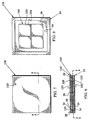
- FIGS. 1-4 A planar vibratory gyroscope 20 is illustrated in FIGS. 1-4.
- the gyroscope features a planar vibratory member 22 which is inherently symmetric, which facilitates the use of simple monolithic fabrication processes and which enables the use of sensitive control and sense systems.
- the gyroscope 20 includes a substrate 24 which carries the planar member 22.
- the planar member 22 has a frame 26, a plate 28 which extends laterally to a plate perimeter 30 and four elongate beams 32 which couple the plate 28 to the frame 26.
- the beams 32 are oriented to substantially surround the plate 28 with each of the beams 32 arranged proximate to and everywhere substantially equidistant from the plate perimeter 30 (e.g., the beam 32A lies equidistant from the perimeter portion 30A).
- the substrate 24 has a raised rim 34 which surrounds a face 36.
- its frame 26 abuts and is preferably bonded to the rim 34.
- the gyroscope 20 has a control electrode system 40 which includes four coplanar control electrodes 41.
- the gyroscope also has a vibration sensing system in the form of a sense electrode system 42 which includes four coplanar sense electrodes 43.
- the control electrode system 40 and the sense electrode system 42 are arranged in a coplanar relationship and positioned between the plate 28 and the substrate 24.
- Each of the control electrodes 41 and the sense electrodes 43 have a triangular shape.
- the control electrodes 41 are grouped together so that their outer edges 46 define a square shape.
- the sense electrodes 43 are grouped about the square shape of the control electrodes 41 so that their outer edges 48 define another and larger square shape.
- the outer edges 48 preferably lie directly below the plate perimeter 30.
- the enlarged view of FIG. 4 shows that a conductive sheet 50 covers the underside of the plate 28 so that this conductive sheet 50 is spaced directly above the control and sense electrode systems 40 and 42.
- the planar member 22 can be economically fabricated because it forms a system 59 of slots which are arranged to define the frame 26, the plate 28 and the elongate beams 32.
- Each of the slots is partially interleaved with two adjacent slots.
- the slot 60B is positioned partially outside of adjacent slot 60A and partially inside of adjacent slot 60C.
- Each of the elongate beams 32 are configured to have a first end 62 that is coupled to the frame 26 and a second end 64 that is coupled to the plate 28.
- the elongate beams 32 are oriented so that the second end 64 of each beam is proximate to the first end 62 of an adjacent beam 32.
- the plate perimeter 30 is substantially formed by inner portions 60I of each slot.
- Imaginary extension lines 66 (shown in broken lines in FIG. 1) of these inner portions indicate the plate perimeter 30 in the areas where the beam second ends 64 couple to the plate 28.
- the planar member 22 and the substrate 24 are both formed of silicon.
- the locations of the slots 60 and the face 36 can be defined with conventional photolithographic techniques and formed by conventional etching techniques.
- FIG. 5 To enhance a description of an exemplary operation process of the gyroscope, it is helpful in FIG. 5 to assign reference numbers 41A, 41B, 41C and 41D to the control electrodes and 43A, 43B, 43C and 43D to the sense electrodes. It is also helpful to define an orthogonal coordinate system 70 which has orthogonal axes 71, 72 and 73 (axes 71 and 72 are coplanar with the planar member 22 and the axis 73 is orthogonal to the planar member 22).
- the spatial arrangement of the plate 28 and the beams 32 causes the plate 28 to be suited for a first vibration about the axis 71 (i.e., about second ends 64A and 64C of nonadjacent beams 32) and a second vibration about the axis 72 (i.e., about second ends 64B and 64D of nonadjacent beams 32).
- these vibration modes are substantially uncoupled, i.e., if the plate 28 is excited into a vibration about the axis 71 and the gyroscope is not physically rotated, substantially none of the vibration energy will be diverted into a vibration about the axis 72.
- This uncoupled feature of the gyroscope 20 reduces its sensitivity to spurious inputs (e.g., external vibration).
- the symmetry of the planar member 22 also causes the natural vibration frequencies about the first and second axes 71 and 72 to be substantially matched. If a gyroscope's modes have different vibration frequencies, energy exchange is discouraged which means the gyroscope's rotation sensitivity is degraded. Accordingly, the high degree of matching of natural vibration frequencies found in the gyroscope 20 enhances its sensitivity.
- the conductive sheet (50 in FIG. 4) on the bottom of the plate 28 forms a capacitor with each of the sense electrodes 43A-D.
- the capacitance of these capacitors changes as the plate vibrates about the axes 71 and 72 and this capacitance change can be sensed in any conventional capacitance-sensitive circuit (e.g., a resonant circuit).
- a capacitance-sensitive circuit e.g., a resonant circuit.
- vibration of the plate 28 about the axis 71 is sensed as capacitance changes that involve the electrodes 43A and 43C.
- vibration of the plate 28 about the axis 72 is sensed as capacitance changes that involve the electrodes 43B and 43D.
- the positions of the control and sense electrode systems may be interchanged, positioning the sense electrodes 43 near the plate's perimeter (30 in FIG. 1) enhances the sensing sensitivity.
- the plate 28 can be attracted to and repelled from each electrode in a controlled manner (to effect this action, the conductive sheet can be coupled through a sheet extension to a potential such as ground).
- a potential such as ground
- application of alternating voltages to the control electrodes 41A and 41C will excite a vibration of the plate 28 about the axis 71. In the absence of physical rotation of the gyroscope 20, essentially none of this vibration energy will be coupled into vibration about the axis 72 because of the uncoupled nature of the plate 28.
- the plate 28 is freely vibrating about the axis 71 and the gyroscope 20 is rotated about the axis 73, some of the energy will be converted by precession into a vibration about the axis 72.
- the altered vibration amplitude about the axis 71 is sensed through sense electrodes 43A and 43C and the altered vibration amplitude about the axis 72 is sensed through sense electrodes 43B and 43D.
- a combination of these sensed amplitudes is indicative of the precession angle and, hence, of the rotation angle through which the gyroscope was rotated.
- the above-described operational process of the gyroscope 20 is conventionally referred to as a "whole angle" operational mode. In this mode, vibration amplitude may be sustained, without disturbing orientation of the vibrating pattern (i.e., without inducing erroneous precession), by application of drive voltage to all electrodes at twice the vibration frequency.
- FIG. 6 is a schematized view of a gyroscope system 80 in which elements of the gyroscope 20 of FIGS. 1-5 are separated to enhance a further understanding of the gyroscope's operation.
- the drive electrode system 40 and the sense electrode system 42 have been spaced on opposite sides of the planar member 22 to facilitate descriptions of gyroscopic operational processes.
- the signal of a voltage generator 82 is applied differentially (indicated by inverter 81) to opposed electrodes of the control electrode system 40 to thereby control vibration of the plate 28 about a control axis 71.
- the output from a switch 90 is applied differentially (indicated by inverter 85) to opposed electrodes of the control electrode system so as to control vibration of the plate 28 about a sense axis 72.
- a switch 90 is placed in an open position to deactivate the feedback loop 94.
- a vibration is induced in the plate 28 about the control axis 71.
- the gyroscope is rotated about the axis 73 of FIG. 5, energy is transferred to a rotation-induced vibration whose rotation-induced axis is orthogonal to the controlled vibration axis.
- Signals indicative of the rotation-induced vibration are generated by the sense electrode system 42 and coupled through a signal processor 83 to an output port 86.
- the signal processor 83 performs necessary signal operations (e.g., capacitance to voltage conversion and vector combination of signals from different pairs of electrodes of the sense electrode system 42) to generate a desired signal form at the output port 86.
- This output signal is the open loop indication of the gyroscope's rotation angle.
- the switch 90 is closed and the output of the signal processor 83 is coupled to the drive electrode system 40.
- the amplitude of the processor signal may be adjusted, e.g., through an amplifier 84. If the gain of the feedback loop 94 is sufficiently high, precession in the planar member 22 of rotation-induced vibration is substantially canceled and the output signal at the output port 86 is therefore indicative of the instantaneous rotation rate. In FIG. 6, therefore, the switch 90 is used to select between open loop and force to rebalance operational processes.
- the signals of the voltage generator 82 and the feedback loop 94 are applied to opposite electrodes to effect vibration modes about the axes 71 and 72.
- the voltage generator's signal can be applied to one adjacent pair of electrodes and the feedback loop's signal applied to the other adjacent pair. This will effect a 45° rotation of the axes 71 and 72.
- FIGS. 7-9 illustrate another vibratory gyroscope embodiment 100 of the present invention. These views are similar to FIGS. 1-3 with like elements represented by like reference numbers.
- the gyroscope 100 has a control electrode system 102 that includes control electrodes 103.
- the latter control electrodes have a square shape, are positioned proximate to one side of the planar member 22 and are arranged so that their outer edges 104 lie directly below the plate perimeter (30 in FIG. 1).
- the gyroscope 100 has a sense electrode system 106 in which sense electrodes 107 have a square shape, are positioned proximate to an opposite side of the planar member 22 and are arranged so that their outer edges lie directly above the plate perimeter.
- the planar member's frame 26 abuts the rim 34 of a substrate 24.
- a second substrate 110 extends over and protects the sense electrode system 106.
- the second substrate 110 is similar to the substrate 24 and a rim 112 of the second substrate abuts and is preferably bonded to another side of the planar member's frame 26.
- the gyroscope 100 is more sensitive than the gyroscope 20 but the additional sensitivity is gained at the cost of increased size and complexity.
- the vibratory planar member 22 of FIGS. 1 and 2 represents a rectilinear embodiment of the invention's teachings. These teachings may be extended to various other embodiments.
- a circular embodiment 122 is illustrated in FIG. 10.
- the planar member 122 has a hollow frame 126, a plate 128 which extends laterally to a plate perimeter 130 and four elongate beams 132 which couple the plate 128 to the frame 126.
- the beams 132 are oriented to substantially surround the plate 128 and each beam 132 is arranged to be everywhere substantially equidistant from the plate perimeter 130 (e.g., the beam 132A lies equidistant from the perimeter portion 130A).
- planar member 122 can be fabricated with the aid of a system 139 of slots 140 which are arranged to define the frame 126, the plate 128 and the elongate beams 132 which each have a first end 142 and a second end 144.
- Each of the slots 140 is partially interleaved with two adjacent slots and is configured so that the second end 144 of each beam is proximate to the first end 142 of an adjacent beam 132.
- the plate perimeter 130 is substantially formed by inner portions 140I of each slot.
- a position-sensing system in the form of a sense electrode system 42 was used for sensing rotation-induced vibration modes.
- the gyroscope 120 of FIGS. 7-9 used a different sense electrode system 106.
- Other conventional position-sensing systems can be substituted to form still other gyroscope embodiments.
- FIG. 11A illustrates a position-sensing system in the form of a tunneling tip 160 whose probe tip 162 is carried by a translation driver in the form of a piezoelectric transducer 164.
- the transducer 164 moves the probe tip 162 so as to maintain it in close proximity with the plate 28 to generate a measurable tip-to-plate interaction.
- An electrical potential is imposed across a tip-to-plate gap 165 and this potential causes tip and plate electrons to form a tunneling current 166 whose magnitude is extremely sensitive to the dimension of the gap 165.
- a control loop responds to the tunneling current 166 by applying a control signal 168 to the transducer 164.
- the transducer vertically translates the probe tip 162 to maintain a constant tunneling current 166.
- the control signal 168 is, therefore, an accurate indicator of the position of the plate 28.
- FIG. 11A There are numerous variations of the tunneling tip 160 of FIG. 11A.
- One is the tip structure 170 shown in FIG. 11B.
- a tip probe 172 is coupled by a resilient cantilever 174 to a translation driver 175.
- a laser 176 emits a laser beam 177 which is reflected from the cantilever 174 and received by a detector 178.
- the output signal of the detector 178 is, therefore, a function of the cantilever's deflection.
- a control loop applies a control signal 179 to the translation driver 175 to maintain a constant detector signal and, hence, a constant cantilever deflection.
- the control signal 179 is, therefore, an accurate indicator of the position of the plate 28.
- FIGS. 12A and 12B are schematics of the control and sense electrode systems of FIG. 5 taken along an exemplary x axis (axis 71 in FIG. 5).
- FIG. 12A shows the sense electrodes 43A and 43C that sense rotation about the x axis
- FIG. 12B shows the control electrodes 41A and 41C that control rotation about the x axis.
- Electrode voltages along the y axis that are equivalent to those of FIG. 12A are V 3s and V 4s and equivalent voltages to those of FIG. 12B are V 3c and V 4c .
- the electrodes have an area A, the centroids of the control electrodes are radially offset by r c and the centroids of the sense electrodes are radially offset by r s .
- Sense voltages that are generated in FIG. 12A are approximately proportional to plate rotation ⁇ x about the x and y axes (axes 71 and 72 in FIG. 5) and the axial translation z.
- the sense voltages are expressed as:
- the torques about the x and y axes are proportional respectively to V xc and V yc ., i.e.,
- its associated beams can be thinned by etching from one or both sides of the plate.
- ⁇ x ⁇ o ⁇ x cos( ⁇ x t ) and ⁇ y ⁇ ⁇ y ⁇ 0. respectively, which produces It is noted that the angular gain approaches 0 for very thin plates and is 1/2 for a plate in the shape of a cube.
- the demodulated control voltage is, wherein the overbar indicates a baseband signal.
- the demodulated sense voltage is: in which ⁇ o is the sense mode phase shift at the drive frequency.
- Q t is the tuning gain between the control and sense modes
- the equivalent Brownian noise rate noise ⁇ nB is and the equivalent electronic rate noise ⁇ ne is
- Q m 50,000 (typical for crystal silicon in vacuum) applied voltages
- Q t 100.
- Performance of planar gyroscopes is degraded by the presence of noise signals, e.g., electronic noise and Brownian (thermal) noise.
- electronic noise is reduced by increasing the width of the plate 28 and Brownian noise is generally reduced by increasing the plate's thickness.
- a thinner plate will reduce the manufacturing time required to etch the plate's slot system 59.
- Table 200 of FIG. 13 illustrates selected values for same of these parameters in three exemplary designs of the gyroscope embodiments of the present invention.
- a gyroscopic angle random walk of ⁇ 0.03°/ ⁇ hour is typically required.
- Design 1 in table 200 for example, has a thin plate which achieves this requirement.
- this design can be realized at a cost of ⁇ 100 dollars/wafer with polished silicon wafers having a thickness of ⁇ 400 micrometers. It is further estimated that more than 1000 planar members can be batch fabricated and packaged using three six-inch wafers in ⁇ 2 hours based on an ion etch rate of ⁇ 3 micrometers/hour. Designs 2 and 3 gain improved performance with thicker and wider plates and thicker beams.
- planar members of the invention have been shown to have four beams of similar cross section, the teachings of the invention can be extended to configurations that have different numbers of beams and beams that have different cross sections.
- the beams have been shown and described as being coplanar with the plate (e.g., the beams 32 and the plate 28 of FIG. 2). Although this configuration may facilitate fabrication of the invention, nonplanar embodiments may also find utility when practicing the teachings of the invention.
- the conductive sheet 50 of FIG. 4 can be applied with various conventional materials and processes (e.g., silicon doping). It can be coupled to ground with various conventional structures (e.g., a sheet extension or a thin wire).
Landscapes
- Physics & Mathematics (AREA)
- Engineering & Computer Science (AREA)
- General Physics & Mathematics (AREA)
- Radar, Positioning & Navigation (AREA)
- Remote Sensing (AREA)
- Gyroscopes (AREA)
Applications Claiming Priority (2)
| Application Number | Priority Date | Filing Date | Title |
|---|---|---|---|
| US310898 | 1999-05-12 | ||
| US09/310,898 US6289733B1 (en) | 1999-05-12 | 1999-05-12 | Planar vibratory gyroscopes |
Publications (3)
| Publication Number | Publication Date |
|---|---|
| EP1052478A2 true EP1052478A2 (de) | 2000-11-15 |
| EP1052478A3 EP1052478A3 (de) | 2003-08-13 |
| EP1052478B1 EP1052478B1 (de) | 2015-07-15 |
Family
ID=23204560
Family Applications (1)
| Application Number | Title | Priority Date | Filing Date |
|---|---|---|---|
| EP00109945.6A Expired - Lifetime EP1052478B1 (de) | 1999-05-12 | 2000-05-11 | Flache Vibrationskreisel |
Country Status (2)
| Country | Link |
|---|---|
| US (1) | US6289733B1 (de) |
| EP (1) | EP1052478B1 (de) |
Cited By (3)
| Publication number | Priority date | Publication date | Assignee | Title |
|---|---|---|---|---|
| WO2003071241A1 (en) | 2002-02-25 | 2003-08-28 | Sintef Elektronikk Og Kybernetikk | Spring scale |
| US7120548B2 (en) | 2002-11-20 | 2006-10-10 | Bae Systems Plc | Method of calibrating bias drift with temperature for a vibrating structure gyroscope |
| US7801694B1 (en) | 2007-09-27 | 2010-09-21 | Watson Industries, Inc. | Gyroscope with temperature compensation |
Families Citing this family (56)
| Publication number | Priority date | Publication date | Assignee | Title |
|---|---|---|---|---|
| US7170665B2 (en) * | 2002-07-24 | 2007-01-30 | Olympus Corporation | Optical unit provided with an actuator |
| US6418789B1 (en) * | 1999-02-26 | 2002-07-16 | Murata Manufacturing Co., Ltd. | Vibrating gyroscope |
| US6955084B2 (en) * | 2001-08-10 | 2005-10-18 | The Boeing Company | Isolated resonator gyroscope with compact flexures |
| US6629460B2 (en) * | 2001-08-10 | 2003-10-07 | The Boeing Company | Isolated resonator gyroscope |
| US6698287B2 (en) * | 2001-08-10 | 2004-03-02 | The Boeing Company | Microgyro tuning using focused ion beams |
| US7017410B2 (en) * | 2001-08-10 | 2006-03-28 | The Boeing Company | Isolated resonator gyroscope with a drive and sense plate |
| US6990863B2 (en) | 2001-08-10 | 2006-01-31 | The Boeing Company | Isolated resonator gyroscope with isolation trimming using a secondary element |
| US7089792B2 (en) * | 2002-02-06 | 2006-08-15 | Analod Devices, Inc. | Micromachined apparatus utilizing box suspensions |
| US6877374B2 (en) * | 2002-02-06 | 2005-04-12 | Analog Devices, Inc. | Micromachined gyroscope |
| US6823734B1 (en) * | 2002-04-26 | 2004-11-30 | California Institute Of Technology | Electrostatic spring softening in redundant degree of freedom resonators |
| US6915215B2 (en) * | 2002-06-25 | 2005-07-05 | The Boeing Company | Integrated low power digital gyro control electronics |
| US6944931B2 (en) * | 2002-08-12 | 2005-09-20 | The Boeing Company | Method of producing an integral resonator sensor and case |
| US7168318B2 (en) * | 2002-08-12 | 2007-01-30 | California Institute Of Technology | Isolated planar mesogyroscope |
| US7040163B2 (en) * | 2002-08-12 | 2006-05-09 | The Boeing Company | Isolated planar gyroscope with internal radial sensing and actuation |
| US6922118B2 (en) * | 2002-11-01 | 2005-07-26 | Hrl Laboratories, Llc | Micro electrical mechanical system (MEMS) tuning using focused ion beams |
| US7994877B1 (en) | 2008-11-10 | 2011-08-09 | Hrl Laboratories, Llc | MEMS-based quartz hybrid filters and a method of making the same |
| US8766745B1 (en) | 2007-07-25 | 2014-07-01 | Hrl Laboratories, Llc | Quartz-based disk resonator gyro with ultra-thin conductive outer electrodes and method of making same |
| US7581443B2 (en) * | 2005-07-20 | 2009-09-01 | The Boeing Company | Disc resonator gyroscopes |
| US7285844B2 (en) * | 2003-06-10 | 2007-10-23 | California Institute Of Technology | Multiple internal seal right micro-electro-mechanical system vacuum package |
| WO2005103620A1 (en) * | 2004-04-14 | 2005-11-03 | Analog Devices, Inc. | Inertial sensor with a linear array of sensor elements |
| US7437253B2 (en) * | 2004-07-29 | 2008-10-14 | The Boeing Company | Parametrically disciplined operation of a vibratory gyroscope |
| US7478557B2 (en) | 2004-10-01 | 2009-01-20 | Analog Devices, Inc. | Common centroid micromachine driver |
| US7421897B2 (en) | 2005-04-14 | 2008-09-09 | Analog Devices, Inc. | Cross-quad and vertically coupled inertial sensors |
| US7555824B2 (en) | 2006-08-09 | 2009-07-07 | Hrl Laboratories, Llc | Method for large scale integration of quartz-based devices |
| CN100439864C (zh) * | 2007-06-01 | 2008-12-03 | 北京沃尔康科技有限责任公司 | 一种新型硅微机械陀螺 |
| US10266398B1 (en) | 2007-07-25 | 2019-04-23 | Hrl Laboratories, Llc | ALD metal coatings for high Q MEMS structures |
| US7836765B2 (en) * | 2007-07-31 | 2010-11-23 | The Boeing Company | Disc resonator integral inertial measurement unit |
| US8109145B2 (en) * | 2007-07-31 | 2012-02-07 | Northrop Grumman Guidance And Electronics Company, Inc. | Micro hemispheric resonator gyro |
| US8151640B1 (en) | 2008-02-05 | 2012-04-10 | Hrl Laboratories, Llc | MEMS on-chip inertial navigation system with error correction |
| US7802356B1 (en) | 2008-02-21 | 2010-09-28 | Hrl Laboratories, Llc | Method of fabricating an ultra thin quartz resonator component |
| US8322028B2 (en) * | 2009-04-01 | 2012-12-04 | The Boeing Company | Method of producing an isolator for a microelectromechanical system (MEMS) die |
| US8393212B2 (en) | 2009-04-01 | 2013-03-12 | The Boeing Company | Environmentally robust disc resonator gyroscope |
| US8327526B2 (en) | 2009-05-27 | 2012-12-11 | The Boeing Company | Isolated active temperature regulator for vacuum packaging of a disc resonator gyroscope |
| US8176607B1 (en) | 2009-10-08 | 2012-05-15 | Hrl Laboratories, Llc | Method of fabricating quartz resonators |
| FR2958029B1 (fr) * | 2010-03-23 | 2012-04-20 | Sagem Defense Securite | Procede de mesure angulaire au moyen d'un capteur vibrant auquel sont appliquees des commandes modulees |
| US8912711B1 (en) | 2010-06-22 | 2014-12-16 | Hrl Laboratories, Llc | Thermal stress resistant resonator, and a method for fabricating same |
| US8650955B2 (en) | 2012-01-18 | 2014-02-18 | The United States Of America As Represented By The Secretary Of The Navy | Time domain switched gyroscope |
| US8875576B2 (en) | 2012-03-21 | 2014-11-04 | The United States Of America As Represented By The Secretary Of The Navy | Apparatus and method for providing an in-plane inertial device with integrated clock |
| US8991250B2 (en) | 2012-09-11 | 2015-03-31 | The United States Of America As Represented By Secretary Of The Navy | Tuning fork gyroscope time domain inertial sensor |
| US9250074B1 (en) | 2013-04-12 | 2016-02-02 | Hrl Laboratories, Llc | Resonator assembly comprising a silicon resonator and a quartz resonator |
| US9599470B1 (en) | 2013-09-11 | 2017-03-21 | Hrl Laboratories, Llc | Dielectric high Q MEMS shell gyroscope structure |
| CN103697873B (zh) * | 2013-12-13 | 2016-11-23 | 上海交通大学 | 回柱形微机械固体波动模态匹配陀螺 |
| US9977097B1 (en) | 2014-02-21 | 2018-05-22 | Hrl Laboratories, Llc | Micro-scale piezoelectric resonating magnetometer |
| US9991863B1 (en) | 2014-04-08 | 2018-06-05 | Hrl Laboratories, Llc | Rounded and curved integrated tethers for quartz resonators |
| US10308505B1 (en) | 2014-08-11 | 2019-06-04 | Hrl Laboratories, Llc | Method and apparatus for the monolithic encapsulation of a micro-scale inertial navigation sensor suite |
| JP6481293B2 (ja) | 2014-09-05 | 2019-03-13 | セイコーエプソン株式会社 | 物理量センサー素子、物理量センサー、電子機器および移動体 |
| JP6481294B2 (ja) | 2014-09-05 | 2019-03-13 | セイコーエプソン株式会社 | 物理量センサー素子、物理量センサー、電子機器および移動体 |
| JP2016057073A (ja) | 2014-09-05 | 2016-04-21 | セイコーエプソン株式会社 | 物理量センサー素子、物理量センサー、電子機器および移動体 |
| US10031191B1 (en) | 2015-01-16 | 2018-07-24 | Hrl Laboratories, Llc | Piezoelectric magnetometer capable of sensing a magnetic field in multiple vectors |
| US10110198B1 (en) | 2015-12-17 | 2018-10-23 | Hrl Laboratories, Llc | Integrated quartz MEMS tuning fork resonator/oscillator |
| US10175307B1 (en) | 2016-01-15 | 2019-01-08 | Hrl Laboratories, Llc | FM demodulation system for quartz MEMS magnetometer |
| RU2619815C1 (ru) * | 2016-05-12 | 2017-05-18 | Акционерное общество "Ижевский электромеханический завод "Купол" | Способ и система компенсации дрейфа твердотельного волнового гироскопа |
| US10696541B2 (en) | 2016-05-26 | 2020-06-30 | Honeywell International Inc. | Systems and methods for bias suppression in a non-degenerate MEMS sensor |
| US11237000B1 (en) | 2018-05-09 | 2022-02-01 | Hrl Laboratories, Llc | Disk resonator gyroscope with out-of-plane electrodes |
| US11796831B2 (en) * | 2018-12-17 | 2023-10-24 | Semiconductor Components Industries, Llc | Methods and system for position stabilization |
| RU2704334C1 (ru) * | 2019-04-02 | 2019-10-28 | Федеральное государственное бюджетное учреждение науки Институт проблем механики им. А.Ю. Ишлинского Российской академии наук | Способ считывания и управления колебаниями волнового твердотельного гироскопа |
Citations (3)
| Publication number | Priority date | Publication date | Assignee | Title |
|---|---|---|---|---|
| DE4431232A1 (de) * | 1994-09-02 | 1996-03-14 | Hahn Schickard Ges | Integrierbares Feder-Masse-System |
| US5665915A (en) * | 1992-03-25 | 1997-09-09 | Fuji Electric Co., Ltd. | Semiconductor capacitive acceleration sensor |
| US5777226A (en) * | 1994-03-28 | 1998-07-07 | I/O Sensors, Inc. | Sensor structure with L-shaped spring legs |
Family Cites Families (5)
| Publication number | Priority date | Publication date | Assignee | Title |
|---|---|---|---|---|
| DE69102590T2 (de) * | 1990-05-18 | 1994-10-06 | British Aerospace | Trägheitssensoren. |
| US5756895A (en) * | 1995-09-01 | 1998-05-26 | Hughes Aircraft Company | Tunneling-based rate gyros with simple drive and sense axis coupling |
| KR0171009B1 (ko) * | 1995-12-07 | 1999-05-01 | 양승택 | 원판 진동형 마이크로 자이로스코프 및 그의 제조방법 |
| US5894090A (en) * | 1996-05-31 | 1999-04-13 | California Institute Of Technology | Silicon bulk micromachined, symmetric, degenerate vibratorygyroscope, accelerometer and sensor and method for using the same |
| US6009751A (en) * | 1998-10-27 | 2000-01-04 | Ljung; Bo Hans Gunnar | Coriolis gyro sensor |
-
1999
- 1999-05-12 US US09/310,898 patent/US6289733B1/en not_active Expired - Lifetime
-
2000
- 2000-05-11 EP EP00109945.6A patent/EP1052478B1/de not_active Expired - Lifetime
Patent Citations (3)
| Publication number | Priority date | Publication date | Assignee | Title |
|---|---|---|---|---|
| US5665915A (en) * | 1992-03-25 | 1997-09-09 | Fuji Electric Co., Ltd. | Semiconductor capacitive acceleration sensor |
| US5777226A (en) * | 1994-03-28 | 1998-07-07 | I/O Sensors, Inc. | Sensor structure with L-shaped spring legs |
| DE4431232A1 (de) * | 1994-09-02 | 1996-03-14 | Hahn Schickard Ges | Integrierbares Feder-Masse-System |
Cited By (4)
| Publication number | Priority date | Publication date | Assignee | Title |
|---|---|---|---|---|
| WO2003071241A1 (en) | 2002-02-25 | 2003-08-28 | Sintef Elektronikk Og Kybernetikk | Spring scale |
| US7078631B2 (en) | 2002-02-25 | 2006-07-18 | Sintef Elektronikk Og Kybernetikk | Spring scale |
| US7120548B2 (en) | 2002-11-20 | 2006-10-10 | Bae Systems Plc | Method of calibrating bias drift with temperature for a vibrating structure gyroscope |
| US7801694B1 (en) | 2007-09-27 | 2010-09-21 | Watson Industries, Inc. | Gyroscope with temperature compensation |
Also Published As
| Publication number | Publication date |
|---|---|
| EP1052478A3 (de) | 2003-08-13 |
| US6289733B1 (en) | 2001-09-18 |
| EP1052478B1 (de) | 2015-07-15 |
Similar Documents
| Publication | Publication Date | Title |
|---|---|---|
| EP1052478B1 (de) | Flache Vibrationskreisel | |
| US5392650A (en) | Micromachined accelerometer gyroscope | |
| US6282958B1 (en) | Angular rate sensor | |
| US5894090A (en) | Silicon bulk micromachined, symmetric, degenerate vibratorygyroscope, accelerometer and sensor and method for using the same | |
| US7640803B1 (en) | Micro-electromechanical system inertial sensor | |
| US5915276A (en) | Rate sensor | |
| EP1415127B1 (de) | Isoliertes schwingungsgyroskop | |
| US5226321A (en) | Vibrating planar gyro | |
| US5987986A (en) | Navigation grade micromachined rotation sensor system | |
| US6481285B1 (en) | Micro-machined angle-measuring gyroscope | |
| US8056413B2 (en) | Sensor and sensing method utilizing symmetrical differential readout | |
| JP3839720B2 (ja) | 角速度センサデバイスに関する改良 | |
| WO2009061747A1 (en) | Integrated microelectromechanical systems (mems) vibrating mass z-axis rate sensor | |
| EP1606583B1 (de) | Mikrogefertigter vibrationskreisel mit elektrostatischer kupplung | |
| JPH11337345A (ja) | 振動するマイクロジャイロメータ | |
| US6990863B2 (en) | Isolated resonator gyroscope with isolation trimming using a secondary element | |
| WO2001079862A1 (en) | Z-axis micro-gyro | |
| WO1999022203A1 (en) | Multi-axis gyroscope | |
| Voss | Silicon micromachined vibrating gyroscopes | |
| KR100319920B1 (ko) | 비대칭 내부 비틀림 짐벌을 가진 측면 구동 방식의 짐벌형 자이로스코프 | |
| WO2022248647A1 (en) | Angular rate sensors | |
| WO2000006971A1 (en) | Micromachined rotation sensor with modular sensor elements |
Legal Events
| Date | Code | Title | Description |
|---|---|---|---|
| PUAI | Public reference made under article 153(3) epc to a published international application that has entered the european phase |
Free format text: ORIGINAL CODE: 0009012 |
|
| AK | Designated contracting states |
Kind code of ref document: A2 Designated state(s): AT BE CH CY DE DK ES FI FR GB GR IE IT LI LU MC NL PT SE |
|
| AX | Request for extension of the european patent |
Free format text: AL;LT;LV;MK;RO;SI |
|
| PUAL | Search report despatched |
Free format text: ORIGINAL CODE: 0009013 |
|
| AK | Designated contracting states |
Designated state(s): AT BE CH CY DE DK ES FI FR GB GR IE IT LI LU MC NL PT SE |
|
| AX | Request for extension of the european patent |
Extension state: AL LT LV MK RO SI |
|
| 17P | Request for examination filed |
Effective date: 20040115 |
|
| AKX | Designation fees paid |
Designated state(s): DE FR GB IT |
|
| 17Q | First examination report despatched |
Effective date: 20071009 |
|
| GRAP | Despatch of communication of intention to grant a patent |
Free format text: ORIGINAL CODE: EPIDOSNIGR1 |
|
| INTG | Intention to grant announced |
Effective date: 20150129 |
|
| GRAS | Grant fee paid |
Free format text: ORIGINAL CODE: EPIDOSNIGR3 |
|
| GRAA | (expected) grant |
Free format text: ORIGINAL CODE: 0009210 |
|
| AK | Designated contracting states |
Kind code of ref document: B1 Designated state(s): DE FR GB IT |
|
| REG | Reference to a national code |
Ref country code: GB Ref legal event code: FG4D |
|
| REG | Reference to a national code |
Ref country code: DE Ref legal event code: R096 Ref document number: 60049009 Country of ref document: DE |
|
| REG | Reference to a national code |
Ref country code: DE Ref legal event code: R097 Ref document number: 60049009 Country of ref document: DE |
|
| PG25 | Lapsed in a contracting state [announced via postgrant information from national office to epo] |
Ref country code: IT Free format text: LAPSE BECAUSE OF FAILURE TO SUBMIT A TRANSLATION OF THE DESCRIPTION OR TO PAY THE FEE WITHIN THE PRESCRIBED TIME-LIMIT Effective date: 20150715 |
|
| PLBE | No opposition filed within time limit |
Free format text: ORIGINAL CODE: 0009261 |
|
| STAA | Information on the status of an ep patent application or granted ep patent |
Free format text: STATUS: NO OPPOSITION FILED WITHIN TIME LIMIT |
|
| REG | Reference to a national code |
Ref country code: FR Ref legal event code: PLFP Year of fee payment: 17 |
|
| 26N | No opposition filed |
Effective date: 20160418 |
|
| REG | Reference to a national code |
Ref country code: FR Ref legal event code: PLFP Year of fee payment: 18 |
|
| REG | Reference to a national code |
Ref country code: FR Ref legal event code: PLFP Year of fee payment: 19 |
|
| PGFP | Annual fee paid to national office [announced via postgrant information from national office to epo] |
Ref country code: DE Payment date: 20190530 Year of fee payment: 20 |
|
| PGFP | Annual fee paid to national office [announced via postgrant information from national office to epo] |
Ref country code: FR Payment date: 20190527 Year of fee payment: 20 |
|
| PGFP | Annual fee paid to national office [announced via postgrant information from national office to epo] |
Ref country code: GB Payment date: 20190528 Year of fee payment: 20 |
|
| REG | Reference to a national code |
Ref country code: DE Ref legal event code: R071 Ref document number: 60049009 Country of ref document: DE |
|
| REG | Reference to a national code |
Ref country code: GB Ref legal event code: PE20 Expiry date: 20200510 |
|
| PG25 | Lapsed in a contracting state [announced via postgrant information from national office to epo] |
Ref country code: GB Free format text: LAPSE BECAUSE OF EXPIRATION OF PROTECTION Effective date: 20200510 |