EP1052156A1 - Zentriervorrichtung zur Aufnahme einer Elektrokupplung einer automatischen Zugkupplung - Google Patents
Zentriervorrichtung zur Aufnahme einer Elektrokupplung einer automatischen Zugkupplung Download PDFInfo
- Publication number
- EP1052156A1 EP1052156A1 EP00105995A EP00105995A EP1052156A1 EP 1052156 A1 EP1052156 A1 EP 1052156A1 EP 00105995 A EP00105995 A EP 00105995A EP 00105995 A EP00105995 A EP 00105995A EP 1052156 A1 EP1052156 A1 EP 1052156A1
- Authority
- EP
- European Patent Office
- Prior art keywords
- coupling
- centering device
- centering
- baffle
- section
- Prior art date
- Legal status (The legal status is an assumption and is not a legal conclusion. Google has not performed a legal analysis and makes no representation as to the accuracy of the status listed.)
- Granted
Links
- 238000010168 coupling process Methods 0.000 title claims abstract description 142
- 238000005859 coupling reaction Methods 0.000 title claims abstract description 134
- 230000008878 coupling Effects 0.000 title claims abstract description 129
- 238000000034 method Methods 0.000 claims abstract description 11
- 238000006073 displacement reaction Methods 0.000 claims description 3
- 238000003825 pressing Methods 0.000 claims description 3
- 230000000630 rising effect Effects 0.000 claims 1
- 230000006835 compression Effects 0.000 description 9
- 238000007906 compression Methods 0.000 description 9
- 230000013011 mating Effects 0.000 description 7
- 238000013016 damping Methods 0.000 description 3
- 230000015572 biosynthetic process Effects 0.000 description 1
- 210000003746 feather Anatomy 0.000 description 1
- 230000000384 rearing effect Effects 0.000 description 1
- 238000000926 separation method Methods 0.000 description 1
- 239000000725 suspension Substances 0.000 description 1
Images



Classifications
-
- B—PERFORMING OPERATIONS; TRANSPORTING
- B61—RAILWAYS
- B61G—COUPLINGS; DRAUGHT AND BUFFING APPLIANCES
- B61G5/00—Couplings for special purposes not otherwise provided for
- B61G5/06—Couplings for special purposes not otherwise provided for for, or combined with, couplings or connectors for fluid conduits or electric cables
-
- B—PERFORMING OPERATIONS; TRANSPORTING
- B61—RAILWAYS
- B61G—COUPLINGS; DRAUGHT AND BUFFING APPLIANCES
- B61G5/00—Couplings for special purposes not otherwise provided for
- B61G5/06—Couplings for special purposes not otherwise provided for for, or combined with, couplings or connectors for fluid conduits or electric cables
- B61G5/10—Couplings for special purposes not otherwise provided for for, or combined with, couplings or connectors for fluid conduits or electric cables for electric cables
Definitions
- the invention relates to a centering device for receiving an electric clutch an automatic train coupling according to the preamble of claim 1, a automatic train coupling with such a centering device and a coupling and release method for the electrical coupling of an automatic train coupling.
- Automatic train couplings enable the automated connection of two Rail vehicles, in the coupled state two such couplings one Establish a rigid connection between the vehicles.
- An automatic pull coupling has become known from EP 0501244, comprising a coupling head as well as a cable coupling with elastic at the front push-back and in the coupling state pneumatically forward, in the pressing direction to a mating line coupling head, loaded line coupling head.
- a disadvantage of the automatic train couplings with pneumatic distribution is that compressed air must always be available. For example, a car has been standing for three months in the cold, the air reservoir is emptied and propulsion accordingly not possible anymore.
- DE 43 10 741 shows an automatic train coupling with a coupling body and an electric clutch, which subsequently, i.e. after finishing mechanical Coupling, coupling.
- Such a coupling must be up to the compensation certain transverse play between the mechanical couplings only in the longitudinal direction be moved.
- the electric clutch known from DE 43 10 741 is designed such that the electrical coupling is released before mechanical uncoupling, so that due to the transverse movements forced by the mechanical coupling Longitudinal guide of the electric coupling is not damaged.
- a disadvantage of the line couplings or the electrical coupling according to the State of the art is that the coupling of the line elements or the electrical coupling either must be done mechanically or after completion of the mechanical Coupling process.
- the object of the invention is a centering device for receiving an electric clutch an automatic train coupling to indicate the disadvantages of the State of the art can be avoided, but in particular a safe and automated coupling of the electrical coupling simultaneously with the mechanical one Domes is enabled.
- the invention has a centering device for receiving such Electric coupling a guide frame, a locking and releasing device and a receiving device for the electric clutch and is characterized in that that the centering device has a height and self-centering device, so that the electrical couplings arranged in the receiving devices two consecutive pull couplings are automatically centered without the two electrical couplings in contact with each other during the centering process come.
- the height and side centering is advantageously carried out with the help of an impact surface reached, the impact surface having a first, a second and a third section has and the baffles of the first and third sections offset in parallel run to each other and the baffles of the second section with the Boundary surface of the first or third section enclose an angle 0 ⁇ ⁇ 90 °.
- angle ⁇ the impact surface of the second section with that of the first or third section, preferably in Range is 30 ⁇ ⁇ 60 °.
- Angle ⁇ 45 °
- the baffle is part of a baffle frame, which is guided by a guide frame of the centering device.
- a sufficient mobility of the impact surface and protection of the electrical coupling against Damage to the coupling process is achieved in that the centering device comprises a handlebar arrangement with a pre-pressing device, which is configured in this way is that the baffle is in a position ready for coupling before coupling Lead is held in front of the coupling level of the electric clutch.
- This lead is particularly preferably 10 to 20 cm.
- a delay device is advantageously provided which is configured in this way is that they have run-up forces that occur when the impact surfaces of the electric clutch collide arise, delay.
- a further damping can be in a special embodiment of the electric clutch at high run-up forces can be achieved with the help of a friction lever, which in the Socket is stored and rubs against the impact frame when the socket is deflected.
- the locking and releasing device at least one projection and includes at least one undercut.
- the locking and release device further one Has catch hooks.
- the catch hook is used for a multiple when the clutch is iced up After the ice layer has thawed, it can be snapped into place when the to enable automatic train coupling.
- the invention also provides a Fully automatic train coupling available, which is characterized in that it comprises a centering device of the type described above.
- an embodiment of the invention is particularly preferred in which the centering device, which receives the electrical coupling in the manner described above, is arranged at an angle ⁇ with respect to the carriage axis. Preferably this angle lies in the range 20 ⁇ ⁇ 40 °.
- the invention also provides a clutch and a release method for the electric clutch an automatic train coupling with a centering device, as described above, on.
- two coupling heads become automatic Pull coupling run onto each other, creating the baffles the centering device in the area of the second compared to the first and third Section arranged at an angle ⁇ to the system with each other come and the two baffles in the area of the second section on each other slide so that those picked up by the receiving device of the centering device Electrical couplings are centered in height.
- the height centering and the run-up become the two centering devices rejected by the catch hooks so that the locking and Release device can not snap into place. Is due to a certain feed point of the overrun forces are reached, the catch hooks will not be caught by the counter clutch rejected more.
- the catch hooks and the projections of the locking and releasing device then snap into the undercuts of the respective counter coupling, whereby the transverse displacement and the hooking in the counter coupling are completed is.
- the invention also adjusts Method for disconnecting a coupled electric clutch from an automatic Towing coupling with a centering device, as described above, is available. If the automatic pull coupling is disconnected, the catch hook and the hook the centering device from the undercuts of the respective mating coupling threaded out. The baffle frame is then pushed through the first pushing device pushed forward so that the baffles are in the position ready for coupling with a lead in front of the coupling level of the electrical coupling, which is thereby protected from damage during the coupling process.
- Fig. 1 is an automatic train coupling 1, comprising a mechanical Coupling head 3 and an air coupling 5 and the centering device according to the invention 10 shown with electric clutch 12.
- the electric clutch 12 is below the mechanical one Coupling head 3 arranged. Both air clutch 5 and electric clutch 12 couple automatically when the mechanical coupling head comes up 3 on a corresponding counter coupling head.
- the centering device 10 comprises a guide frame 20, which in turn via the connection points 21, 23 shown in Fig. 1 with the mechanical Coupling head 3 is connected.
- the pre-compression spring is supported in the guide frame 20 22 from, which in turn via a handlebar assembly 24 and the delay springs 26 support the impact frame 28.
- the baffle frame 28 in turn has an impact surface 30 divided into the present three sections, one first section 32, a second section 34 and a third section 36.
- the first and third sections 32, 36 run parallel to one another.
- the baffle of the second section 34 makes an angle ⁇ with both the surface of the first Section 32 as with the area of the third section 36.
- the angle ⁇ below which the area in the middle area compared to that of the first or third area is inclined, can take any angle greater than 0 and less than 90 °, it is preferably in the range between 30 and 60 °.
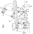
- the receiving device 40 for the electric clutch which can be clearly seen a socket 42 and a locking ring assembly 44 against which the Socket or the receiving housing 42 is sealed by O-rings 46.
- the delay spring 26 is based on the one hand on the handlebar arrangement 24 and on the other hand on the impact frame.
- the receiving device 40 further comprises a catch device 50 with a catch arm 52, an undercut 54 and a projection 56.
- the baffle frame 34 is in in the uncoupled state brought a forward position in front of the dome level 60. This guarantees that when the mating clutch opens, the receiving device 40, in which the electric clutch is arranged, not in contact with the electrical coupling of the counter-coupling comes before the mechanical coupling process is completed. Damage is avoided.
- the high run-up forces are caused by friction with a friction lever 27 which is mounted on the socket 42 and when the Socket on the impact frame rubs, damped.
- the frictional damping becomes higher, the further the frame runs forward. The frictional damping works when it compresses and spring back.
- the baffle surface 30 with the first section 32 and the second section can be clearly seen 34 and third section 36 and the receiving device 40 for the Electric clutch with attached catch device 50, comprising one Catch hook 52 as well as the undercut 54 and the projection 56.
- the mating coupling head 100 is also shown.
- the mating coupling head also includes an impact surface 30 and a catch device 50 with catch hooks 52, undercuts 54 and protrusions 56.
- 3a shows the couplings in the uncoupled state, the ones not shown Pushing devices push the baffle forward by the advance V.
- 3b shows the run-up of the clutches.
- the impact surfaces of the clutch and the counter clutch 100 touch in the middle Area 34 of the baffles 30.
- the receiving devices 40 of the electric clutch are kept at a distance D, so that the electrical coupling in the receiving device 40 do not touch and there is no damage when coupling can.
- the receiving device 40 By sliding the impact surfaces in the central area 34, the receiving device 40 height centered. The clutches do not lock because the Catch arms 52 reject the respective counter coupling.
- the closing movement of the coupling head and the electric coupling are the same and allow a high coupling and separation speed.
- baffle frame The impact on the baffle frame will possibly freeze and knocked on snow and coarse dirt.
- the storage of the baffle frames in the guide frame is advantageously designed in such a way that despite pull-push movements, rearing up, lowering and angle formation when cornering the automatic pull clutch, the electric clutch like Described here as a rigid structure and remains closed.
- the storage of the electric clutch is further designed such that a coupled Electric clutch, which is, for example, icy, can also be separated can, for example by positive locking.
- FIGS. 4a-4d are three-dimensional views of an embodiment of the Centering device according to the invention shown.
- FIG. 4a is a top view of a centering device according to the invention shown.
- the frame 20 with the connection points or suspension points can be clearly seen 21, 23.
- Openings 55 in the impact frame 30 can also be seen Movement of the baffle frame 30 causes ice, snow and dirt the openings 55 shown aborted.
- the feathers 22 are based on the frame 20 of the centering device and the handlebar arrangement 24 for the baffle.
- the three sections of the baffle 30, namely the first section 32, the second section 34 and the third section 36 can be seen.
- the first portion of the baffle 32 with the surface of the second portion the baffle 36 parallel and the second portion of the baffle 34 under one Angle arranged.
- the receiving device 40 for the electric clutch is also clearly recognizable.
- FIG. 4b shows a top view of an arrangement according to FIG. 4a.
- the impact frame 30 with the three sections 32, 34 and 36 can again be seen and the catch device 50 arranged on the impact frame, the handlebar arrangement 24 and the compression springs 22.
- FIGS. 4c and 4d show three-dimensional top views of the arrangement according to Figures 4a and 4b.
- the same reference numbers are used for the same Components related.
- the impact frame 30 can again be clearly seen in FIG. 4c and the handlebar assembly 24 with the compression spring 22, which is on the frame 20th supports the centering device.
- the delay spring 26 can be seen particularly well, which relates to the Baffle frame 30 and the handlebar assembly 24 is supported.
- the delay spring 26 essentially serves the high run-up forces when coupling onto the impact frame 30 to record, so as to damage the electrical coupling, which is in the Recording device 40 is to prevent.
- a component is thus specified for the first time with the centering device according to the invention, in that an electric clutch can be added and an automatic one Coupling and releasing the electrical connections in an automatic Pull coupling without damaging the electrical coupling.
Landscapes
- Engineering & Computer Science (AREA)
- Mechanical Engineering (AREA)
- Mechanical Operated Clutches (AREA)
- Train Traffic Observation, Control, And Security (AREA)
- Handcart (AREA)
- Electric Propulsion And Braking For Vehicles (AREA)
Abstract
- einem Führungsrahmen (20);
- einer Arretier- und Löseeinrichtung;
- einer Aufnahmeeinrichtung (40) für die Elektrokupplung.
- die Zentriervorrichtung eine Höhen- und Seitenzentriervorrichtung aufweist, so daß die in der Aufnahmeeinrichtung (40) angeordnete Elektrokupplung zweier aufeinander auflaufender Zugkupplungen (1) selbsttätig zentriert werden, ohne daß die beiden Elektrokupplungen während des Zentriervorganges miteinander in Berührung kommen.
Description
- Peter Nolle, Hans Friedrich, "Die automatische Kupplung in Europa", ETR Eisenbahntechnische Rundschau, Heft 4/92
- Adolf Felsing, Eberhardt Hoffmann "Die automatische Zugkupplung - Stand der Entwicklung und Versuchsprogramm", ETR Eisenbahntechnische Rundschau, Heft 4/95.
- Fig. 1
- eine Draufsicht auf einen erfindungsgemäßen Kupplungskopf mit einer mechanischen, einer Luftkupplung sowie der erfindungsgemäßen Elektrokupplung.
- Fig. 2
- eine Draufsicht auf die erfindungsgemäße Elektrokupplung.
- Fig. 3a - 3c
- Draufsicht auf eine erfindungsgemäße Elektrokupplung beim Kuppeln.
- Fig. 4a - 4d
- einen erfindungsgemäßen Kupplungskopf in Schnittdarstellung.
- 1:
- automatische Zugkupplung
- 3:
- mechanischer Kupplungskopf
- 5:
- Luftkupplung
- 10:
- Zentriervorrichtung
- 12:
- Elektrokupplung
- 20 :
- Führungsrahmen
- 21, 23:
- Verbindungsstellen
- 22:
- Vordrückfeder
- 24:
- Lenkeranordnung
- 26:
- Verzögerungsfeder
- 27 :
- Reibhebel
- 28:
- Prallrahmen
- 30:
- Prallfläche
- 32:
- erster Abschnitt
- 34:
- zweiter Abschnitt
- 36:
- dritter Abschnitt
- 40:
- Aufnahmeeinrichtung
- 42:
- Fassung
- 44:
- Verschlußanordnung
- 46:
- O-Ringe
- 50:
- Fangeinrichtung
- 52:
- Fangarm
- 54:
- Hinterschneidung
- 56:
- Vorsprung
- 60:
- Kupplungsebene
- 100:
- Gegenkupplungskopf
- V:
- Vorlauf
- D:
- Abstand
- α:
- Winkel zwischen den verschiedenen Prallflächen
- β:
- Winkel , unter dem die Zentriervorrichtung gegenüber der Wagenachse angeordnet ist.
Claims (16)
- Zentriervorrichtung zur Aufnahme einer Elektrokupplung einer automatischen Zugkupplung (1) mit1.1 einem Führungsrahmen (20);1.2 einer Arretier- und Löseeinrichtung;1.3 einer Aufnahmeeinrichtung (40) für die Elektrokupplung, dadurch gekennzeichnet, daß1.4 die Zentriervorrichtung eine Höhen- und Seitenzentriervorrichtung aufweist, so daß die in der Aufnahmeeinrichtung (40) angeordnete Elektrokupplung zweier aufeinander auflaufender Zugkupplungen (1) selbsttätig zentriert werden, ohne daß die beiden Elektrokupplungen während des Zentriervorganges miteinander in Berührung kommen.
- Zentriervorrichtung nach Anspruch 1, dadurch gekennzeichnet, daß die Höhen- und Seitenzentriervorrichtung eine Prallfläche (30) umfaßt mit einem ersten Abschnitt (32), einem zweiten Abschnitt (34) sowie einem dritten Abschnitt (36), wobei die Prallflächen (30) des ersten und dritten Abschnittes (32, 36) parallel versetzt zueinander verlaufen und die Prallfläche (30) des zweiten Abschnittes (34) mit der Prallfläche des ersten bzw. dritten Abschnittes (32, 36) einen Winkel von 0 < α <90° einschließt.
- Zentriervorrichtung nach Anspruch 2, dadurch gekennzeichnet, daß der Winkel α im Bereich 30 < α <60° liegt.
- Zentriervorrichtung nach Anspruch 2, dadurch gekennzeichnet, daß der Winkel α = 45° beträgt.
- Zentriervorrichtung nach einem der Ansprüche 2 bis 4, dadurch gekennzeichnet, daß die Prallfläche (30) Teil eines Prallrahmens (28) ist, der vom Führungsrahmen (20) der Zentriervorrichtung geführt wird.
- Zentriervorrichtung nach einem der Ansprüche 2 bis 5, dadurch gekennzeichnet, daß die Zentriervorrichtung eine Lenkeranordnung (24) mit einer Vordrückeinrichtung (22) umfaßt, die die Prallfläche (30) in kuppelbereiter Stellung mit Vorlauf (V) vor der Kupplungsebene (60) der Elektrokupplung hält.
- Zentriervorrichtung nach Anspruch 6, dadurch gekennzeichnet, daß der Vorlauf (V) 10 bis 20 cm beträgt.
- Zentriervorrichtung nach einem der Ansprüche 2 bis 7, dadurch gekennzeichnet, daß eine Verzögerungseinrichtung (26) vorgesehen ist, mit der hohe Auflaufkräfte abgefangen werden.
- Zentriervorrichtung gemäß Anspruch 8, dadurch gekennzeichnet, daß die Verzögerungseinrichtung eine Reibhebeleinrichtung (27) umfaßt.
- Zentriervorrichtung nach einem der Ansprüche 2 bis 9, dadurch gekennzeichnet, daß die Arretier- und Löseeinrichtung einen Vorsprung (56) sowie mindestens eine Hinterschneidung (54) umfaßt.
- Zentriervorrichtung nach einem der Ansprüche 1 bis 10, dadurch gekennzeichnet, daß die Arretier- und Löseeinrichtung einen Fanghaken (52) umfaßt.
- Automatische Zugkupplung, dadurch gekennzeichnet, daß sie eine Zentriervorrichtung gemäß einem der Ansprüche 1 bis 11 umfaßt.
- Automatische Zugkupplung gemäß Anspruch 12, dadurch gekennzeichnet, daß die Zentriervorrichtung unter einem Winkel β gegenüber der Wagenachse angeordnet ist.
- Automatische Zugkupplung gemäß Anspruch 13, dadurch gekennzeichnet, daß der Winkel β , unter dem die Zentriervorrichtung gegenüber der Wagenachse angeordnet ist, im folgenden Bereich liegt: 20° < β < 40°.
- Kuppelverfahren für die Elektrokupplung einer automatischen Zugkupplung mit einer Zentriervorrichtung gemäß einem der Ansprüche 1 bis 11, umfassend folgende Schritte:15.1 zwei Kupplungsköpfe einer automatischen Zugkupplung werden aufeinander auflaufen gelassen, wodurch15.2 der zweite Abschnitt (34) der Prallfläche (30) der Zentriervorrichtung der ersten Kupplung und der zweite Abschnitt (34) der Prallfläche (30) der Zentriervorrichtung der zweiten Kupplung miteinander zur Anlage kommen;15.3 die beiden Prallflächen (30) unter Abweisung der Gegenkupplung durch Fanghaken (52) aneinander abgleiten, so daß die von der Aufnahmeeinnichtung (40) der Zentriervorrichtung aufgenommenen Elektrokupplungen höhenzentriert werden; und daß15.4 bei weiterem Vorlaufen, wenn die Fanghaken (52) von der Gegenkupplung nicht mehr abgewiesen werden, die Fanghaken (52) sowie die Vorsprünge (56) der Arretier- und Lösevorrichtung in die Hinterschneidungen (54) der jeweiligen Gegenkupplung einrasten, wodurch die Querverschiebung und die Verhakung mit der Gegenkupplung abgeschlossen wird.
- Verfahren zum Trennen der Elektrokupplung einer automatischen Zugkupplung mit einer Zentriervorrichtung gemäß einem der Ansprüche 1 bis 11, umfassend die folgenden Schritte:16.1 die automatische Zugkupplung wird getrennt, wodurch die Vorsprünge (54) und Fanghaken (52) der Zentriervorrichtung für die Elektrokupplung aus den Hinterschneidungen (56) der jeweiligen Gegenkupplung herausgefädelt werden;16.2 der Prallrahmen wird durch die Vordrückeinnichtung (22) nach vorne gedrängt, so daß die Prallfläche (30) in kuppelbereiter Stellung mit Vorlauf vor der Kupplungsebene der Elektrokupplung gehalten wird.
Applications Claiming Priority (2)
| Application Number | Priority Date | Filing Date | Title |
|---|---|---|---|
| DE19921508 | 1999-05-10 | ||
| DE19921508A DE19921508A1 (de) | 1999-05-10 | 1999-05-10 | Zentriervorrichtung zur Aufnahme einer Elektrokupplung einer automatischen Zugkupplung |
Publications (2)
| Publication Number | Publication Date |
|---|---|
| EP1052156A1 true EP1052156A1 (de) | 2000-11-15 |
| EP1052156B1 EP1052156B1 (de) | 2003-07-30 |
Family
ID=7907587
Family Applications (1)
| Application Number | Title | Priority Date | Filing Date |
|---|---|---|---|
| EP00105995A Expired - Lifetime EP1052156B1 (de) | 1999-05-10 | 2000-03-27 | Zentriervorrichtung zur Aufnahme einer Elektrokupplung einer automatischen Zugkupplung |
Country Status (3)
| Country | Link |
|---|---|
| EP (1) | EP1052156B1 (de) |
| AT (1) | ATE246112T1 (de) |
| DE (2) | DE19921508A1 (de) |
Citations (3)
| Publication number | Priority date | Publication date | Assignee | Title |
|---|---|---|---|---|
| GB1255216A (en) * | 1969-03-05 | 1971-12-01 | Mini Verkehrswesen | Improvements in railway vehicle automatic central buffer couplings |
| US4232793A (en) * | 1979-04-18 | 1980-11-11 | Pullman Incorporated | Car coupling arrangement for railway passenger cars |
| EP0808760A1 (de) * | 1996-05-24 | 1997-11-26 | SCHARFENBERGKUPPLUNG GmbH & Co. KG | Kabelkupplung für Schienenfahrzeuge |
Family Cites Families (2)
| Publication number | Priority date | Publication date | Assignee | Title |
|---|---|---|---|---|
| DE1438777B2 (de) * | 1964-02-24 | 1971-09-23 | Selbsttaetige elektrische kupplungsvorrichtung | |
| DE1904513A1 (de) * | 1968-12-06 | 1970-08-20 | Mini Verkehrswesen | Selbstverriegelnde Rohrleitungskupplung fuer Schienenfahrzeuge |
-
1999
- 1999-05-10 DE DE19921508A patent/DE19921508A1/de not_active Withdrawn
-
2000
- 2000-03-27 EP EP00105995A patent/EP1052156B1/de not_active Expired - Lifetime
- 2000-03-27 AT AT00105995T patent/ATE246112T1/de not_active IP Right Cessation
- 2000-03-27 DE DE50003065T patent/DE50003065D1/de not_active Expired - Lifetime
Patent Citations (3)
| Publication number | Priority date | Publication date | Assignee | Title |
|---|---|---|---|---|
| GB1255216A (en) * | 1969-03-05 | 1971-12-01 | Mini Verkehrswesen | Improvements in railway vehicle automatic central buffer couplings |
| US4232793A (en) * | 1979-04-18 | 1980-11-11 | Pullman Incorporated | Car coupling arrangement for railway passenger cars |
| EP0808760A1 (de) * | 1996-05-24 | 1997-11-26 | SCHARFENBERGKUPPLUNG GmbH & Co. KG | Kabelkupplung für Schienenfahrzeuge |
Also Published As
| Publication number | Publication date |
|---|---|
| DE19921508A1 (de) | 2000-11-23 |
| ATE246112T1 (de) | 2003-08-15 |
| DE50003065D1 (de) | 2003-09-04 |
| EP1052156B1 (de) | 2003-07-30 |
Similar Documents
| Publication | Publication Date | Title |
|---|---|---|
| EP2013040B1 (de) | Kupplungssystem zum verbinden von versorgungsleitungen | |
| EP3915838B1 (de) | Fahrerassistenzsystem und verfahren zum ankuppeln eines anhängers an ein zugfahrzeug | |
| DE102022104693A1 (de) | Automatische zugkupplung sowie verfahren zum betreiben einer automatischen zugkupplung | |
| EP1597098B1 (de) | Kupplungsvorrichtung für zugfahrzeuge | |
| EP0342502A1 (de) | Selbsttätige Kupplung für Schienenfahrzeuge | |
| WO2021028150A1 (de) | Elektrozugkupplung und zugkupplung mit einer solchen elektrozugkupplung | |
| DE3601951C1 (de) | Klauenkupplung fuer Spiel- und Modellbahnen | |
| EP1052156B1 (de) | Zentriervorrichtung zur Aufnahme einer Elektrokupplung einer automatischen Zugkupplung | |
| WO2017009441A1 (de) | Ankoppelungseinheit | |
| EP1052157B1 (de) | Elektrokupplung für eine automatische Zugkupplung | |
| DE102017122552A1 (de) | Übergangskupplung zum Kuppeln von zwei Fahrzeugen mit zueinander verschiedenen Kupplungen und Übergangskupplungssystem | |
| DE3534325A1 (de) | Vorentkuppelbare anhaengerkupplungsanordnung fuer schienenfahrzeuge, insbesondere bei modelleisenbahnen | |
| EP0618126A2 (de) | Automatische Kupplung für Schienenfahrzeuge | |
| DE1039432B (de) | Kupplung fuer Modelleisenbahnfahrzeuge | |
| DE102024137616A1 (de) | Automatische Zugkupplung und Kupplungsanordnung | |
| EP1806267A2 (de) | Kupplungskopf einer automatischen Mittelpufferkupplung für Schienenfahrzeuge nach Art einer Willison-Kupplung mit der Willison-Kontur | |
| DE4041451C2 (de) | Selbsttätige Zugkupplung für Schienenfahrzeuge | |
| DE19544606A1 (de) | Automatische Mittelpufferkupplung für Schienenfahrzeuge | |
| CH383434A (de) | Selbsttätige Kupplung an Fahrzeugen, insbesondere für den Schienenverkehr | |
| DE19713913A1 (de) | Eisenbahn-Kupplung mit ESL-Modul | |
| EP2390156A1 (de) | Kupplungskopf für ein spurgeführtes Fahrzeug | |
| DE1808174A1 (de) | Leitungskupplung zu automatischen Mittelpufferkupplungen von Schienenfahrzeugen | |
| DE3823247A1 (de) | Selbsttaetig kuppelnde zugkupplung fuer schienenfahrzeuge | |
| DD283356A5 (de) | Uebergangskupplung fuer schienenfahrzeuge | |
| AT17007U1 (de) |
Legal Events
| Date | Code | Title | Description |
|---|---|---|---|
| PUAI | Public reference made under article 153(3) epc to a published international application that has entered the european phase |
Free format text: ORIGINAL CODE: 0009012 |
|
| AK | Designated contracting states |
Kind code of ref document: A1 Designated state(s): AT BE CH CY DE DK ES FI FR GB GR IE IT LI LU MC NL PT SE |
|
| AX | Request for extension of the european patent |
Free format text: AL;LT;LV;MK;RO;SI |
|
| 17P | Request for examination filed |
Effective date: 20010515 |
|
| AKX | Designation fees paid |
Free format text: AT BE CH CY DE DK ES FI FR GB GR IE IT LI LU MC NL PT SE |
|
| 17Q | First examination report despatched |
Effective date: 20010711 |
|
| GRAH | Despatch of communication of intention to grant a patent |
Free format text: ORIGINAL CODE: EPIDOS IGRA |
|
| GRAH | Despatch of communication of intention to grant a patent |
Free format text: ORIGINAL CODE: EPIDOS IGRA |
|
| GRAA | (expected) grant |
Free format text: ORIGINAL CODE: 0009210 |
|
| AK | Designated contracting states |
Designated state(s): AT BE CH CY DE DK ES FI FR GB GR IE IT LI LU MC NL PT SE |
|
| PG25 | Lapsed in a contracting state [announced via postgrant information from national office to epo] |
Ref country code: CY Free format text: LAPSE BECAUSE OF FAILURE TO SUBMIT A TRANSLATION OF THE DESCRIPTION OR TO PAY THE FEE WITHIN THE PRESCRIBED TIME-LIMIT Effective date: 20030730 Ref country code: IE Free format text: LAPSE BECAUSE OF FAILURE TO SUBMIT A TRANSLATION OF THE DESCRIPTION OR TO PAY THE FEE WITHIN THE PRESCRIBED TIME-LIMIT Effective date: 20030730 Ref country code: GB Free format text: LAPSE BECAUSE OF FAILURE TO SUBMIT A TRANSLATION OF THE DESCRIPTION OR TO PAY THE FEE WITHIN THE PRESCRIBED TIME-LIMIT Effective date: 20030730 Ref country code: FI Free format text: LAPSE BECAUSE OF FAILURE TO SUBMIT A TRANSLATION OF THE DESCRIPTION OR TO PAY THE FEE WITHIN THE PRESCRIBED TIME-LIMIT Effective date: 20030730 |
|
| REG | Reference to a national code |
Ref country code: GB Ref legal event code: FG4D Free format text: NOT ENGLISH |
|
| REG | Reference to a national code |
Ref country code: CH Ref legal event code: EP |
|
| REG | Reference to a national code |
Ref country code: IE Ref legal event code: FG4D Free format text: GERMAN |
|
| REF | Corresponds to: |
Ref document number: 50003065 Country of ref document: DE Date of ref document: 20030904 Kind code of ref document: P |
|
| PG25 | Lapsed in a contracting state [announced via postgrant information from national office to epo] |
Ref country code: DK Free format text: LAPSE BECAUSE OF FAILURE TO SUBMIT A TRANSLATION OF THE DESCRIPTION OR TO PAY THE FEE WITHIN THE PRESCRIBED TIME-LIMIT Effective date: 20031030 Ref country code: GR Free format text: LAPSE BECAUSE OF FAILURE TO SUBMIT A TRANSLATION OF THE DESCRIPTION OR TO PAY THE FEE WITHIN THE PRESCRIBED TIME-LIMIT Effective date: 20031030 Ref country code: SE Free format text: LAPSE BECAUSE OF FAILURE TO SUBMIT A TRANSLATION OF THE DESCRIPTION OR TO PAY THE FEE WITHIN THE PRESCRIBED TIME-LIMIT Effective date: 20031030 |
|
| PG25 | Lapsed in a contracting state [announced via postgrant information from national office to epo] |
Ref country code: ES Free format text: LAPSE BECAUSE OF FAILURE TO SUBMIT A TRANSLATION OF THE DESCRIPTION OR TO PAY THE FEE WITHIN THE PRESCRIBED TIME-LIMIT Effective date: 20031110 |
|
| PG25 | Lapsed in a contracting state [announced via postgrant information from national office to epo] |
Ref country code: PT Free format text: LAPSE BECAUSE OF FAILURE TO SUBMIT A TRANSLATION OF THE DESCRIPTION OR TO PAY THE FEE WITHIN THE PRESCRIBED TIME-LIMIT Effective date: 20031230 |
|
| GBV | Gb: ep patent (uk) treated as always having been void in accordance with gb section 77(7)/1977 [no translation filed] |
Effective date: 20030730 |
|
| REG | Reference to a national code |
Ref country code: IE Ref legal event code: FD4D |
|
| PG25 | Lapsed in a contracting state [announced via postgrant information from national office to epo] |
Ref country code: MC Free format text: LAPSE BECAUSE OF NON-PAYMENT OF DUE FEES Effective date: 20040331 Ref country code: LI Free format text: LAPSE BECAUSE OF NON-PAYMENT OF DUE FEES Effective date: 20040331 Ref country code: CH Free format text: LAPSE BECAUSE OF NON-PAYMENT OF DUE FEES Effective date: 20040331 |
|
| ET | Fr: translation filed | ||
| PLBE | No opposition filed within time limit |
Free format text: ORIGINAL CODE: 0009261 |
|
| STAA | Information on the status of an ep patent application or granted ep patent |
Free format text: STATUS: NO OPPOSITION FILED WITHIN TIME LIMIT |
|
| 26N | No opposition filed |
Effective date: 20040504 |
|
| REG | Reference to a national code |
Ref country code: CH Ref legal event code: PL |
|
| PGFP | Annual fee paid to national office [announced via postgrant information from national office to epo] |
Ref country code: NL Payment date: 20050317 Year of fee payment: 6 |
|
| PGFP | Annual fee paid to national office [announced via postgrant information from national office to epo] |
Ref country code: FR Payment date: 20050318 Year of fee payment: 6 |
|
| PGFP | Annual fee paid to national office [announced via postgrant information from national office to epo] |
Ref country code: AT Payment date: 20050322 Year of fee payment: 6 Ref country code: BE Payment date: 20050322 Year of fee payment: 6 |
|
| PGFP | Annual fee paid to national office [announced via postgrant information from national office to epo] |
Ref country code: LU Payment date: 20050325 Year of fee payment: 6 |
|
| PG25 | Lapsed in a contracting state [announced via postgrant information from national office to epo] |
Ref country code: AT Free format text: LAPSE BECAUSE OF NON-PAYMENT OF DUE FEES Effective date: 20060327 |
|
| PG25 | Lapsed in a contracting state [announced via postgrant information from national office to epo] |
Ref country code: LU Free format text: LAPSE BECAUSE OF NON-PAYMENT OF DUE FEES Effective date: 20060331 Ref country code: BE Free format text: LAPSE BECAUSE OF NON-PAYMENT OF DUE FEES Effective date: 20060331 |
|
| PGFP | Annual fee paid to national office [announced via postgrant information from national office to epo] |
Ref country code: IT Payment date: 20060331 Year of fee payment: 7 |
|
| PG25 | Lapsed in a contracting state [announced via postgrant information from national office to epo] |
Ref country code: NL Free format text: LAPSE BECAUSE OF NON-PAYMENT OF DUE FEES Effective date: 20061001 |
|
| NLV4 | Nl: lapsed or anulled due to non-payment of the annual fee |
Effective date: 20061001 |
|
| REG | Reference to a national code |
Ref country code: FR Ref legal event code: ST Effective date: 20061130 |
|
| BERE | Be: lapsed |
Owner name: *KNORR-BREMSE SYSTEME FUR SCHIENENFAHRZEUGE G.M.B. Effective date: 20060331 |
|
| PG25 | Lapsed in a contracting state [announced via postgrant information from national office to epo] |
Ref country code: FR Free format text: LAPSE BECAUSE OF NON-PAYMENT OF DUE FEES Effective date: 20060331 |
|
| PG25 | Lapsed in a contracting state [announced via postgrant information from national office to epo] |
Ref country code: IT Free format text: LAPSE BECAUSE OF NON-PAYMENT OF DUE FEES Effective date: 20070327 |
|
| PGFP | Annual fee paid to national office [announced via postgrant information from national office to epo] |
Ref country code: DE Payment date: 20190325 Year of fee payment: 20 |
|
| REG | Reference to a national code |
Ref country code: DE Ref legal event code: R071 Ref document number: 50003065 Country of ref document: DE |