EP1051781B1 - Laser delivery system with diffractive optic beam integration - Google Patents
Laser delivery system with diffractive optic beam integration Download PDFInfo
- Publication number
- EP1051781B1 EP1051781B1 EP99905449A EP99905449A EP1051781B1 EP 1051781 B1 EP1051781 B1 EP 1051781B1 EP 99905449 A EP99905449 A EP 99905449A EP 99905449 A EP99905449 A EP 99905449A EP 1051781 B1 EP1051781 B1 EP 1051781B1
- Authority
- EP
- European Patent Office
- Prior art keywords
- excimer laser
- laser system
- diffractive
- diffractive optic
- uniform
- Prior art date
- Legal status (The legal status is an assumption and is not a legal conclusion. Google has not performed a legal analysis and makes no representation as to the accuracy of the status listed.)
- Expired - Lifetime
Links
- 230000010354 integration Effects 0.000 title claims abstract description 25
- 238000009826 distribution Methods 0.000 claims abstract description 30
- 230000001131 transforming effect Effects 0.000 claims abstract description 5
- 238000011282 treatment Methods 0.000 claims description 24
- 238000002679 ablation Methods 0.000 claims description 20
- 210000004087 cornea Anatomy 0.000 claims description 20
- VYPSYNLAJGMNEJ-UHFFFAOYSA-N silicon dioxide Inorganic materials O=[Si]=O VYPSYNLAJGMNEJ-UHFFFAOYSA-N 0.000 claims description 6
- PQXKHYXIUOZZFA-UHFFFAOYSA-M lithium fluoride Chemical compound [Li+].[F-] PQXKHYXIUOZZFA-UHFFFAOYSA-M 0.000 claims description 4
- 230000000694 effects Effects 0.000 claims description 3
- WUKWITHWXAAZEY-UHFFFAOYSA-L calcium difluoride Chemical compound [F-].[F-].[Ca+2] WUKWITHWXAAZEY-UHFFFAOYSA-L 0.000 claims description 2
- 229910001634 calcium fluoride Inorganic materials 0.000 claims description 2
- 239000005350 fused silica glass Substances 0.000 claims description 2
- ORUIBWPALBXDOA-UHFFFAOYSA-L magnesium fluoride Chemical compound [F-].[F-].[Mg+2] ORUIBWPALBXDOA-UHFFFAOYSA-L 0.000 claims description 2
- 229910001635 magnesium fluoride Inorganic materials 0.000 claims description 2
- 239000010453 quartz Substances 0.000 claims description 2
- 229910052594 sapphire Inorganic materials 0.000 claims description 2
- 239000010980 sapphire Substances 0.000 claims description 2
- 239000012780 transparent material Substances 0.000 claims 1
- 238000000034 method Methods 0.000 abstract description 25
- 238000003384 imaging method Methods 0.000 abstract description 7
- 210000001519 tissue Anatomy 0.000 description 15
- 230000003287 optical effect Effects 0.000 description 14
- 230000002123 temporal effect Effects 0.000 description 13
- 238000002430 laser surgery Methods 0.000 description 12
- 238000001356 surgical procedure Methods 0.000 description 10
- 201000009310 astigmatism Diseases 0.000 description 6
- 230000008859 change Effects 0.000 description 4
- 210000000981 epithelium Anatomy 0.000 description 3
- 238000013532 laser treatment Methods 0.000 description 3
- 208000001491 myopia Diseases 0.000 description 3
- 230000004379 myopia Effects 0.000 description 3
- 208000014733 refractive error Diseases 0.000 description 3
- 206010020675 Hypermetropia Diseases 0.000 description 2
- 230000004075 alteration Effects 0.000 description 2
- ISQINHMJILFLAQ-UHFFFAOYSA-N argon hydrofluoride Chemical compound F.[Ar] ISQINHMJILFLAQ-UHFFFAOYSA-N 0.000 description 2
- 230000005540 biological transmission Effects 0.000 description 2
- 230000003247 decreasing effect Effects 0.000 description 2
- 238000010586 diagram Methods 0.000 description 2
- 238000005516 engineering process Methods 0.000 description 2
- 201000006318 hyperopia Diseases 0.000 description 2
- 230000004305 hyperopia Effects 0.000 description 2
- 0 CC(C)C1(*)C=C(*)*=C1 Chemical compound CC(C)C1(*)C=C(*)*=C1 0.000 description 1
- 230000002159 abnormal effect Effects 0.000 description 1
- 230000002745 absorbent Effects 0.000 description 1
- 239000002250 absorbent Substances 0.000 description 1
- 230000002411 adverse Effects 0.000 description 1
- 238000004458 analytical method Methods 0.000 description 1
- 239000006117 anti-reflective coating Substances 0.000 description 1
- 239000004020 conductor Substances 0.000 description 1
- 238000010276 construction Methods 0.000 description 1
- 238000001312 dry etching Methods 0.000 description 1
- 238000005530 etching Methods 0.000 description 1
- 239000005357 flat glass Substances 0.000 description 1
- 239000012634 fragment Substances 0.000 description 1
- 239000007789 gas Substances 0.000 description 1
- 239000011521 glass Substances 0.000 description 1
- 238000010438 heat treatment Methods 0.000 description 1
- 238000000608 laser ablation Methods 0.000 description 1
- 230000014759 maintenance of location Effects 0.000 description 1
- 238000004519 manufacturing process Methods 0.000 description 1
- 239000000463 material Substances 0.000 description 1
- 230000007246 mechanism Effects 0.000 description 1
- 238000012986 modification Methods 0.000 description 1
- 230000004048 modification Effects 0.000 description 1
- 230000000737 periodic effect Effects 0.000 description 1
- 230000002093 peripheral effect Effects 0.000 description 1
- 238000006303 photolysis reaction Methods 0.000 description 1
- 230000003252 repetitive effect Effects 0.000 description 1
- 238000000926 separation method Methods 0.000 description 1
- 239000000377 silicon dioxide Substances 0.000 description 1
- 239000000758 substrate Substances 0.000 description 1
- 230000001225 therapeutic effect Effects 0.000 description 1
- 230000003685 thermal hair damage Effects 0.000 description 1
- 230000009466 transformation Effects 0.000 description 1
Images


Classifications
-
- G—PHYSICS
- G02—OPTICS
- G02B—OPTICAL ELEMENTS, SYSTEMS OR APPARATUS
- G02B27/00—Optical systems or apparatus not provided for by any of the groups G02B1/00 - G02B26/00, G02B30/00
- G02B27/09—Beam shaping, e.g. changing the cross-sectional area, not otherwise provided for
- G02B27/0927—Systems for changing the beam intensity distribution, e.g. Gaussian to top-hat
-
- A—HUMAN NECESSITIES
- A61—MEDICAL OR VETERINARY SCIENCE; HYGIENE
- A61F—FILTERS IMPLANTABLE INTO BLOOD VESSELS; PROSTHESES; DEVICES PROVIDING PATENCY TO, OR PREVENTING COLLAPSING OF, TUBULAR STRUCTURES OF THE BODY, e.g. STENTS; ORTHOPAEDIC, NURSING OR CONTRACEPTIVE DEVICES; FOMENTATION; TREATMENT OR PROTECTION OF EYES OR EARS; BANDAGES, DRESSINGS OR ABSORBENT PADS; FIRST-AID KITS
- A61F9/00—Methods or devices for treatment of the eyes; Devices for putting in contact-lenses; Devices to correct squinting; Apparatus to guide the blind; Protective devices for the eyes, carried on the body or in the hand
- A61F9/007—Methods or devices for eye surgery
- A61F9/008—Methods or devices for eye surgery using laser
- A61F9/00802—Methods or devices for eye surgery using laser for photoablation
- A61F9/00804—Refractive treatments
-
- A—HUMAN NECESSITIES
- A61—MEDICAL OR VETERINARY SCIENCE; HYGIENE
- A61F—FILTERS IMPLANTABLE INTO BLOOD VESSELS; PROSTHESES; DEVICES PROVIDING PATENCY TO, OR PREVENTING COLLAPSING OF, TUBULAR STRUCTURES OF THE BODY, e.g. STENTS; ORTHOPAEDIC, NURSING OR CONTRACEPTIVE DEVICES; FOMENTATION; TREATMENT OR PROTECTION OF EYES OR EARS; BANDAGES, DRESSINGS OR ABSORBENT PADS; FIRST-AID KITS
- A61F9/00—Methods or devices for treatment of the eyes; Devices for putting in contact-lenses; Devices to correct squinting; Apparatus to guide the blind; Protective devices for the eyes, carried on the body or in the hand
- A61F9/007—Methods or devices for eye surgery
- A61F9/008—Methods or devices for eye surgery using laser
- A61F9/00802—Methods or devices for eye surgery using laser for photoablation
- A61F9/00817—Beam shaping with masks
-
- B—PERFORMING OPERATIONS; TRANSPORTING
- B23—MACHINE TOOLS; METAL-WORKING NOT OTHERWISE PROVIDED FOR
- B23K—SOLDERING OR UNSOLDERING; WELDING; CLADDING OR PLATING BY SOLDERING OR WELDING; CUTTING BY APPLYING HEAT LOCALLY, e.g. FLAME CUTTING; WORKING BY LASER BEAM
- B23K26/00—Working by laser beam, e.g. welding, cutting or boring
- B23K26/02—Positioning or observing the workpiece, e.g. with respect to the point of impact; Aligning, aiming or focusing the laser beam
- B23K26/06—Shaping the laser beam, e.g. by masks or multi-focusing
- B23K26/064—Shaping the laser beam, e.g. by masks or multi-focusing by means of optical elements, e.g. lenses, mirrors or prisms
- B23K26/066—Shaping the laser beam, e.g. by masks or multi-focusing by means of optical elements, e.g. lenses, mirrors or prisms by using masks
-
- G—PHYSICS
- G02—OPTICS
- G02B—OPTICAL ELEMENTS, SYSTEMS OR APPARATUS
- G02B27/00—Optical systems or apparatus not provided for by any of the groups G02B1/00 - G02B26/00, G02B30/00
- G02B27/09—Beam shaping, e.g. changing the cross-sectional area, not otherwise provided for
-
- G—PHYSICS
- G02—OPTICS
- G02B—OPTICAL ELEMENTS, SYSTEMS OR APPARATUS
- G02B27/00—Optical systems or apparatus not provided for by any of the groups G02B1/00 - G02B26/00, G02B30/00
- G02B27/09—Beam shaping, e.g. changing the cross-sectional area, not otherwise provided for
- G02B27/0938—Using specific optical elements
- G02B27/0944—Diffractive optical elements, e.g. gratings, holograms
-
- H—ELECTRICITY
- H01—ELECTRIC ELEMENTS
- H01S—DEVICES USING THE PROCESS OF LIGHT AMPLIFICATION BY STIMULATED EMISSION OF RADIATION [LASER] TO AMPLIFY OR GENERATE LIGHT; DEVICES USING STIMULATED EMISSION OF ELECTROMAGNETIC RADIATION IN WAVE RANGES OTHER THAN OPTICAL
- H01S3/00—Lasers, i.e. devices using stimulated emission of electromagnetic radiation in the infrared, visible or ultraviolet wave range
- H01S3/005—Optical devices external to the laser cavity, specially adapted for lasers, e.g. for homogenisation of the beam or for manipulating laser pulses, e.g. pulse shaping
-
- A—HUMAN NECESSITIES
- A61—MEDICAL OR VETERINARY SCIENCE; HYGIENE
- A61B—DIAGNOSIS; SURGERY; IDENTIFICATION
- A61B18/00—Surgical instruments, devices or methods for transferring non-mechanical forms of energy to or from the body
- A61B18/18—Surgical instruments, devices or methods for transferring non-mechanical forms of energy to or from the body by applying electromagnetic radiation, e.g. microwaves
- A61B18/20—Surgical instruments, devices or methods for transferring non-mechanical forms of energy to or from the body by applying electromagnetic radiation, e.g. microwaves using laser
- A61B18/201—Surgical instruments, devices or methods for transferring non-mechanical forms of energy to or from the body by applying electromagnetic radiation, e.g. microwaves using laser with beam delivery through a hollow tube, e.g. forming an articulated arm ; Hand-pieces therefor
-
- A—HUMAN NECESSITIES
- A61—MEDICAL OR VETERINARY SCIENCE; HYGIENE
- A61F—FILTERS IMPLANTABLE INTO BLOOD VESSELS; PROSTHESES; DEVICES PROVIDING PATENCY TO, OR PREVENTING COLLAPSING OF, TUBULAR STRUCTURES OF THE BODY, e.g. STENTS; ORTHOPAEDIC, NURSING OR CONTRACEPTIVE DEVICES; FOMENTATION; TREATMENT OR PROTECTION OF EYES OR EARS; BANDAGES, DRESSINGS OR ABSORBENT PADS; FIRST-AID KITS
- A61F9/00—Methods or devices for treatment of the eyes; Devices for putting in contact-lenses; Devices to correct squinting; Apparatus to guide the blind; Protective devices for the eyes, carried on the body or in the hand
- A61F9/007—Methods or devices for eye surgery
- A61F9/008—Methods or devices for eye surgery using laser
- A61F2009/00844—Feedback systems
-
- A—HUMAN NECESSITIES
- A61—MEDICAL OR VETERINARY SCIENCE; HYGIENE
- A61F—FILTERS IMPLANTABLE INTO BLOOD VESSELS; PROSTHESES; DEVICES PROVIDING PATENCY TO, OR PREVENTING COLLAPSING OF, TUBULAR STRUCTURES OF THE BODY, e.g. STENTS; ORTHOPAEDIC, NURSING OR CONTRACEPTIVE DEVICES; FOMENTATION; TREATMENT OR PROTECTION OF EYES OR EARS; BANDAGES, DRESSINGS OR ABSORBENT PADS; FIRST-AID KITS
- A61F9/00—Methods or devices for treatment of the eyes; Devices for putting in contact-lenses; Devices to correct squinting; Apparatus to guide the blind; Protective devices for the eyes, carried on the body or in the hand
- A61F9/007—Methods or devices for eye surgery
- A61F9/008—Methods or devices for eye surgery using laser
- A61F2009/00861—Methods or devices for eye surgery using laser adapted for treatment at a particular location
- A61F2009/00872—Cornea
Definitions
- This invention relates generally to light beam systems for modifying the spatial intensity distribution of a beam, and more particularly to a light beam system for modifying the spatial intensity distribution of an excimer laser beam to produce a beam of substantially uniform intensity for tissue ablation.
- Excimer lasers have been used for various applications, including tissue ablation such as corneal ablation and other surgical procedures.
- the cross-section of the intensity profile of a typical excimer laser beam is typically not spatially uniform.
- the beam has a generally rectangular cross-section.
- the intensity along the long axis of the rectangular beam is substantially constant over the central portion of the beam.
- the intensity along the short axis of the beam is substantially gaussian. Therefore, the divergence of the excimer laser beam is different along the two axes. As a result, the beam changes shape as it is emitted and travels away from the excimer laser.
- Producing a laser beam with a substantially uniform intensity is important in many surgical procedures such as tissue ablation, particularly in corneal ablation for refractive correction or therapeutic purposes.
- the laser beam should maintain the shape required by the ablation algorithm throughout the ablation procedure.
- Another method of improving beam intensity employs complex optical systems such as a set of mirrors, prisms, or lenses to break the beam into a series of beamlets.
- the beamlets are overlapped in a manner to produce a uniform intensity through an aperture of a mask.
- the aperture is imaged onto the corneal plane.
- Still another method employs a rotatable mask formed with one or more apertures having a geometric spiral shape to modify the spatial intensity distribution of a beam, as disclosed in U.S. Patent No. 5,651,784 issued to Klopotek for "ROTATABLE APERTURE APPARATUS AND METHODS FOR SELECTIVE PHOTOABLATION OF SURFACE".
- Temporal beam integrators such as a rotating dove prism or k-mirror have been used to modify the laser beam to improve the average uniformity of several laser pulses over a time interval.
- U.S. Patent No. 5,646,791 to Glockler for "METHOD AND APPARATUS FOR TEMPORAL AND SPATIAL BEAM INTEGRATION” employs a spatial beam integrator for improving the spatial uniformity of a laser beam intensity profile and a separate rotating temporal beam integrator for maintaining the uniformity of the laser beam intensity over the laser pulse time interval.
- the spatial beam integrator includes a plurality of prisms distributed about a hollow center. The outlet face of each prism is precisely angled with respect to the body axis of the spatial beam integrator to refract the beam towards the center.
- the spatial beam integrator may be stationary or rotated to generate a stationary or rotated beam with respect to the spatial beam integrator.
- the temporal beam integrator includes a pair of rotating cylindrical lenses spaced along the beam axis by a distance substantially equal to the sum of the focal lengths of both lenses.
- U.S. Patent 5,610,733 to Feldman for "BEAM-HOMOGENIZER,” and U.S. Patent 4,547,037 to Case for "HOLOGRAPHIC METHOD FOR PRODUCING DESIRED WAVEFRONT TRANSFORMATION,” employ diffractive optics for changing the energy distribution of laser beams.
- a diffractive optical element is placed in the laser beam path at a first plane.
- a desired output energy is generated at a second plane.
- DE-C-19619481 upon which the two part form of claim 1 is based, discloses the use of multiple cylindrical lens components to improve the uniformity of an excimer laser beam, and US-A-5 376 086 shows the use of diffractive elements to control laser power transmission, but not uniformity.
- the prior methods of ablating tissue employ complicated and expensive apparatus to improve uniformity of the laser beam.
- the present invention is set forth in claim 1, and an embodiment which is described hereinafter in detail comprises an excimer laser system for tissue ablation in which an argon fluoride excimer laser generates a rectangular nonuniform beam of pulsed laser energy along a path.
- the nonuniform beam has a nonuniform spatial intensity distribution.
- a diffractive optic diffuser is spaced from the laser and includes a transparent etched pattern disposed along the path of the beam for transforming the nonuniform beam into a spatially integrated circular beam having a substantially uniform spatial intensity distribution.
- a positive lens is placed downstream of the diffractive optic diffuser for focusing the spatially integrated beam to a desired spatial intensity distribution at a spatial integration plane.
- This invention employs a diffractive grating technique to modify the spatial intensity distribution of an excimer laser beam.
- Conventional diffractive gratings include a repetitive array of diffracting elements, with apertures or obstacles, that have the effect of producing periodic alterations in the phase, amplitude, or both of an emergent wave such as a laser beam.
- One simple arrangement is an obstacle with a series of slits evenly spaced from each other.
- a more common diffractive grating device is a clear glass plate with ordered or random parallel notches scratched or ruled into the surface of the flat glass plate. The notches each serve as a source of scattered light and combine to form a regular array of parallel line sources.
- the diffractive grating device When the grating is totally transparent with negligible amplitude modulation, the regular variations in the optical thickness across the grating yield a modulation in phase. In that case, the diffractive grating device performs as transmission phase grating.
- a diffractive grating pattern etched in a transparent medium transforms an excimer laser beam into an output beam with a substantially uniform spatial intensity distribution.
- a generally rectangular excimer laser beam 10 is projected along the beam axis 11 toward a diffractive element 12.
- the intensity along the long axis (x-axis) of the beam 10 is generally uniform, while the intensity along the short axis (y-axis) is substantially gaussian.
- the diffractive element 12 has a generally planar body 16 that includes a transparent portion 18 which receives and diffractively transforms the laser beam 10.
- the diffracted beam 20 emerging from the diffractive element 12 travels along the beam axis 11 through a positive or converging lens 22 which converges the diffracted beam 20.
- the converged beam 30 travels along the beam axis 11 and has a transformed pattern at a spatial integration plane 32.
- the transparent portion 18 has a generally rectangular shape sized for receiving the entire rectangular beam 10.
- the transparent portion 18 of the diffractive element 12 has a diffractive pattern etched in a transparent medium.
- the transparent medium may be a glass-like silica material.
- the transparent medium desirably is substantially non-absorbent and non-reflective to the excimer laser beam 10.
- the transparent medium may include fused silica, quartz, magnesium fluoride, calcium fluoride, lithium fluoride, or sapphire.
- the diffractive pattern on the transparent medium forms a diffractive grating that is configured to transform the nonuniform excimer laser beam 10 to a spatially integrated excimer beam 20 with a spatial intensity distribution that is substantially uniform across the cross-section of the beam.
- the cross-sectional shape of the converged beam 30 is circular.
- the spatial intensity distribution advantageously has a top-hat shape with a circular central region that is substantially uniform and covers a large portion of the cross-section of the converged beam 30 (see the illustrated spatial intensity distribution at the spatial integration plane 32 of Figure 1).
- Other spatial intensity distributions are possible using different diffractive gratings.
- the configuration of the diffractive pattern depends largely on the shape and spatial intensity distribution of the desired converged beam 30, and also on the characteristics of the incoming beam 10 such as its wavelength and spatial intensity distribution.
- the diffractive pattern may include a plurality of properly spaced etched regions such as lines, spots, or the like. For excimer lasers with short wavelengths in the neighborhood of about 193 nanometers (nm), the spacings of the etched regions in the diffractive pattern are advantageously small and precise.
- Known etching techniques such as dry etching may be used to etch the diffractive pattern on the transparent portion 18.
- the converging lens 22 converges or focuses the diffracted beam 20 as the converged beam 30 to the spatial integration plane 32.
- the cross-section of the converged beam 30 at the spatial integration plane 32 is substantially circular and has a spatial intensity distribution with a top-hat profile.
- the uniform central region 36 of the intensity distribution desirably covers at least about 70%, more desirably close to 85%, of the cross-section of the beam 30.
- the size of the cross-section of the beam 30 at the spatial integration plane 32 is advantageously sized to correspond to the largest area ablated with a single laser pulse. For instance, a dimension across the cross-section of the beam 30 at the spatial integration plane 32 may typically range from 3 to 12 mm.
- Figures 1 and 2 show a planar convex lens 22, but other types of converging lenses 22 may be selected based on focal length to minimize aberration.
- An anti-reflective coating may be applied to prevent or minimize reflection of the beam 20 from the positive lens 22.
- the laser beam 10 is directed along the beam axis 11 through the transparent portion 18 of the diffractive element 12 which is aligned with the laser beam 10 to receive the entire laser beam 10.
- the etched diffractive pattern of the transparent portion 18 serves as a diffractive control angle diffuser for altering the spatial intensity distribution of the laser beam 10.
- the transparent portion 18 transforms the generally rectangular gaussian laser beam 10 to the generally circular beam 20 with a substantially uniform intensity distribution.
- the positive lens 22 is aligned with the beam axis 11 and converges the spatially integrated beam 20 to a desired size.
- the cross-section of the converged beam 30 at the spatial integration plane 32 is substantially circular and uniform in spatial intensity, which is desirable for surgical procedures such as corneal ablation.
- the diffractive element 12 and converging lens 22 spatially integrate the rectangular beam 10 to form the beam 30 having a substantially uniform intensity profile at the spatial integration plane.
- the cross-section of the beam 30 is circular, or may have other shapes.
- the beam 30 desirably has the uniform intensity central region 36 that covers at least about 85% of the area of the cross-section of the beam 30.
- the uniform intensity central region 36 includes a significant portion of the total energy of the rectangular beam 10 because there is no significant loss of energy through the diffractive optic apparatus. This renders the apparatus highly efficient.
- a binary diffractive optic 12 positioned approximately 15 mm from the converging lens 22 of 250 mm focal length produced a uniform circular beam of approximately 12 mm at the spatial integration plane 32.
- the binary optic employed was designed by Digital Optics Corporation of Charlotte, North Carolina. Other companies skilled in the art of diffractive optic design can produce similar gratings.
- the size of the spatially integrated beam at the spatial integration plane may be varied by varying the focal length of the lens 22.
- diffractive element 12 may be employed which do not require the use of a separate lens 22.
- Converging lens 22 may be ground on one surface of diffractive element 12, such as shown in Figure 8.
- diffractive element 12 may be rotated between pulses to provide temporal integration of the beam.
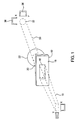
- Figure 3 illustrates the application of the invention to an ophthalmological laser surgery optical system 100 and the relative orientation of the components in the system 100.
- the particular components and configurations described below are merely for illustrative purposes.
- the diffractive optic apparatus can be used with a variety of different excimer laser systems.
- a beam 102 is generated from a suitable laser source 104, such as an argon fluoride (ArF) excimer laser beam source for generating a laser beam in the far ultraviolet range with a wavelength of about 193 nm. The wavelength typically ranges from about 192.5 to about 194 nm.
- the laser beam 102 is directed to a beam splitter 106. A portion of the beam 102 is reflected onto an energy detector 108, while the remaining portion is transmitted through the beam splitter 106 and reflected by a mirror 110 onto a rotating temporal beam integrator 112. Another type of temporal beam integrator may be used.
- the rotated beam emerging from the temporal integrator 112 is directed to the diffractive optic apparatus.
- the diffractive element 12 is rotated with the beam 102. In an exemplary embodiment, the diffractive element 12 is rotated at substantially the same rate as the beam 102.
- the beam passes through the diffractive element 12 and positive lens 22 and emerges as the converged beam 30.
- the converged beam 30 travels to the spatial integration plane 32 at which a variable aperture 116 is disposed.
- the spatial integration plane 32 is disposed near the focal point of the positive lens 22.
- a beam 120 emerges from the variable aperture 116.
- variable aperture 116 is desirably a variable diameter iris combined with a variable width slit (not shown) used to tailor the size and profile of the beam 30 to a particular ophthalmological surgery procedure, such as photorefractive keratectomy (PRK) and phototherapeutic keratectomy (PTK).
- PRK photorefractive keratectomy
- PTK phototherapeutic keratectomy
- the beam 120 is directed onto an imaging lens 122, which may be a biconvex singlet lens with a focal length of about 125 mm.
- the imaged beam 126 emerging from the imaging lens 122 is reflected by a mirror/beam splitter 130 onto the surgical plane 132.
- the apex of the cornea of the patient is typically positioned at the surgical plane 132.
- Imaging lens 122 may be moved transverse to the beam to offset the imaged beam in order to scan the imaged beam about the surgical plane 132.
- a treatment energy detector 136 senses the transmitted portion of the beam energy at the mirror/beam splitter 130.
- a beam splitter 138 and a microscope objective lens 140 form part of the observation optics.
- a beam splitter may be installed in the optical path of the beam 134 emanating from the microscope objective lens.
- the beam splitter is optically coupled to a video camera to assist in viewing or recording the surgical procedure.
- a heads-up display may also be inserted in the optical path of the microscope objective lens 140 to provide an additional observational capability.
- Other ancillary components of the laser optical system 100 which are not necessary to an understanding of the invention such as the movable mechanical components driven by an astigmatism motor and an astigmatism angle motor, have been omitted to avoid prolixity.
- the diffractive optic apparatus which comprises the diffractive element 12 and positive lens 22 may be used for different laser systems, including scanning laser and large area laser ablation systems.
- An example is. the VISX STAR Excimer Laser System", which is commercially available from VISX, Incorporated of Santa Clara, California. This system produces an output of 193.0 nm, operates at a frequency of 6.0 Hz, and is adjusted to deliver uniform fluence of 160.0 millijoules/cm 2 with a 6.0 mm diameter ablation zone.
- Other laser systems include the T-PRK R scanning and tracking laser from Autonomous Technologies Corporation, the SVS Apex laser from Summit Technology Inc., the Keracor" 117 scanning laser system from Chiron Vision, and the like.
- the converged beam 30 may produce a central region with a round-top spatial intensity distribution 37 at the spatial integration plane 32, as shown in Figure 7.
- This round-top distribution 37 may be created by varying the separation among the converging lens 22, diffractive element 12, and spatial integration plane 32.
- a different diffractive pattern on the diffractive element 12 may be employed.
- the spatially integrated beam 30 may desirably be exceptionally uniform over nearly 85% of the area of the cross-section of the beam 30 during the laser pulse time interval of the beam 30.
- the temporal beam integrator 112 may be eliminated without adverse effects on the characteristics of the beam 30 and operation of the laser system 100.
- the diffractive optic apparatus comprising the diffractive element 12 and positive lens 22 serves as the spatial beam integrator and does not require the temporal beam integrator.
- Figure 4 illustrates an embodiment of the laser optic system 100 without the rotating temporal beam integrator 112 of Figure 3.
- the diffractive optic apparatus is simple and inexpensive, and does not require rotation by a machine such as a motor.
- the diffractive element 12 and positive lens 22 can be easily aligned with the beam axis 11.
- the simple diffractive optic apparatus is easy to use and maintain. In an exemplary embodiment, however, the diffractive optic apparatus may be rotated to provide both spatial and temporal beam integration.
- the diffractive optic apparatus may be adapted for different excimer laser systems.
- the ophthalmological laser surgery optical system 100 may employ the ultraviolet laser beam in corneal ablation procedures to ablate corneal tissue in a photodecomposition that does not cause thermal damage to adjacent and underlying tissue. Molecules at the irradiated surface are broken into smaller volatile fragments without heating the remaining substrate; the mechanism of the ablation is photochemical, i.e. the direct breaking of intermolecular bonds. The ablation removes a layer of the stroma to change its contour for various purposes, such as correcting myopia, hyperopia, and astigmatism.
- U.S. patents and patent applications U.S. Pat. No.
- the block diagram of Figure 5 illustrates an ophthalmological surgery system 200 for incorporating the invention that includes a personal computer (PC) work station 202 coupled to a single board computer 204 of the laser surgery system 200 by means of a first bus connection 208.
- the PC work station 202 and the subcomponents of the laser surgery unit 200 are known components and may comprise the elements of the VISX TWENTY/TWENTY EXCIMER LASER SYSTEM or the VISX STAR Excimer Laser System", which are available from Visx, Incorporated of Santa Clara, California.
- the laser surgery system 200 includes a plurality of sensors generally designated with reference numeral 210 which produce feedback signals from the movable mechanical and optical components in the ophthalmological laser surgery optical system 100 of Figure 3 or Figure 4.
- the movable mechanical and optical components include, for example, the elements driven by an iris motor 216, an image rotator 218, and astigmatism width motor 220, and an astigmatism angle motor 222.
- scanning motor 1 (212) and scanning motor 2 (214) are provided for scanning treatments where an ablation from an individual laser pulse is variably offset from the treatment center.
- the moving lens 122 transverse to the beam 120 will provide this variable offset.
- the feedback signals from the sensors 210 are provided via appropriate signal conductors to the single board computer 204, which is desirably an STD bus compatible single board computer using a type 8031 microprocessor.
- the single board computer 204 controls the operation of the motor drivers generally designated with reference numerals 226 for operating the elements 216, 218, 220, and 222.
- the single board computer 204 controls the operation of the excimer laser 104, which is desirably an ArF laser with a 193 nanometer wavelength output designed to provide feedback stabilized fluence of 160 milliJoules per cm 2 at the cornea of the patient's eye 230 via the delivery system optics 100 of Figure 3 or Figure 4.
- the excimer laser 104 which is desirably an ArF laser with a 193 nanometer wavelength output designed to provide feedback stabilized fluence of 160 milliJoules per cm 2 at the cornea of the patient's eye 230 via the delivery system optics 100 of Figure 3 or Figure 4.
- Other ancillary components of the laser surgery system 200 which are not necessary to an understanding of the invention, such as a high resolution microscope, a video monitor for the microscope, a patient eye retention system, and an ablation effluent evacuator/filter, as well as the gas delivery system, have been omitted to avoid prolixity.
- the keyboard, display, and conventional PC subsystem components such as flexible and hard disk drives, memory boards
- the laser surgery system 200 may be used for procedures such as photorefractive keratectomy (PRK) and phototherapeutic keratectomy (PTK).
- PRK photorefractive keratectomy
- PTK phototherapeutic keratectomy
- an operator enters at least one patient treatment parameter such as the desired change in patient refraction.
- the above treatment parameter corresponds to an improved change corneal shape.
- the PC workstation 202 may then calculate treatment table 260 containing the positions of the laser elements during laser treatment.
- the laser elements typically varied during treatment include variable aperture 116 and the position of the lens 112.
- PRK for instance, the laser surgery system 200 is used to ablate the tissue of the cornea after removal of the epithelium.
- the circular laser beam 30 is adjusted to a circular spot registered with the treatment area on the cornea using the adjustable aperture 116.
- the circular spot is typically a 0.5-6 mm circle.
- the correction for myopia reduces the radius of curvature of the cornea. This requires removal of more tissue in the center of the cornea and less tissue toward the peripheral treatment area.
- a first pulse of the apertured beam 120 can ablate away tissue from the entire treatment area, but successive pulses are reduced in diameter by the variable aperture 116 so that the pulses become successively smaller.
- successive pulses are incrementally increased from a small to large diameter covering the treatment area. This removes more tissue from the central region and brings the cornea to the desired contour having a decreased curvature.
- the epithelium After the photorefractive keratectomy procedure, the epithelium rapidly regrows over the shaped area, producing a new anterior surface of the cornea. Alternatively, the epithelium is not removed but is partially severed and moved to the side for surgery and returned to its original position after the PRK.
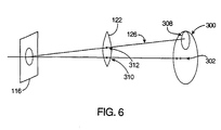
- the treatment area 300 of the cornea comprises a plurality of smaller areas ablated with individual laser pulses, such as the offset imaged apertured beam 126.
- the positions and sizes of the smaller ablated areas correspond to the values calculated in the treatment table 260.
- the decrease in curvature is accomplished by the scanning beam 126 about the cornea.
- the offset position 312 of the lens 122 is varied about the central position 310.
- This scanning produces an offset imaged apertured beam 126 with an outer portion 308.
- the beam 126 covers the center 302 of the treatment area 300 during a portion of the scanning treatment.
- a dimension of the variable aperture 116 may be varied during scanning to vary the size of the beam 126.
- the diffractive optic 12 is moved so as to rotate between pulses.
- the beam rotator 112 and diffractive optic 12 are rotated between pulses.
- the successive pulses of the scanning beam contour the desired decreased curvature according'to the treatment table 260.
- the beam 120 of Figure 3 or Figure 4 scans over a treatment area of the cornea.
- the treatment area 300 of the cornea comprises a plurality of smaller areas ablated with individual laser pulses, such as the offset imaged apertured beam 126.
- the positions and sizes of the smaller ablated areas correspond to the values calculated in the treatment table 260. More tissue must be removed from the periphery of the treatment area than from the center. This increases the radius of curvature of the cornea. The increase in curvature is accomplished by scanning the beam 126 about the cornea.
- the offset position 312 of the lens 122 is varied about the central position 310. This-scanning produces an offset images apertured beam 126 with an outer portion 308.
- the beam 126 does not cover the center 302 of the treatment area 300 during a portion of the scanning treatment.
- a dimension of variable aperture 116 may be varied during scanning to vary the size of the beam 126.
- the diffractive optic 12 is moved so as to rotate between pulses.
- the beam rotator 112 and diffractive optic 12 are rotated between pulses. Successive pulses of the scanning beam contour the cornea to the desired increased curvature according to the treatment table 260.
- variable width slit diametrically spans the treatment area of the cornea which is generally rectangular.
- the first pulse of the imaged apertured beam 126 ablates away a generally rectangular area of corneal tissue.
- Successive pulses are directed with varying width of the generally rectangular spot of the imaged apertured beam 126 which are symmetrically positioned with respect to the optical center.
- the astigmatism correcting change is effected by volumetric removal of the corneal tissue.
Landscapes
- Physics & Mathematics (AREA)
- Optics & Photonics (AREA)
- Health & Medical Sciences (AREA)
- Engineering & Computer Science (AREA)
- Ophthalmology & Optometry (AREA)
- General Physics & Mathematics (AREA)
- Heart & Thoracic Surgery (AREA)
- Animal Behavior & Ethology (AREA)
- Nuclear Medicine, Radiotherapy & Molecular Imaging (AREA)
- Veterinary Medicine (AREA)
- Surgery (AREA)
- Biomedical Technology (AREA)
- Plasma & Fusion (AREA)
- Vascular Medicine (AREA)
- Life Sciences & Earth Sciences (AREA)
- Electromagnetism (AREA)
- General Health & Medical Sciences (AREA)
- Public Health (AREA)
- Mechanical Engineering (AREA)
- Lasers (AREA)
- Laser Surgery Devices (AREA)
- Diffracting Gratings Or Hologram Optical Elements (AREA)
- Optical Elements Other Than Lenses (AREA)
- Lenses (AREA)
- Optical Radar Systems And Details Thereof (AREA)
- Semiconductor Lasers (AREA)
Applications Claiming Priority (3)
| Application Number | Priority Date | Filing Date | Title |
|---|---|---|---|
| US1584198A | 1998-01-29 | 1998-01-29 | |
| US15841 | 1998-01-29 | ||
| PCT/US1999/001281 WO1999039410A1 (en) | 1998-01-29 | 1999-01-20 | Laser delivery system and method with diffractive optic beam integration |
Publications (3)
| Publication Number | Publication Date |
|---|---|
| EP1051781A1 EP1051781A1 (en) | 2000-11-15 |
| EP1051781A4 EP1051781A4 (en) | 2002-05-15 |
| EP1051781B1 true EP1051781B1 (en) | 2005-03-23 |
Family
ID=21773938
Family Applications (1)
| Application Number | Title | Priority Date | Filing Date |
|---|---|---|---|
| EP99905449A Expired - Lifetime EP1051781B1 (en) | 1998-01-29 | 1999-01-20 | Laser delivery system with diffractive optic beam integration |
Country Status (7)
| Country | Link |
|---|---|
| EP (1) | EP1051781B1 (https=) |
| JP (1) | JP4302885B2 (https=) |
| AT (1) | ATE291787T1 (https=) |
| AU (1) | AU2560499A (https=) |
| CA (1) | CA2319122C (https=) |
| DE (1) | DE69924358T2 (https=) |
| WO (1) | WO1999039410A1 (https=) |
Families Citing this family (19)
| Publication number | Priority date | Publication date | Assignee | Title |
|---|---|---|---|---|
| US6313948B1 (en) * | 1999-08-02 | 2001-11-06 | James I. Hanna | Optical beam shaper |
| FI116918B (fi) | 2000-12-13 | 2006-03-31 | Modines Ltd Oy | Säteenmuokkaaja |
| JP2004536350A (ja) * | 2001-07-16 | 2004-12-02 | オイ アイシーエス インテリジェント コントロール システムズ リミテッド | 空間的に部分的にコヒーレントな光ビームの強度分布の回折成形 |
| US6744502B2 (en) * | 2001-09-28 | 2004-06-01 | Pe Corporation (Ny) | Shaped illumination geometry and intensity using a diffractive optical element |
| AU2003245573A1 (en) | 2002-06-19 | 2004-01-06 | Palomar Medical Technologies, Inc. | Method and apparatus for treatment of cutaneous and subcutaneous conditions |
| AUPS313802A0 (en) | 2002-06-25 | 2002-07-18 | Riancorp Pty Ltd | Laser beam homogenisers in medical applications |
| US7206132B2 (en) | 2004-08-06 | 2007-04-17 | Visx, Incorporated | Lenslet array for beam homogenization |
| US7856985B2 (en) | 2005-04-22 | 2010-12-28 | Cynosure, Inc. | Method of treatment body tissue using a non-uniform laser beam |
| US7397546B2 (en) * | 2006-03-08 | 2008-07-08 | Helicos Biosciences Corporation | Systems and methods for reducing detected intensity non-uniformity in a laser beam |
| US7586957B2 (en) | 2006-08-02 | 2009-09-08 | Cynosure, Inc | Picosecond laser apparatus and methods for its operation and use |
| US8547632B2 (en) | 2009-08-19 | 2013-10-01 | Lawrence Livermore National Security, Llc | Method and system for homogenizing diode laser pump arrays |
| US8728719B2 (en) | 2009-08-19 | 2014-05-20 | Lawrence Livermore National Security, Llc | Diffractive laser beam homogenizer including a photo-active material and method of fabricating the same |
| EP3709061B1 (en) | 2009-08-19 | 2022-12-14 | Lawrence Livermore National Security, LLC | Method of fabricating and method of using a diffractive optic |
| US9256066B2 (en) * | 2011-03-01 | 2016-02-09 | Ge Healthcare Bio-Sciences Corp. | Laser beam irradiance control systems |
| WO2013158299A1 (en) | 2012-04-18 | 2013-10-24 | Cynosure, Inc. | Picosecond laser apparatus and methods for treating target tissues with same |
| EP2973894A2 (en) | 2013-03-15 | 2016-01-20 | Cynosure, Inc. | Picosecond optical radiation systems and methods of use |
| CN109906534B (zh) * | 2016-09-20 | 2021-04-23 | 依拉迪激光有限公司 | 具有缩进孔口的激光器 |
| CN112042066A (zh) | 2018-02-26 | 2020-12-04 | 赛诺秀股份有限公司 | 调q倾腔亚纳秒激光器 |
| WO2022125289A1 (en) * | 2020-12-10 | 2022-06-16 | Cymer, Llc | Multifocal imaging with increased wavelength separation |
Family Cites Families (13)
| Publication number | Priority date | Publication date | Assignee | Title |
|---|---|---|---|---|
| US4547037A (en) | 1980-10-16 | 1985-10-15 | Regents Of The University Of Minnesota | Holographic method for producing desired wavefront transformations |
| US4732148A (en) | 1983-11-17 | 1988-03-22 | Lri L.P. | Method for performing ophthalmic laser surgery |
| US4665913A (en) | 1983-11-17 | 1987-05-19 | Lri L.P. | Method for ophthalmological surgery |
| US4770172A (en) | 1983-11-17 | 1988-09-13 | Lri L.P. | Method of laser-sculpture of the optically used portion of the cornea |
| US4669466A (en) | 1985-01-16 | 1987-06-02 | Lri L.P. | Method and apparatus for analysis and correction of abnormal refractive errors of the eye |
| JP3197375B2 (ja) * | 1992-11-07 | 2001-08-13 | 株式会社ニデック | 角膜アブレーション装置 |
| WO1994029760A1 (en) | 1993-06-04 | 1994-12-22 | Summit Technology, Inc. | Rotatable aperture apparatus and methods for selective photoablation of surfaces |
| US5376086A (en) * | 1993-10-26 | 1994-12-27 | Khoobehi; Bahram | Laser surgical method of sculpting a patient's cornea and associated intermediate controlling mask |
| US5610733A (en) | 1994-02-28 | 1997-03-11 | Digital Optics Corporation | Beam-homogenizer |
| DE4441579C1 (de) * | 1994-11-22 | 1996-05-15 | Rodenstock Instr | Vorrichtung zur Formung der Cornea |
| US5646791A (en) | 1995-01-04 | 1997-07-08 | Visx Incorporated | Method and apparatus for temporal and spatial beam integration |
| DE19619481C1 (de) * | 1996-05-14 | 1997-11-27 | Aesculap Meditec Gmbh | Verfahren und Vorrichtung zum Abtragen von Material mit einem Laserstrahl |
| US5717518A (en) * | 1996-07-22 | 1998-02-10 | Kla Instruments Corporation | Broad spectrum ultraviolet catadioptric imaging system |
-
1999
- 1999-01-20 JP JP2000529773A patent/JP4302885B2/ja not_active Expired - Lifetime
- 1999-01-20 CA CA002319122A patent/CA2319122C/en not_active Expired - Lifetime
- 1999-01-20 DE DE69924358T patent/DE69924358T2/de not_active Expired - Lifetime
- 1999-01-20 WO PCT/US1999/001281 patent/WO1999039410A1/en not_active Ceased
- 1999-01-20 EP EP99905449A patent/EP1051781B1/en not_active Expired - Lifetime
- 1999-01-20 AU AU25604/99A patent/AU2560499A/en not_active Abandoned
- 1999-01-20 AT AT99905449T patent/ATE291787T1/de not_active IP Right Cessation
Also Published As
| Publication number | Publication date |
|---|---|
| JP2002502062A (ja) | 2002-01-22 |
| WO1999039410A1 (en) | 1999-08-05 |
| AU2560499A (en) | 1999-08-16 |
| CA2319122C (en) | 2004-06-01 |
| DE69924358T2 (de) | 2006-01-19 |
| DE69924358D1 (de) | 2005-04-28 |
| EP1051781A1 (en) | 2000-11-15 |
| JP4302885B2 (ja) | 2009-07-29 |
| CA2319122A1 (en) | 1999-08-05 |
| EP1051781A4 (en) | 2002-05-15 |
| ATE291787T1 (de) | 2005-04-15 |
Similar Documents
| Publication | Publication Date | Title |
|---|---|---|
| EP1051781B1 (en) | Laser delivery system with diffractive optic beam integration | |
| US6497701B2 (en) | Method and system for ablating surfaces with partially overlapping craters having consistent curvature | |
| US6491686B2 (en) | Method and system for scanning non-overlapping patterns of laser energy with diffractive optics | |
| US4941093A (en) | Surface erosion using lasers | |
| US6706036B2 (en) | Method and apparatus for surgery of the cornea using short laser pulses having shallow ablation depth | |
| JP4854849B2 (ja) | オフセット・イメージングを使用して老眼をレーザ治療するための方法およびシステム | |
| US6816316B2 (en) | Smoothing laser beam integration using optical element motion | |
| JP3686373B2 (ja) | 一様な,広領域切除システム | |
| US6056739A (en) | Profiling the intensity distribution of optical beams | |
| JPH06277247A (ja) | 組織切除による角膜整形装置 | |
| CA2333054A1 (en) | Patient fixation system and method for laser eye surgery | |
| US7108691B2 (en) | Flexible scanning beam imaging system | |
| CA2296513A1 (en) | Systems and methods for corneal surface ablation to correct hyperopia | |
| MXPA01000379A (en) | Method and system for scanning non-overlapping patterns of laser energy with diffractive optics |
Legal Events
| Date | Code | Title | Description |
|---|---|---|---|
| PUAI | Public reference made under article 153(3) epc to a published international application that has entered the european phase |
Free format text: ORIGINAL CODE: 0009012 |
|
| 17P | Request for examination filed |
Effective date: 20000829 |
|
| AK | Designated contracting states |
Kind code of ref document: A1 Designated state(s): AT BE CH CY DE DK ES FI FR GB GR IE IT LI LU MC NL PT SE |
|
| A4 | Supplementary search report drawn up and despatched |
Effective date: 20020403 |
|
| AK | Designated contracting states |
Kind code of ref document: A4 Designated state(s): AT BE CH CY DE DK ES FI FR GB GR IE IT LI LU MC NL PT SE |
|
| RIC1 | Information provided on ipc code assigned before grant |
Free format text: 7H 01S 3/08 A, 7A 61F 9/00 B, 7H 01S 3/00 B, 7B 23K 26/06 B, 7G 02B 27/09 B |
|
| 17Q | First examination report despatched |
Effective date: 20030422 |
|
| GRAP | Despatch of communication of intention to grant a patent |
Free format text: ORIGINAL CODE: EPIDOSNIGR1 |
|
| RTI1 | Title (correction) |
Free format text: LASER DELIVERY SYSTEM WITH DIFFRACTIVE OPTIC BEAM INTEGRATION |
|
| GRAS | Grant fee paid |
Free format text: ORIGINAL CODE: EPIDOSNIGR3 |
|
| GRAA | (expected) grant |
Free format text: ORIGINAL CODE: 0009210 |
|
| AK | Designated contracting states |
Kind code of ref document: B1 Designated state(s): AT BE CH CY DE DK ES FI FR GB GR IE IT LI LU MC NL PT SE |
|
| PG25 | Lapsed in a contracting state [announced via postgrant information from national office to epo] |
Ref country code: NL Free format text: LAPSE BECAUSE OF FAILURE TO SUBMIT A TRANSLATION OF THE DESCRIPTION OR TO PAY THE FEE WITHIN THE PRESCRIBED TIME-LIMIT Effective date: 20050323 Ref country code: LI Free format text: LAPSE BECAUSE OF FAILURE TO SUBMIT A TRANSLATION OF THE DESCRIPTION OR TO PAY THE FEE WITHIN THE PRESCRIBED TIME-LIMIT Effective date: 20050323 Ref country code: FI Free format text: LAPSE BECAUSE OF FAILURE TO SUBMIT A TRANSLATION OF THE DESCRIPTION OR TO PAY THE FEE WITHIN THE PRESCRIBED TIME-LIMIT Effective date: 20050323 Ref country code: CH Free format text: LAPSE BECAUSE OF FAILURE TO SUBMIT A TRANSLATION OF THE DESCRIPTION OR TO PAY THE FEE WITHIN THE PRESCRIBED TIME-LIMIT Effective date: 20050323 Ref country code: BE Free format text: LAPSE BECAUSE OF FAILURE TO SUBMIT A TRANSLATION OF THE DESCRIPTION OR TO PAY THE FEE WITHIN THE PRESCRIBED TIME-LIMIT Effective date: 20050323 Ref country code: AT Free format text: LAPSE BECAUSE OF FAILURE TO SUBMIT A TRANSLATION OF THE DESCRIPTION OR TO PAY THE FEE WITHIN THE PRESCRIBED TIME-LIMIT Effective date: 20050323 |
|
| REG | Reference to a national code |
Ref country code: GB Ref legal event code: FG4D |
|
| REG | Reference to a national code |
Ref country code: CH Ref legal event code: EP |
|
| REG | Reference to a national code |
Ref country code: IE Ref legal event code: FG4D |
|
| REF | Corresponds to: |
Ref document number: 69924358 Country of ref document: DE Date of ref document: 20050428 Kind code of ref document: P |
|
| PG25 | Lapsed in a contracting state [announced via postgrant information from national office to epo] |
Ref country code: GR Free format text: LAPSE BECAUSE OF FAILURE TO SUBMIT A TRANSLATION OF THE DESCRIPTION OR TO PAY THE FEE WITHIN THE PRESCRIBED TIME-LIMIT Effective date: 20050623 Ref country code: DK Free format text: LAPSE BECAUSE OF FAILURE TO SUBMIT A TRANSLATION OF THE DESCRIPTION OR TO PAY THE FEE WITHIN THE PRESCRIBED TIME-LIMIT Effective date: 20050623 |
|
| PG25 | Lapsed in a contracting state [announced via postgrant information from national office to epo] |
Ref country code: ES Free format text: LAPSE BECAUSE OF FAILURE TO SUBMIT A TRANSLATION OF THE DESCRIPTION OR TO PAY THE FEE WITHIN THE PRESCRIBED TIME-LIMIT Effective date: 20050704 |
|
| NLV1 | Nl: lapsed or annulled due to failure to fulfill the requirements of art. 29p and 29m of the patents act | ||
| PG25 | Lapsed in a contracting state [announced via postgrant information from national office to epo] |
Ref country code: PT Free format text: LAPSE BECAUSE OF FAILURE TO SUBMIT A TRANSLATION OF THE DESCRIPTION OR TO PAY THE FEE WITHIN THE PRESCRIBED TIME-LIMIT Effective date: 20050907 |
|
| REG | Reference to a national code |
Ref country code: CH Ref legal event code: PL |
|
| PG25 | Lapsed in a contracting state [announced via postgrant information from national office to epo] |
Ref country code: IE Free format text: LAPSE BECAUSE OF NON-PAYMENT OF DUE FEES Effective date: 20060120 |
|
| ET | Fr: translation filed | ||
| PLBE | No opposition filed within time limit |
Free format text: ORIGINAL CODE: 0009261 |
|
| STAA | Information on the status of an ep patent application or granted ep patent |
Free format text: STATUS: NO OPPOSITION FILED WITHIN TIME LIMIT |
|
| PG25 | Lapsed in a contracting state [announced via postgrant information from national office to epo] |
Ref country code: MC Free format text: LAPSE BECAUSE OF NON-PAYMENT OF DUE FEES Effective date: 20060131 Ref country code: LU Free format text: LAPSE BECAUSE OF NON-PAYMENT OF DUE FEES Effective date: 20060131 |
|
| 26N | No opposition filed |
Effective date: 20051227 |
|
| REG | Reference to a national code |
Ref country code: IE Ref legal event code: MM4A |
|
| PG25 | Lapsed in a contracting state [announced via postgrant information from national office to epo] |
Ref country code: SE Free format text: LAPSE BECAUSE OF FAILURE TO SUBMIT A TRANSLATION OF THE DESCRIPTION OR TO PAY THE FEE WITHIN THE PRESCRIBED TIME-LIMIT Effective date: 20050623 |
|
| PG25 | Lapsed in a contracting state [announced via postgrant information from national office to epo] |
Ref country code: CY Free format text: LAPSE BECAUSE OF FAILURE TO SUBMIT A TRANSLATION OF THE DESCRIPTION OR TO PAY THE FEE WITHIN THE PRESCRIBED TIME-LIMIT Effective date: 20050323 |
|
| PGFP | Annual fee paid to national office [announced via postgrant information from national office to epo] |
Ref country code: IT Payment date: 20120123 Year of fee payment: 14 |
|
| PGFP | Annual fee paid to national office [announced via postgrant information from national office to epo] |
Ref country code: GB Payment date: 20121228 Year of fee payment: 15 |
|
| GBPC | Gb: european patent ceased through non-payment of renewal fee |
Effective date: 20140120 |
|
| PG25 | Lapsed in a contracting state [announced via postgrant information from national office to epo] |
Ref country code: GB Free format text: LAPSE BECAUSE OF NON-PAYMENT OF DUE FEES Effective date: 20140120 |
|
| REG | Reference to a national code |
Ref country code: FR Ref legal event code: PLFP Year of fee payment: 18 |
|
| PG25 | Lapsed in a contracting state [announced via postgrant information from national office to epo] |
Ref country code: IT Free format text: LAPSE BECAUSE OF NON-PAYMENT OF DUE FEES Effective date: 20140120 |
|
| REG | Reference to a national code |
Ref country code: FR Ref legal event code: PLFP Year of fee payment: 19 |
|
| REG | Reference to a national code |
Ref country code: FR Ref legal event code: PLFP Year of fee payment: 20 |
|
| PGFP | Annual fee paid to national office [announced via postgrant information from national office to epo] |
Ref country code: FR Payment date: 20171211 Year of fee payment: 20 |
|
| PGFP | Annual fee paid to national office [announced via postgrant information from national office to epo] |
Ref country code: DE Payment date: 20180110 Year of fee payment: 20 |
|
| REG | Reference to a national code |
Ref country code: DE Ref legal event code: R071 Ref document number: 69924358 Country of ref document: DE |