EP1051768B1 - Brennstoffzelle mit einem protonenleitfähigen elektrolyten - Google Patents
Brennstoffzelle mit einem protonenleitfähigen elektrolyten Download PDFInfo
- Publication number
- EP1051768B1 EP1051768B1 EP99908740A EP99908740A EP1051768B1 EP 1051768 B1 EP1051768 B1 EP 1051768B1 EP 99908740 A EP99908740 A EP 99908740A EP 99908740 A EP99908740 A EP 99908740A EP 1051768 B1 EP1051768 B1 EP 1051768B1
- Authority
- EP
- European Patent Office
- Prior art keywords
- fuel cell
- layer
- electrolyte
- anode
- palladium
- Prior art date
- Legal status (The legal status is an assumption and is not a legal conclusion. Google has not performed a legal analysis and makes no representation as to the accuracy of the status listed.)
- Expired - Lifetime
Links
Images
Classifications
-
- H—ELECTRICITY
- H01—ELECTRIC ELEMENTS
- H01M—PROCESSES OR MEANS, e.g. BATTERIES, FOR THE DIRECT CONVERSION OF CHEMICAL ENERGY INTO ELECTRICAL ENERGY
- H01M8/00—Fuel cells; Manufacture thereof
- H01M8/02—Details
- H01M8/0202—Collectors; Separators, e.g. bipolar separators; Interconnectors
- H01M8/023—Porous and characterised by the material
- H01M8/0232—Metals or alloys
-
- H—ELECTRICITY
- H01—ELECTRIC ELEMENTS
- H01M—PROCESSES OR MEANS, e.g. BATTERIES, FOR THE DIRECT CONVERSION OF CHEMICAL ENERGY INTO ELECTRICAL ENERGY
- H01M8/00—Fuel cells; Manufacture thereof
- H01M8/02—Details
- H01M8/0202—Collectors; Separators, e.g. bipolar separators; Interconnectors
- H01M8/023—Porous and characterised by the material
- H01M8/0241—Composites
- H01M8/0245—Composites in the form of layered or coated products
-
- H—ELECTRICITY
- H01—ELECTRIC ELEMENTS
- H01M—PROCESSES OR MEANS, e.g. BATTERIES, FOR THE DIRECT CONVERSION OF CHEMICAL ENERGY INTO ELECTRICAL ENERGY
- H01M8/00—Fuel cells; Manufacture thereof
- H01M8/10—Fuel cells with solid electrolytes
- H01M8/1009—Fuel cells with solid electrolytes with one of the reactants being liquid, solid or liquid-charged
-
- H—ELECTRICITY
- H01—ELECTRIC ELEMENTS
- H01M—PROCESSES OR MEANS, e.g. BATTERIES, FOR THE DIRECT CONVERSION OF CHEMICAL ENERGY INTO ELECTRICAL ENERGY
- H01M8/00—Fuel cells; Manufacture thereof
- H01M8/10—Fuel cells with solid electrolytes
- H01M8/1016—Fuel cells with solid electrolytes characterised by the electrolyte material
- H01M8/1018—Polymeric electrolyte materials
- H01M8/1041—Polymer electrolyte composites, mixtures or blends
- H01M8/1053—Polymer electrolyte composites, mixtures or blends consisting of layers of polymers with at least one layer being ionically conductive
-
- H—ELECTRICITY
- H01—ELECTRIC ELEMENTS
- H01M—PROCESSES OR MEANS, e.g. BATTERIES, FOR THE DIRECT CONVERSION OF CHEMICAL ENERGY INTO ELECTRICAL ENERGY
- H01M8/00—Fuel cells; Manufacture thereof
- H01M8/10—Fuel cells with solid electrolytes
- H01M8/1016—Fuel cells with solid electrolytes characterised by the electrolyte material
- H01M8/1018—Polymeric electrolyte materials
- H01M8/1041—Polymer electrolyte composites, mixtures or blends
- H01M8/1055—Inorganic layers on the polymer electrolytes, e.g. inorganic coatings
-
- H—ELECTRICITY
- H01—ELECTRIC ELEMENTS
- H01M—PROCESSES OR MEANS, e.g. BATTERIES, FOR THE DIRECT CONVERSION OF CHEMICAL ENERGY INTO ELECTRICAL ENERGY
- H01M8/00—Fuel cells; Manufacture thereof
- H01M8/24—Grouping of fuel cells, e.g. stacking of fuel cells
- H01M8/2455—Grouping of fuel cells, e.g. stacking of fuel cells with liquid, solid or electrolyte-charged reactants
-
- H—ELECTRICITY
- H01—ELECTRIC ELEMENTS
- H01M—PROCESSES OR MEANS, e.g. BATTERIES, FOR THE DIRECT CONVERSION OF CHEMICAL ENERGY INTO ELECTRICAL ENERGY
- H01M4/00—Electrodes
- H01M4/86—Inert electrodes with catalytic activity, e.g. for fuel cells
- H01M2004/8678—Inert electrodes with catalytic activity, e.g. for fuel cells characterised by the polarity
- H01M2004/8689—Positive electrodes
-
- H—ELECTRICITY
- H01—ELECTRIC ELEMENTS
- H01M—PROCESSES OR MEANS, e.g. BATTERIES, FOR THE DIRECT CONVERSION OF CHEMICAL ENERGY INTO ELECTRICAL ENERGY
- H01M2300/00—Electrolytes
- H01M2300/0017—Non-aqueous electrolytes
- H01M2300/0065—Solid electrolytes
- H01M2300/0082—Organic polymers
-
- H—ELECTRICITY
- H01—ELECTRIC ELEMENTS
- H01M—PROCESSES OR MEANS, e.g. BATTERIES, FOR THE DIRECT CONVERSION OF CHEMICAL ENERGY INTO ELECTRICAL ENERGY
- H01M4/00—Electrodes
- H01M4/86—Inert electrodes with catalytic activity, e.g. for fuel cells
- H01M4/90—Selection of catalytic material
- H01M4/92—Metals of platinum group
-
- H—ELECTRICITY
- H01—ELECTRIC ELEMENTS
- H01M—PROCESSES OR MEANS, e.g. BATTERIES, FOR THE DIRECT CONVERSION OF CHEMICAL ENERGY INTO ELECTRICAL ENERGY
- H01M8/00—Fuel cells; Manufacture thereof
- H01M8/04—Auxiliary arrangements, e.g. for control of pressure or for circulation of fluids
- H01M8/04082—Arrangements for control of reactant parameters, e.g. pressure or concentration
- H01M8/04089—Arrangements for control of reactant parameters, e.g. pressure or concentration of gaseous reactants
- H01M8/04119—Arrangements for control of reactant parameters, e.g. pressure or concentration of gaseous reactants with simultaneous supply or evacuation of electrolyte; Humidifying or dehumidifying
- H01M8/04156—Arrangements for control of reactant parameters, e.g. pressure or concentration of gaseous reactants with simultaneous supply or evacuation of electrolyte; Humidifying or dehumidifying with product water removal
-
- H—ELECTRICITY
- H01—ELECTRIC ELEMENTS
- H01M—PROCESSES OR MEANS, e.g. BATTERIES, FOR THE DIRECT CONVERSION OF CHEMICAL ENERGY INTO ELECTRICAL ENERGY
- H01M8/00—Fuel cells; Manufacture thereof
- H01M8/10—Fuel cells with solid electrolytes
- H01M8/1007—Fuel cells with solid electrolytes with both reactants being gaseous or vaporised
-
- H—ELECTRICITY
- H01—ELECTRIC ELEMENTS
- H01M—PROCESSES OR MEANS, e.g. BATTERIES, FOR THE DIRECT CONVERSION OF CHEMICAL ENERGY INTO ELECTRICAL ENERGY
- H01M8/00—Fuel cells; Manufacture thereof
- H01M8/10—Fuel cells with solid electrolytes
- H01M8/1016—Fuel cells with solid electrolytes characterised by the electrolyte material
- H01M8/1018—Polymeric electrolyte materials
-
- Y—GENERAL TAGGING OF NEW TECHNOLOGICAL DEVELOPMENTS; GENERAL TAGGING OF CROSS-SECTIONAL TECHNOLOGIES SPANNING OVER SEVERAL SECTIONS OF THE IPC; TECHNICAL SUBJECTS COVERED BY FORMER USPC CROSS-REFERENCE ART COLLECTIONS [XRACs] AND DIGESTS
- Y02—TECHNOLOGIES OR APPLICATIONS FOR MITIGATION OR ADAPTATION AGAINST CLIMATE CHANGE
- Y02E—REDUCTION OF GREENHOUSE GAS [GHG] EMISSIONS, RELATED TO ENERGY GENERATION, TRANSMISSION OR DISTRIBUTION
- Y02E60/00—Enabling technologies; Technologies with a potential or indirect contribution to GHG emissions mitigation
- Y02E60/30—Hydrogen technology
- Y02E60/50—Fuel cells
Definitions
- the invention relates to a fuel cell with a proton-conductive electrolyte, an anode and a cathode.
- the chemical energy stored in the fuel is stored in fuel cells converted directly into electrical energy and heat.
- fuel comes for example, pure hydrogen, methanol or natural gas
- the Fuel reacts with the oxidant, usually pure or in the fuel cell the oxygen contained in air.
- the oxidant usually pure or in the fuel cell the oxygen contained in air.
- electrical Electricity and heat also generate water in the case of carbonaceous ones
- Fuels also carbon dioxide.
- Fuel and oxidant are combined referred to as equipment.
- the single fuel cell has an anode and a cathode, between which the electrolyte is arranged.
- the fuel is in front of the anode lying anode gas space, the oxidant the cathode gas space lying in front of the cathode continuously fed to the fuel cell, the reaction products are continuously removed.
- the different types of fuel cells are usually classified based on the electrolyte used. Electrolytes that are conductive to protons are used in fuel cells, in which protons are released from the fuel at the anode are split off by electrons. The protons migrate through the proton conductive Electrolytes to the cathode where they are under the oxygen Electron absorption react to water.
- the electrolyte is a membrane made of perfluorinated Plastic used.
- semipermeable membranes are predominantly used based on poly (perfluoroalkylene) sulfonic acid, such as Nafion® R 117 used by Du Pont.
- One is used to manufacture the fuel cell Area of the electrolyte membrane with the anode material, which is usually platinum or is a platinum-ruthenium alloy, and the opposite surface coated with the cathode material, which is preferably platinum.
- the polymer membrane fuel cell can be operated with hydrogen or methanol. When using methanol, it is also referred to as a direct methanol fuel cell.
- the electrode reactions of the hydrogen-operated polymer membrane fuel cell are: Anode: H 2 ⁇ 2H + + 2 e - Cathode: O 2 + 4H + + 4e - ⁇ 2 H 2 O
- the electrode reactions of the direct methanol fuel cell are: Anode: CH 3 OH + H 2 O ⁇ CO 2 + 6 H + + 6 e - Cathode: O 2 + 4 H + + 4 e - ⁇ 2 H 2 O
- a disadvantage of these known polymer membrane fuel cells is that the electrolyte membrane not only allows the protons to pass through, but also, albeit to a lesser extent, the fuel, that is to say the molecular hydrogen (H 2 ) or the methanol molecules (CH 3 OH). This leads to a reduction in the efficiency of the fuel cell. In the case of the direct methanol fuel cell, this undesirable effect is exacerbated by the fact that the water (H 2 O) present on both the anode and cathode sides penetrates into the Nafion film, so that it swells and allows more methanol to pass through.
- H 2 O water
- the fuel cell has at least one has hydrogen-permeable barrier layer composite, the two outer layers and a core layer disposed therebetween includes each outer layer essentially made of palladium and / or an alloy based of palladium, and that the core layer consists essentially of niobium and / or tantalum and / or an alloy based on one of these metals.
- the barrier layer composite according to the invention essentially consists of the Metals palladium, niobium and tantalum, which have a high diffusivity for have atomic hydrogen, but on the other hand for larger atoms and molecules, especially impermeable to molecular hydrogen, water and methanol are. It serves to separate the anode gas space from the cathode gas space separate that the fuel is not through the electrolyte from the anode side can migrate to the cathode side. The absorption of hydrogen in the metal grid takes place with metal hydride formation.
- the three-layer structure is based on the following considerations: tantalum has a diffusivity for hydrogen atoms higher than that of Palladium lies. On the other hand, for the transfer of hydrogen from the Gas phase in the hydride phase with palladium requires a lower energy than at tantalum. However, palladium is more expensive than tantalum. These relationships also apply to niobium, which is chemically related to tantalum.
- the invention Barrier layer composite is cheaper than a diffusion layer, which is predominantly is made of palladium because the outer layers are made very thin and it absorbs the hydrogen more easily than a diffusion layer, which mainly consists of tantalum and / or niobium.
- the two outer layers which mainly consist of palladium, ensure due to the low transition energy for easy absorption of hydrogen from the gas phase in the outer layer, the subsequent transition from the outer layer to the Core layer only requires a much lower energy than the transition from the gas phase in tantalum or niobium. Because the material of the core layer is proportionate is cheap, it can be made almost any thickness and thus ensure the stability of the barrier layer composite.
- a first variant consists in the fact that the electrolyte comprises two layers, between which a barrier layer composite is arranged.
- This arrangement has the advantage that the electrolyte, the inside of the barrier layer composite contains, just like a conventional electrolyte without a barrier layer composite can be coated with the electrode materials.
- a barrier layer composite is provided between one the electrodes and the electrolyte is arranged.
- At least one of the electrodes is designed as a barrier layer composite.
- the anode to be replaced by a barrier layer composite according to the invention the Exercises function, so that in contrast to the first and second variant a separate anode layer, that is to say in addition to the barrier layer composite can be dispensed with.
- the barrier layer composite can also have further layers that between on the anode and / or cathode side the respective outer layer and the core layer are arranged.
- the Material of these additional intermediate layers can be considered, for example be selected to transition the hydrogen from the anode side Outer layer in the core layer or from the core layer in the to facilitate cathode-side outer layer.
- the intermediate layer consists essentially of one Alloy, which is essentially the main component of the neighboring Contains outer layer and the main component of the core layer. So if that two outer layers made of a palladium alloy and the core layer a niobium alloy, then for example between each outer layer and the core layer may be arranged with an intermediate layer which is essentially consists of a palladium-niobium alloy.
- the intermediate layer consists essentially of a mixture that is essentially the material of the adjacent outer layer and contains the material of the core layer.
- the intermediate layer can not just as an alloy, but also in another, of which depending on the manufacturing process used.
- the intermediate layer can be applied to the core layer by sputtering, for example, in a first step, the material of the core layer for sputtering and in a second step the material of the outer layer is used.
- a third alternative relates to the case where the core layer is essentially consists of tantalum and / or an alloy based on tantalum, and it provides that the intermediate layer consists essentially of niobium and / or Vanadium and / or an alloy based on one of these metals and / or one Palladium-tantalum alloy is made.
- the intermediate layer can consequently Have metals that do not contain the core layer and the outer layer are.
- the outer layers consist essentially of one Palladium-silver alloy, preferably with a silver content of at least 25% by weight.
- a palladium foil puffs up when hydrogen is absorbed noticeably and becomes brittle and cracked. The dimensional stability will enhanced by the addition of silver.
- the core layer is preferably a film.
- the remaining layers can pass through Coating can be applied successively to the core layer.
- the coating can by sputtering, powder coating, evaporation and the like respectively.
- the other layers can also be foils. In this If necessary, these film layers can be applied by lamination.
- the core layer is made of a material that is compared to the outer layers a higher transition energy, but also a better one Diffusivity for hydrogen, it can be thicker than any of the rest Be layers and thus for the desired stability of the barrier layer composite, the electrolyte membrane or even the entire fuel cell.
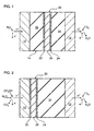
- the FIG. 1 schematically shows the structure of a polymer membrane fuel cell in a first embodiment.
- the fuel cell has an anode 10 and a cathode 12 and an electrolyte 14 located between them on.
- To the left of the anode 10 is the so-called anode gas space and to the right of cathode 12 is the cathode gas space.
- the electrolyte 14 is one proton-conducting membrane in the form of a film made of Nafion® R 117, which is on its in FIG. 1 left side with the anode 10 and on the right side with the cathode 12 is coated.
- the electrodes 10, 12 are catalytic Materials used with respect to those taking place on the electrodes 10, 12 Reactions, such as proton cleavage at the anode 10 and the recombination and reaction of the protons to water at the cathode 12 are selected. Precious metals come in as materials Question, platinum and gold are preferred, and platinum-ruthenium alloys for the anode 10.
- the electrode material is usually wet chemical deposited on the electrolyte membrane 14 or as a powder with it hot pressed.
- the electrolyte 14 is approximately 200 ⁇ m thick, the electrodes 10, 12 are approximately 100 ⁇ m thick.
- the electrolyte 14 is divided into two layers 16, 18 of equal size, between which there is a barrier layer composite 20.
- the barrier layer composite 20 separates the anode gas space from the cathode gas space.
- the composite 20 consists of two outer layers 22, 24 and a core layer lying between them 26.
- Each outer layer 22, 24 consists of palladium and is approximately 0.5 ⁇ m thick, the core layer 26, however, is an approximately 50 to 100 microns thick film from tantalum.
- the outer layers 22, 24 applied to the core layer film 26 by sputtering.
- the thickness of the barrier layer composite 20 is with regard to the barrier function selected, for cost reasons - palladium is more expensive than tantalum - the Core layer 26 should be as thick as possible in comparison to the outer layers 22, 24 should.
- the outer layers 22, 24 must be at least so thick that the hydrogen atoms Enter the core layer 26 as easily as possible and place it on the can leave the other side.
- Molecular hydrogen H 2 is continuously fed as fuel to the anode gas space.
- a hydrogen molecule H 2 is catalytically split into two protons H + and two electrons e - .
- the electrons e - are led through a pantograph, not shown, to an electrical consumer, also not shown. They reach the cathode 12 from the consumer via a second current collector (not shown).
- the protons H + generated at the anode 10 enter the anode-side electrolyte layer 16 and migrate through this to the anode-side outer layer 22. There they recombine with electrons e - to form hydrogen atoms H, which are taken up by the outer layer 22 to form palladium hydride.
- the electrons e - required for the recombination originate from the outer layer 24 on the cathode side, as will be explained below, and have migrated through the core layer 26.
- the hydrogen atoms H dissolved in the palladium of the outer layer 22 diffuse through the metal lattice up to the interface with the core layer 26, where they enter with the formation of tantalum hydride. They diffuse through the core layer 26, further with conversion into tantalum hydride into the cathode-side outer layer 24 and leave it with splitting into protons H + and electrons e - into the cathode-side electrolyte layer 18. As mentioned above, these electrons migrate through the cathode-side outer layer 24 and the core layer 26 to the anode-side outer layer 22.
- the protons H + pass through the cathode-side electrolyte layer 18 to the cathode 12, where they are in contact with one another via the outer consumer circuit Combine the supplied electrons e and the oxygen O 2 , which is continuously supplied to the cathode gas space, to form water H 2 O.
- the reaction product water H 2 O is continuously discharged from the cathode gas space.
- the barrier layer composite 20 thus only allows atomic hydrogen H to pass through, while it serves as a barrier to the molecular hydrogen H 2 .
- FIG. 2 shows a polymer membrane fuel cell in a corresponding second embodiment, in which the barrier layer composite 20 is attached to the anode side of a single-layer electrolyte 14.
- This arrangement is particularly suitable for the direct methanol fuel cell, since it prevents the water H 2 O supplied to the anode gas space from penetrating into the electrolyte 14 and swelling.
- the anode-side outer layer 22 adjoins the anode 10
- the electrolyte 14 only adjoins the cathode-side outer layer 24.
- Methanol CH 3 OH and water H 2 O are continuously fed into the anode gas space and react at the anode to form carbon dioxide CO 2 , protons H + and electrons e - .
- the electrons e - are conducted to the cathode 12 through a consumer circuit (not shown).
- the protons H + with recombination with electrons e - which originate from the cathode-side outer layer 24, enter the anode-side outer layer 22 with hydride formation, diffuse, as described above, through the barrier layer composite 20 and arrive as protons H + with elimination of electrons e - From the cathode-side outer layer 24 in the electrolyte 14.
- the protons H + migrate through the electrolyte 14 to the cathode 12, where they react with the electrons e - from the consumer circuit and with the oxygen O 2 continuously supplied to the cathode gas space to form water H 2 O. that is continuously derived.
- the barrier layer composite 20 thus only allows atomic hydrogen H to pass through, while it serves as a barrier between the two gas spaces for larger molecules, in particular methanol CH 3 OH and water H 2 O.
- the in the FIG. 2 can be manufactured as follows.
- the two outer layers 22, 24, for example, are first applied to the core layer 26 by sputtering.
- Outer layer 22 applied the anode 10, which is also done by sputtering can.
- the electrolyte 14 is applied to the outer layer 24 on the cathode side upset.
- the surface of the electrolyte opposite the outer layer 24 14 is coated with the cathode 12, for example by sputtering or chemical wet deposition.
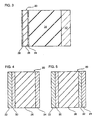
- the FIG. 3 shows a polymer membrane fuel cell in a third embodiment, which is a modification of the in FIG. 2 shown fuel cell represents.
- the modification is that the anode layer 10 of the fuel cell the FIG. 2 and the anode-side outer layer 22 is missing instead the FIG. 2 serves as an anode; so to speak, the outer layer 22 of FIG. 2nd and the anode 10 of FIG. 2 combined in a combination layer 28.
- This combination layer 28 consists essentially of a mixture that as the first component, the material of the anode 10 of FIG. 2, for example Platinum, and as a second component the material of the outer layer 22 of FIG. 2, for example palladium.
- the mixture can be an alloy of these metals, but other types of mixtures are also possible.
- the Combination layer 28 can be sputtered onto core layer 26 are used as a target material, a platinum-palladium alloy becomes.
- the outer layer 22 can, however, also remain unchanged, that is to say without the addition of platinum be used as an anode, since the anode reactions also with palladium as Run off catalyst.
- the cathode side serves Outer layer 24 of FIG. 2, alone or as a combination layer, as a cathode.
- the two outer layers 22, 24 are also made of different materials can exist.
- the Palladium content may be different, or there may be an outer layer made of palladium and the other of a palladium-silver alloy.
- the core layer 26 does not necessarily have to contain tantalum as the main component exhibit. Niobium or a mixture also comes for the main ingredient made of tantalum and niobium as well as niobium, tantalum and niobium-tantalum alloys in Question.
- the core layer 26 can also contain additives in the outer layers 22, 24 have contained substances. Furthermore, there can be between each outer layer 22, 24 and the core layer 26 are at least one further intermediate layer.
- FIG. 4 shows a modification of the junction composite 20 which is shown in FIG the in the FIG. 1, 2 and 3 fuel cells shown is used.
- the intermediate layer 30 can essentially consist of an alloy, which is essentially the main component of the neighboring, anode-side outer layer 22 and the main component of the Contains core layer 26, but it can also consist essentially of a mixture exist, which are essentially the material of the adjacent, anode-side Outer layer 22 and the material of the core layer 26 contains.
- the core layer 26 made of a tantalum alloy and the anode side Outer layer 22 consists of a palladium-silver alloy
- that can Material for the intermediate layer 30 may be a palladium-tantalum alloy, however also, for example, a mixture, preferably an alloy, of the palladium-silver alloy and the tantalum alloy.
- intermediate layer 30 Other materials can also be used for the intermediate layer 30, as long as they offer sufficient diffusivity for the hydrogen atoms. So can for the core layer 26 and the outer layer 22 of the previous example the intermediate layer 30 also consists essentially of niobium or a niobium alloy or vanadium or a vanadium alloy or a mixture, preferably alloy, of two or more of these substances. Also between the cathode-side outer layer 24 and the core layer 26 can be similar Intermediate layers 32 can be arranged as shown in FIG. 5 is shown.
Landscapes
- Chemical & Material Sciences (AREA)
- Sustainable Energy (AREA)
- Electrochemistry (AREA)
- Engineering & Computer Science (AREA)
- Manufacturing & Machinery (AREA)
- Sustainable Development (AREA)
- General Chemical & Material Sciences (AREA)
- Chemical Kinetics & Catalysis (AREA)
- Life Sciences & Earth Sciences (AREA)
- Composite Materials (AREA)
- Inorganic Chemistry (AREA)
- Inert Electrodes (AREA)
- Addition Polymer Or Copolymer, Post-Treatments, Or Chemical Modifications (AREA)
- Conductive Materials (AREA)
- Fuel Cell (AREA)
Description
- FIG. 1
- ist ein schematischer Querschnitt durch eine Polymermembran-Brennstoffzelle in einer ersten Ausführungsform;
- FIG. 2
- ist ein schematischer Querschnitt durch eine Polymermembran-Brennstoffzelle in einer zweiten Ausführungsform;
- FIG. 3
- ist ein schematischer Querschnitt durch eine Polymermembran-Brennstoffzelle in einer dritten Ausführungsform; und
- FIG. 4 und 5
- zeigen in einem vergrößerten Ausschnitt Abwandlungen des Sperrschichtverbunds der in den FIG. 1 bis 3 gezeigten Brennstoffzellen.
Claims (13)
- Brennstoffzelle mit einem protonenleitfähigen Elektrolyten (14), einer Anode (10) und einer Kathode (12), dadurch gekennzeichnet, daß sie wenigstens einen wasserstoffdurchlässigen Sperrschichtverbund (20) aufweist, der zwei Außenschichten (22, 24) und eine zwischen diesen angeordnete Kernschicht (26) umfaßt, daß jede Außenschicht (22, 24) aus Palladium und/oder einer Legierung auf Basis von Palladium besteht, und daß die Kernschicht (26) aus Niob und/oder Tantal und/oder einer Legierung auf Basis eines dieser Metalle besteht, wobei der Sperrschichtverbund (20) in der Brennstoffzelle verhindert, daß Brennstoff durch den protonleitfähigen Elektrolyten (14) von der Anodenseite zur Kathodenseite wandert.
- Brennstoffzelle nach Anspruch 1, dadurch gekennzeichnet, daß der Elektrolyt (14) zwei Lagen (16, 18) umfaßt, zwischen denen ein Sperrschichtverbund (20) angeordnet ist.
- Brennstoffzelle nach Anspruch 1 oder 2, dadurch gekennzeichnet, daß ein Sperrschichtverbund (20) zwischen einer der Elektroden (10, 12) und dem Elektrolyten (14) angeordnet ist.
- Brennstoffzelle nach einem der vorhergehenden Ansprüche, dadurch gekennzeichnet, daß wenigstens eine der Elektroden (10, 12) als Sperrschichtverbund (20) ausgebildet ist.
- Brennstoffzelle nach einem der vorhergehenden Ansprüche, dadurch gekennzeichnet, daß zumindest zwischen einer der Außenschichten (22, 24) und der Kernschicht (26) wenigstens eine Zwischenschicht (30, 32) angeordnet ist.
- Brennstoffzelle nach Anspruch 5, dadurch gekennzeichnet, daß die Zwischenschicht (30, 32) aus einer Legierung besteht, die den Hauptbestandteil der benachbarten Außenschicht (22, 24) und den Hauptbestandteil der Kernschicht (26) enthält.
- Brennstoffzelle nach Anspruch 5, dadurch gekennzeichnet, daß die Zwischenschicht (30, 32) aus einer Mischung besteht, die das Material der benachbarten Außenschicht (22, 24) und das Material der Kernschicht (26) enthält.
- Brennstoffzelle nach Anspruch 5, dadurch gekennzeichnet, daß die Kernschicht (26) aus Tantal und/oder einer Legierung auf Basis von Tantal besteht, und daß die Zwischenschicht (30, 32) aus Niob und/oder Vanadium und/oder einer Legierung auf Basis eines dieser Metalle und/oder einer Palladium-Tantal-Legierung besteht.
- Brennstoffzelle nach einem der vorhergehenden Ansprüche, dadurch gekennzeichnet, daß wenigstens eine der Außenschichten (22, 24) aus einer Palladium-Silber-Legierung besteht.
- Brennstoffzelle nach Anspruch 9, dadurch gekennzeichnet, daß der Gehalt an Silber wenigstens 25 Gew.-% beträgt.
- Brennstoffzelle nach einem der vorhergehenden Ansprüche, dadurch gekennzeichnet, daß die Kernschicht (26) eine Folie ist.
- Brennstoffzelle nach einem der vorhergehenden Ansprüche, dadurch gekennzeichnet, daß wenigstens eine der Außenschichten (22, 24) eine Folie ist.
- Brennstoffzelle nach einem der vorhergehenden Ansprüche, dadurch gekennzeichnet, daß die Kernschicht (26) dicker als jede der übrigen Schichten (22, 24, 30, 32) ist.
Applications Claiming Priority (3)
| Application Number | Priority Date | Filing Date | Title |
|---|---|---|---|
| DE19803132 | 1998-01-28 | ||
| DE19803132A DE19803132C1 (de) | 1998-01-28 | 1998-01-28 | Brennstoffzelle mit einem protonenleitfähigen Elektrolyten |
| PCT/DE1999/000108 WO1999039398A1 (de) | 1998-01-28 | 1999-01-14 | Brennstoffzelle mit einem protonenleitfähigen elektrolyten |
Publications (2)
| Publication Number | Publication Date |
|---|---|
| EP1051768A1 EP1051768A1 (de) | 2000-11-15 |
| EP1051768B1 true EP1051768B1 (de) | 2001-10-04 |
Family
ID=7855844
Family Applications (1)
| Application Number | Title | Priority Date | Filing Date |
|---|---|---|---|
| EP99908740A Expired - Lifetime EP1051768B1 (de) | 1998-01-28 | 1999-01-14 | Brennstoffzelle mit einem protonenleitfähigen elektrolyten |
Country Status (5)
| Country | Link |
|---|---|
| EP (1) | EP1051768B1 (de) |
| AT (1) | ATE206561T1 (de) |
| CA (1) | CA2320210C (de) |
| DE (2) | DE19803132C1 (de) |
| WO (1) | WO1999039398A1 (de) |
Families Citing this family (16)
| Publication number | Priority date | Publication date | Assignee | Title |
|---|---|---|---|---|
| US6720105B2 (en) * | 1999-11-17 | 2004-04-13 | Neah Power Systems, Inc. | Metallic blocking layers integrally associated with fuel cell electrode structures and fuel cell electrode stack assemblies |
| FR2814857B1 (fr) * | 2000-10-04 | 2004-11-26 | Sagem | Micropiles a combustible notamment utilisees dans les dispositifs electroniques portables, dans les equipements automobiles et dans les dispositifs de telecommunication |
| DE10057161C2 (de) * | 2000-11-16 | 2003-08-21 | Heraeus Gmbh W C | Niob-Legierung und eine daraus hergestellte Wasserstoffpermeationsmembran |
| FR2838870B1 (fr) | 2002-04-23 | 2004-05-28 | Commissariat Energie Atomique | Element de base de pile a combustible limitant la traversee de l'electrolyte par le methanol |
| JP4079016B2 (ja) | 2002-08-28 | 2008-04-23 | トヨタ自動車株式会社 | 中温域で作動可能な燃料電池 |
| EP1619736A4 (de) * | 2003-03-18 | 2008-06-04 | Toyota Motor Co Ltd | Brennstoffzelle und verfahren zur herstellung einer elektrolytmembran für eine brennstoffzelle |
| US20040197626A1 (en) * | 2003-04-01 | 2004-10-07 | Yoocharn Jeon | Composite electrolyte for fuel cell |
| DE102004020705B4 (de) * | 2004-04-28 | 2011-11-24 | Zentrum für Sonnenenergie- und Wasserstoff-Forschung Baden-Württemberg Gemeinnützige Stiftung | Vorrichtung zum Rekombinieren von gasförmigem Wasserstoff und Sauerstoff sowie deren Verwendung zur Rekombination von wasserstoff- und sauerstoffhaltigen Gasen |
| US20060068253A1 (en) * | 2004-09-29 | 2006-03-30 | Proton Energy Systems, Inc | Gas barrier for electrochemical cells |
| US20060083852A1 (en) * | 2004-10-18 | 2006-04-20 | Yoocham Jeon | Fuel cell apparatus and method of manufacture thereof |
| US7749637B2 (en) | 2005-09-19 | 2010-07-06 | Gm Global Technology Operations, Inc. | Water blocking layer and wicking reservoir for PEMFC |
| US7368200B2 (en) * | 2005-12-30 | 2008-05-06 | Tekion, Inc. | Composite polymer electrolyte membranes and electrode assemblies for reducing fuel crossover in direct liquid feed fuel cells |
| DE102006012907A1 (de) * | 2006-03-10 | 2007-09-13 | Deutsches Zentrum für Luft- und Raumfahrt e.V. | Elektroden-Membran-Einheit und Brennstoffzelle |
| JP2007250265A (ja) * | 2006-03-14 | 2007-09-27 | Toyota Motor Corp | 燃料電池用補強型電解質膜、その製造方法、燃料電池用膜−電極接合体、及びそれを備えた固体高分子型燃料電池 |
| DE102006062251A1 (de) * | 2006-12-22 | 2008-06-26 | Volkswagen Ag | Membran-Elektroden-Einheit für Brennstoffzellen und Brennstoffzelle |
| EP4114584A4 (de) | 2020-03-06 | 2025-06-11 | JTEC Energy, Inc. | Energiewandler mit dampfkonzentration |
Family Cites Families (3)
| Publication number | Priority date | Publication date | Assignee | Title |
|---|---|---|---|---|
| DE4241150C1 (de) * | 1992-12-07 | 1994-06-01 | Fraunhofer Ges Forschung | Elektrodenmembran-Verbund, Verfahren zu dessen Herstellung sowie dessen Verwendung |
| EP0631337B1 (de) * | 1993-06-18 | 2000-07-12 | Tanaka Kikinzoku Kogyo K.K. | Elektrochemische Zelle die eine polymere Feststoff-Elektrolytzusammensetzung enthält. |
| WO1996029752A1 (en) * | 1995-03-20 | 1996-09-26 | E.I. Du Pont De Nemours And Company | Membranes containing inorganic fillers and membrane and electrode assemblies and electrochemical cells employing same |
-
1998
- 1998-01-28 DE DE19803132A patent/DE19803132C1/de not_active Expired - Fee Related
-
1999
- 1999-01-14 CA CA002320210A patent/CA2320210C/en not_active Expired - Fee Related
- 1999-01-14 AT AT99908740T patent/ATE206561T1/de active
- 1999-01-14 WO PCT/DE1999/000108 patent/WO1999039398A1/de not_active Ceased
- 1999-01-14 DE DE59900295T patent/DE59900295D1/de not_active Expired - Lifetime
- 1999-01-14 EP EP99908740A patent/EP1051768B1/de not_active Expired - Lifetime
Also Published As
| Publication number | Publication date |
|---|---|
| CA2320210A1 (en) | 1999-08-05 |
| ATE206561T1 (de) | 2001-10-15 |
| EP1051768A1 (de) | 2000-11-15 |
| WO1999039398A1 (de) | 1999-08-05 |
| CA2320210C (en) | 2008-06-10 |
| DE19803132C1 (de) | 1999-04-01 |
| DE59900295D1 (de) | 2001-11-08 |
Similar Documents
| Publication | Publication Date | Title |
|---|---|---|
| EP0934606B1 (de) | Elektroden-elektrolyt-einheit für eine brennstoffzelle | |
| EP1051768B1 (de) | Brennstoffzelle mit einem protonenleitfähigen elektrolyten | |
| DE60032577T2 (de) | Kompositelektroden für festkörperelektrochemische vorrichtungen | |
| DE69622747T2 (de) | Vorrichtung zur verringerung des reaktandenübertritts in einer elektrochemischen brennstoffzelle | |
| DE19502391C1 (de) | Membranelektrodeneinheit gebildet durch die Zusammenfassung von flächigen Einzelzellen und deren Verwendung | |
| DE69600422T2 (de) | Elektrode mit zwei Elektrokatalysatoren | |
| DE102008046403B4 (de) | Sauerstoffentwicklungsreaktionskatalysatoren enthaltende Elektroden | |
| DE60205090T2 (de) | Verfahren zur Herstellung von Membran-Elektroden-Einheiten unter Verwendung von mit katalysator beschichteten Membranen und Klebstoffen | |
| DE102008003197B4 (de) | Membranelektrodeneinheit und Verfahren zum Mindern von Elektrodendegradation während Einschalt- und Abschaltzyklen | |
| DE102008034353B4 (de) | Membranelektrodenanordnung und deren Verwendung | |
| DE10151458A1 (de) | Verfahren zur Herstellung von Membranelektrolytbaugruppen | |
| DE19611510A1 (de) | Gasdiffusionselektrode für Membranbrennstoffzellen und Verfahren zu ihrer Herstellung | |
| DE112005001378B4 (de) | Membranelektrodenanordnung | |
| EP1261057A1 (de) | Verfahren zur Herstellung einer Membran-Elektrodeneinheit und dadurch hergestellte Membran-Elektrodeneinheit | |
| EP1636865B1 (de) | Membran-elektroden-einheit für direkt methanol-brennstoffzellen und verfahren zu ihrer herstellung | |
| DE102012014168B4 (de) | Zweischichtiger Kathodenkatalysator-Aufbau für Festpolymer-Elektrolyt-Brennstoffzelle | |
| DE102015118426A1 (de) | Membranelektrodenanordnung und Brennstoffzelle | |
| DE102018213148A1 (de) | Schichtaufbau für eine Brennstoffzelle und Verfahren zur Herstellung eines solchen Schichtaufbaus | |
| DE112004001685T5 (de) | Berücksichtigen einer MEA-Ausfallbetriebsart durch Steuerung einer MEA-Katalysatorschichtüberlappung | |
| DE10052189B4 (de) | Mehrschichtige Gasdiffusionselektrode einer Polymerelektrolytmembran-Brennstoffzelle, Membranelektrodenanordnung, Verfahren zur Herstellung einer Gasdiffusionselektrode und einer Membranelektrodenanordnung sowie Verwendung der Membranelektrodenanordnung | |
| EP1833112B1 (de) | Elektroden-Membran-Einheit und Brennstoffzelle | |
| EP2652823A1 (de) | Membran-elektroden-anordnung mit zwei deckschichten | |
| DE102023205612A1 (de) | Elektrochemische Zelle mit Elektrokatalysator-Doppelschichtstruktur Graphen-basiertes Material umfassend | |
| WO2000039876A2 (de) | Elektroden-elektrolyt-einheit für eine brennstoffzelle | |
| EP4004999B1 (de) | Membranelektrodenanordnung und brennstoffzelle |
Legal Events
| Date | Code | Title | Description |
|---|---|---|---|
| PUAI | Public reference made under article 153(3) epc to a published international application that has entered the european phase |
Free format text: ORIGINAL CODE: 0009012 |
|
| 17P | Request for examination filed |
Effective date: 20000720 |
|
| AK | Designated contracting states |
Kind code of ref document: A1 Designated state(s): AT BE CH CY DE DK ES FI FR GB GR IE IT LI LU MC NL PT SE |
|
| GRAG | Despatch of communication of intention to grant |
Free format text: ORIGINAL CODE: EPIDOS AGRA |
|
| 17Q | First examination report despatched |
Effective date: 20010209 |
|
| GRAG | Despatch of communication of intention to grant |
Free format text: ORIGINAL CODE: EPIDOS AGRA |
|
| GRAH | Despatch of communication of intention to grant a patent |
Free format text: ORIGINAL CODE: EPIDOS IGRA |
|
| GRAH | Despatch of communication of intention to grant a patent |
Free format text: ORIGINAL CODE: EPIDOS IGRA |
|
| GRAA | (expected) grant |
Free format text: ORIGINAL CODE: 0009210 |
|
| AK | Designated contracting states |
Kind code of ref document: B1 Designated state(s): AT BE CH CY DE DK ES FI FR GB GR IE IT LI LU MC NL PT SE |
|
| PG25 | Lapsed in a contracting state [announced via postgrant information from national office to epo] |
Ref country code: NL Free format text: LAPSE BECAUSE OF FAILURE TO SUBMIT A TRANSLATION OF THE DESCRIPTION OR TO PAY THE FEE WITHIN THE PRESCRIBED TIME-LIMIT Effective date: 20011004 Ref country code: IT Free format text: LAPSE BECAUSE OF FAILURE TO SUBMIT A TRANSLATION OF THE DESCRIPTION OR TO PAY THE FEE WITHIN THE PRESCRIBED TIME-LIMIT;WARNING: LAPSES OF ITALIAN PATENTS WITH EFFECTIVE DATE BEFORE 2007 MAY HAVE OCCURRED AT ANY TIME BEFORE 2007. THE CORRECT EFFECTIVE DATE MAY BE DIFFERENT FROM THE ONE RECORDED. Effective date: 20011004 Ref country code: FI Free format text: LAPSE BECAUSE OF FAILURE TO SUBMIT A TRANSLATION OF THE DESCRIPTION OR TO PAY THE FEE WITHIN THE PRESCRIBED TIME-LIMIT Effective date: 20011004 |
|
| REF | Corresponds to: |
Ref document number: 206561 Country of ref document: AT Date of ref document: 20011015 Kind code of ref document: T |
|
| REG | Reference to a national code |
Ref country code: CH Ref legal event code: EP |
|
| REF | Corresponds to: |
Ref document number: 59900295 Country of ref document: DE Date of ref document: 20011108 |
|
| REG | Reference to a national code |
Ref country code: IE Ref legal event code: FG4D Free format text: GERMAN |
|
| REG | Reference to a national code |
Ref country code: GB Ref legal event code: IF02 |
|
| PG25 | Lapsed in a contracting state [announced via postgrant information from national office to epo] |
Ref country code: SE Free format text: LAPSE BECAUSE OF FAILURE TO SUBMIT A TRANSLATION OF THE DESCRIPTION OR TO PAY THE FEE WITHIN THE PRESCRIBED TIME-LIMIT Effective date: 20020104 Ref country code: PT Free format text: LAPSE BECAUSE OF FAILURE TO SUBMIT A TRANSLATION OF THE DESCRIPTION OR TO PAY THE FEE WITHIN THE PRESCRIBED TIME-LIMIT Effective date: 20020104 Ref country code: DK Free format text: LAPSE BECAUSE OF FAILURE TO SUBMIT A TRANSLATION OF THE DESCRIPTION OR TO PAY THE FEE WITHIN THE PRESCRIBED TIME-LIMIT Effective date: 20020104 |
|
| PG25 | Lapsed in a contracting state [announced via postgrant information from national office to epo] |
Ref country code: GR Free format text: LAPSE BECAUSE OF FAILURE TO SUBMIT A TRANSLATION OF THE DESCRIPTION OR TO PAY THE FEE WITHIN THE PRESCRIBED TIME-LIMIT Effective date: 20020105 |
|
| GBT | Gb: translation of ep patent filed (gb section 77(6)(a)/1977) |
Effective date: 20020108 |
|
| PG25 | Lapsed in a contracting state [announced via postgrant information from national office to epo] |
Ref country code: CY Free format text: LAPSE BECAUSE OF FAILURE TO SUBMIT A TRANSLATION OF THE DESCRIPTION OR TO PAY THE FEE WITHIN THE PRESCRIBED TIME-LIMIT Effective date: 20020131 |
|
| NLV1 | Nl: lapsed or annulled due to failure to fulfill the requirements of art. 29p and 29m of the patents act | ||
| PG25 | Lapsed in a contracting state [announced via postgrant information from national office to epo] |
Ref country code: ES Free format text: LAPSE BECAUSE OF FAILURE TO SUBMIT A TRANSLATION OF THE DESCRIPTION OR TO PAY THE FEE WITHIN THE PRESCRIBED TIME-LIMIT Effective date: 20020430 |
|
| RAP2 | Party data changed (patent owner data changed or rights of a patent transferred) |
Owner name: FORSCHUNGSZENTRUM JUELICH GMBH |
|
| PLBE | No opposition filed within time limit |
Free format text: ORIGINAL CODE: 0009261 |
|
| STAA | Information on the status of an ep patent application or granted ep patent |
Free format text: STATUS: NO OPPOSITION FILED WITHIN TIME LIMIT |
|
| 26N | No opposition filed | ||
| PGFP | Annual fee paid to national office [announced via postgrant information from national office to epo] |
Ref country code: MC Payment date: 20040122 Year of fee payment: 6 |
|
| PGFP | Annual fee paid to national office [announced via postgrant information from national office to epo] |
Ref country code: LU Payment date: 20040126 Year of fee payment: 6 |
|
| PGFP | Annual fee paid to national office [announced via postgrant information from national office to epo] |
Ref country code: BE Payment date: 20040127 Year of fee payment: 6 |
|
| PGFP | Annual fee paid to national office [announced via postgrant information from national office to epo] |
Ref country code: CH Payment date: 20040129 Year of fee payment: 6 |
|
| PG25 | Lapsed in a contracting state [announced via postgrant information from national office to epo] |
Ref country code: LU Free format text: LAPSE BECAUSE OF NON-PAYMENT OF DUE FEES Effective date: 20050114 |
|
| PG25 | Lapsed in a contracting state [announced via postgrant information from national office to epo] |
Ref country code: MC Free format text: LAPSE BECAUSE OF NON-PAYMENT OF DUE FEES Effective date: 20050131 Ref country code: LI Free format text: LAPSE BECAUSE OF NON-PAYMENT OF DUE FEES Effective date: 20050131 Ref country code: CH Free format text: LAPSE BECAUSE OF NON-PAYMENT OF DUE FEES Effective date: 20050131 Ref country code: BE Free format text: LAPSE BECAUSE OF NON-PAYMENT OF DUE FEES Effective date: 20050131 |
|
| BERE | Be: lapsed |
Owner name: FORSCHUNGSZENTRUM *JULICH G.M.B.H. Effective date: 20050131 |
|
| REG | Reference to a national code |
Ref country code: CH Ref legal event code: PL |
|
| BERE | Be: lapsed |
Owner name: FORSCHUNGSZENTRUM *JULICH G.M.B.H. Effective date: 20050131 |
|
| PGFP | Annual fee paid to national office [announced via postgrant information from national office to epo] |
Ref country code: IE Payment date: 20110120 Year of fee payment: 13 |
|
| PGFP | Annual fee paid to national office [announced via postgrant information from national office to epo] |
Ref country code: AT Payment date: 20110120 Year of fee payment: 13 Ref country code: DE Payment date: 20110104 Year of fee payment: 13 Ref country code: FR Payment date: 20110201 Year of fee payment: 13 |
|
| PGFP | Annual fee paid to national office [announced via postgrant information from national office to epo] |
Ref country code: GB Payment date: 20110121 Year of fee payment: 13 |
|
| GBPC | Gb: european patent ceased through non-payment of renewal fee |
Effective date: 20120114 |
|
| REG | Reference to a national code |
Ref country code: FR Ref legal event code: ST Effective date: 20120928 |
|
| REG | Reference to a national code |
Ref country code: IE Ref legal event code: MM4A |
|
| PG25 | Lapsed in a contracting state [announced via postgrant information from national office to epo] |
Ref country code: DE Free format text: LAPSE BECAUSE OF NON-PAYMENT OF DUE FEES Effective date: 20120801 Ref country code: GB Free format text: LAPSE BECAUSE OF NON-PAYMENT OF DUE FEES Effective date: 20120114 |
|
| REG | Reference to a national code |
Ref country code: DE Ref legal event code: R119 Ref document number: 59900295 Country of ref document: DE Effective date: 20120801 |
|
| REG | Reference to a national code |
Ref country code: AT Ref legal event code: MM01 Ref document number: 206561 Country of ref document: AT Kind code of ref document: T Effective date: 20120114 |
|
| PG25 | Lapsed in a contracting state [announced via postgrant information from national office to epo] |
Ref country code: FR Free format text: LAPSE BECAUSE OF NON-PAYMENT OF DUE FEES Effective date: 20120131 |
|
| PG25 | Lapsed in a contracting state [announced via postgrant information from national office to epo] |
Ref country code: AT Free format text: LAPSE BECAUSE OF NON-PAYMENT OF DUE FEES Effective date: 20120114 Ref country code: IE Free format text: LAPSE BECAUSE OF NON-PAYMENT OF DUE FEES Effective date: 20120114 |