EP1050714B1 - Boiler controlling device - Google Patents
Boiler controlling device Download PDFInfo
- Publication number
- EP1050714B1 EP1050714B1 EP00420086A EP00420086A EP1050714B1 EP 1050714 B1 EP1050714 B1 EP 1050714B1 EP 00420086 A EP00420086 A EP 00420086A EP 00420086 A EP00420086 A EP 00420086A EP 1050714 B1 EP1050714 B1 EP 1050714B1
- Authority
- EP
- European Patent Office
- Prior art keywords
- speed
- boiler
- fan
- contact
- firing
- Prior art date
- Legal status (The legal status is an assumption and is not a legal conclusion. Google has not performed a legal analysis and makes no representation as to the accuracy of the status listed.)
- Revoked
Links
Images

Classifications
-
- F—MECHANICAL ENGINEERING; LIGHTING; HEATING; WEAPONS; BLASTING
- F23—COMBUSTION APPARATUS; COMBUSTION PROCESSES
- F23N—REGULATING OR CONTROLLING COMBUSTION
- F23N1/00—Regulating fuel supply
- F23N1/02—Regulating fuel supply conjointly with air supply
- F23N1/022—Regulating fuel supply conjointly with air supply using electronic means
-
- F—MECHANICAL ENGINEERING; LIGHTING; HEATING; WEAPONS; BLASTING
- F23—COMBUSTION APPARATUS; COMBUSTION PROCESSES
- F23N—REGULATING OR CONTROLLING COMBUSTION
- F23N2233/00—Ventilators
- F23N2233/06—Ventilators at the air intake
- F23N2233/08—Ventilators at the air intake with variable speed
-
- F—MECHANICAL ENGINEERING; LIGHTING; HEATING; WEAPONS; BLASTING
- F23—COMBUSTION APPARATUS; COMBUSTION PROCESSES
- F23N—REGULATING OR CONTROLLING COMBUSTION
- F23N2237/00—Controlling
- F23N2237/10—High or low fire
Definitions
- the present invention relates to a regulation device for a boiler, in particular a central heating boiler.
- a conventional heating system includes a boiler, a three-way valve, two pumps, as well as, of course, the radiators supplied from the boiler.
- the three-way valve distributes the hot water produced at the level of the boiler by sending a quantity more or less hot water to the radiators.
- This valve is controlled by a device that receives temperature information (outside temperature, room temperature, water temperature at boiler outlet, etc.).
- a pump is necessary for the circulation of water to the radiators and another for the return water circulation directly to the boiler.
- boilers called "two-stage" boilers.
- Such a boiler can operate either at 100% of its capacity, or with a predetermined intermediate load. We can thus avoid many ignitions and stops and of the boiler. However, we still have constraints relatively high due to sudden variations in engine speed boiler.
- the object of the present invention is therefore to provide the means for modulating the power of a boiler from a regulation of standard heating for two-stage boilers to avoid variations abrupt revs, upon ignition and then in service mode.
- the device it offers is a regulation for a boiler, comprising a fan driven by a variable speed motor, this device comprising a first contact electric and means for varying the rotation speed of the fan, during the ignition phase of the boiler, between positions stop, walk at a first speed which corresponds to the flow of pre-ventilation, or walking at a second pace which corresponds to ignition rate, the device being characterized in that it comprises a second electrical contact provided to vary, after switching on the boiler and during operation in service mode, the rotation speed of the fan between a first minimum speed X and a second speed MAX maximum, these variations taking place gradually thanks to the means to vary the fan speed when the second contact electric is activated.
- This regulation device makes it possible to maintain the temperature of the water leaving the boiler at a temperature very close to a temperature setpoint. Thanks to the progressive variation of the fan speed, and therefore consequently of the power of the boiler, the constraints by rapid variations in temperature are avoided. In addition, such a device allows to limit the ignition and shutdown of the boiler. These are repeated only in cases where the hot water requirements are low, which does not represents only a small part of the operation of a boiler in general.
- the means provided for acting gradually on the fan speed include a modulator of microprocessor frequency. It is then possible to store in the microprocessor software that controls the fan speed according to data entered beforehand.
- This frequency modulator is advantageously controlled from only from the open or closed state of the electrical contacts.
- the outside temperatures and water produced by the boiler are used as for them for controlling the electrical contacts.
- the regulation according to the invention may include a third electrical contact, also designed to switch the fan from its first to its second pace or vice versa; means for gradually varying the fan speed when the third electrical contact is activated are then also provided, and the speed variation is different according to that it is controlled by one or other of the electrical contacts.
- the present invention also relates to a boiler for central heating which includes a regulating device according to the invention.
- the invention also provides a method of regulation for a boiler comprising a fan driven by a variable speed motor, the boiler being provided with a regulation device comprising a first boiler with a fan driven by a speed motor variable, the boiler being provided with a regulating device comprising a first electrical contact which controls the starting and stopping of the fan and a second electrical contact which allows you to choose the speed of the fan between two predetermined speeds.
- the fan is first blocked by injecting a weak current in the motor, then the fan goes at a speed predetermined pre-ventilation for a predetermined period before switch to ignition speed for a period of time also predetermined, an action on the second contact having no effect on the fan during this entire ignition phase.
- the regulation device is intended for central heating comprising a boiler supplying several radiators.
- the boiler is equipped with a regulation of standard heating for "two-stage" boilers. This regulation then has two electrical contacts.
- a first electrical contact 2 subsequently called on contact 2, controls the start up and shutdown of the boiler. When this on contact 2 is closed, the boiler is switched on while when this on contact 2 is open, the boiler stops.
- a second electrical contact 4 is also provided.
- This second contact 4, subsequently called speed contact 4, allows you to choose between two heating powers. In closed position, the boiler works at full power while in the open position, the boiler operates at an intermediate power.
- the power of the boiler modulates by variation of the air flow sent to the burner.
- a fan sends this air to the burner.
- It is equipped with a variable speed motor controlled by the regulation of heater.
- a frequency modulator with microprocessor is placed between the standard heating control "two gears" and the variable speed motor. Specific software stored in the microprocessor allows the boiler to be controlled from the open or closed state of the two electrical contacts 2, 4 of the heater.
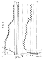
- Figure 1 shows an example of operation of a boiler with a device according to the invention.
- the upper curve 6 shows the temperature T at the boiler outlet as a function of time t
- a curve 8 called setpoint corresponds to the ideal water temperature in boiler outlet.
- This setpoint curve 8 is a function of the temperature outside the room heated by the corresponding heating. Of on either side of this setpoint curve 8, is in dotted lines a curve 10.
- the lower curve 16 of FIG. 1 represents the speed V of the motor driving the boiler fan as a function of time t.
- the time scale is identical for curves 6 and 16. Lines horizontal dotted lines, parallel to the time axis, correspond to four different gears of the engine speed V.
- a first speed X corresponds to the minimum speed below which we cannot go down. This speed corresponds to the minimum air flow necessary for correct operation of the boiler.
- a second speed Y corresponds at the boiler ignition speed.
- the speed Z corresponds to the speed pre-ventilation.
- the MAX speed corresponds to the maximum speed motor rotation.
- the boiler operates in two operating modes different: ignition mode and service mode.
- the modulator switches imperatively in ignition mode. During the course of this cycle, it ignores any change in state of the speed 4 electrical contact. ignition cycle is complete, the modulator switches to service mode.
- Ignition is controlled when the on contact 2 changes from the open position to the closed position.
- the modulator injects a weak current into the motor to block the fan wheel and eliminate any possible free rotation, due for example to the natural draft in the boiler.
- the modulator sends a control voltage to switch the motor to speed Z which corresponds to the pre-ventilation rate of the boiler and remains at this speed for a time T P.
- the modulator then commands the engine to switch to speed Y which corresponds to the ignition rate of the main burner of the boiler and remains in this state for the time T A.
- the boiler ignites during this time T A and the temperature of the water leaving the boiler begins to increase.
- the speed contact 4 When the speed contact 4 is closed, it tends to run the engine at its maximum speed while when in the open position, it tends to run the engine at minimum speed X.
- the speed switch 4 At the end of the ignition time T A , the speed switch 4 is closed. This is explained by the fact that the temperature T is still, at the end of ignition, lower than the set temperature given by curve 8.
- the speed contact 4 remains closed until the temperature T reaches the upper X curve.
- the speed contact 4 While the speed contact 4 is closed, the fan speed gradually increases according to a slope curve a.
- the motor speed increases until the MAX speed is reached or, as is the case in FIG. 1, until the temperature curve 6 reaches the upper dotted curve 10.
- the speed contact opens, commanding a reduction in the motor speed.
- This decrease in speed is also progressive and is also done with a ramp slope a.
- the decrease in fan speed results in a decrease in boiler power and the temperature at the boiler outlet decreases.
- the speed contact 4 remains in the open position until the temperature curve 6 reaches the lower dotted curve 10.
- the speed contact 4 then returns to the closed position.
- Figure 1 shows that thus by alternative openings and closings of the speed contact 4, the temperature curve 6 T follows, without deviating much, the setpoint curve 8.
- the speed of the motor driving the fan of the boiler then oscillates between minimum speed X and maximum speed MAX.
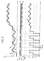
- Figure 2 is equivalent to Figure 1 but for a curve of different setpoint 8.
- the temperature outside temperature is relatively high and therefore the temperature at the outlet of boiler is relatively small.
- the temperature of the water leaving the boiler is such that the temperature curve 6 already reaches the upper dotted line 10 even before the end of the ignition cycle.
- the contact works 2 opens and the fan stops.
- several successive ignition cycles and boiler shutdowns are performed.
- the speed 4 contact closes and we find an operation similar to that described with reference to Figure 1.
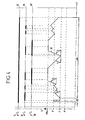
- DHW contact 18 Such a regulator with three electrical contacts is used for central heating also including a domestic hot water tank.
- Speed contact 4 and DHW contact 18 each order an increase or decrease the fan speed to move the fan to the maximum speed MAX or minimum X.
- the open or closed state of the contact speed 4 is controlled by a temperature sensor located on the circuit heating supplying the radiators while the open or closed state of the DHW 18 electrical contact is controlled by a probe placed in the circuit supplying the domestic hot water tank.
- the operating mode in FIG. 3 is identical to the operating mode in FIGS. 1 and 2. There is a period 22 of ignition of the boiler, then a period of 24 service followed by a stop of the boiler. We then again have a succession of modes 22, 24 service and boiler shutdown.
- the state of contact on step 2 is preponderant. So regardless of the open state or closed of speed 4 and DHW 18 contacts, when the on contact 2 is open, the boiler stops.
Abstract
Description
La présente invention concerne un dispositif de régulation pour une chaudière, notamment une chaudière de chauffage central.The present invention relates to a regulation device for a boiler, in particular a central heating boiler.
Un tel système de régulation a pour but de permettre de maintenir une température sensiblement constante dans les pièces chauffées à partir de la chaudière. Un système de chauffage classique comporte une chaudière, une vanne trois voies, deux pompes, ainsi que, bien entendu, les radiateurs alimentés à partir de la chaudière. La vanne trois voies permet de distribuer l'eau chaude produite au niveau de la chaudière en envoyant une quantité plus ou moins grande d'eau chaude vers les radiateurs. Cette vanne est commandée par un dispositif qui reçoit des informations de température (température extérieure, température dans les pièces, température de l'eau à la sortie de la chaudière, etc... ). Une pompe est nécessaire pour la circulation de l'eau vers les radiateurs et une autre pour la circulation de l'eau retournant directement vers la chaudière.The purpose of such a regulatory system is to maintain a substantially constant temperature in rooms heated from Boiler. A conventional heating system includes a boiler, a three-way valve, two pumps, as well as, of course, the radiators supplied from the boiler. The three-way valve distributes the hot water produced at the level of the boiler by sending a quantity more or less hot water to the radiators. This valve is controlled by a device that receives temperature information (outside temperature, room temperature, water temperature at boiler outlet, etc.). A pump is necessary for the circulation of water to the radiators and another for the return water circulation directly to the boiler.
Lorsque la température idéale est atteinte dans les pièces, on agit sur la chaudière pour éviter de dépasser une température prédéterminée. Plusieurs dispositifs existent. On peut par exemple avoir une chaudière qui est soit éteinte, soit qui fonctionne à 100% de sa capacité. On a alors un dispositif de régulation très simple mais on a une pollution relativement importante à chaque démarrage et à chaque arrêt de la chaudière. En outre, les variations de température au niveau de la chaudière sont importantes ce qui entraíne de fortes contraintes ayant pour conséquence une durée de vie de la chaudière limitée.When the ideal temperature is reached in the rooms, we act on the boiler to avoid exceeding a predetermined temperature. Several devices exist. We can for example have a boiler which is either switched off or operating at 100% of its capacity. We then have a device very simple regulation but there is a relatively significant pollution to each time the boiler is started and stopped. In addition, variations of temperature at the level of the boiler are important which results in high stresses resulting in a lifetime of the boiler limited.
Il existe également des chaudières dites chaudières "deux allures". Une telle chaudière peut fonctionner soit à 100% de sa capacité, soit avec une charge intermédiaire prédéterminée. On peut ainsi éviter de nombreux allumages et arrêts et de la chaudière. Toutefois, on a toujours des contraintes relativement élevées dues aux variations brutales de régime au niveau de la chaudière.There are also boilers called "two-stage" boilers. Such a boiler can operate either at 100% of its capacity, or with a predetermined intermediate load. We can thus avoid many ignitions and stops and of the boiler. However, we still have constraints relatively high due to sudden variations in engine speed boiler.
Le brevet américain US 5,894,988 décrit un système de chauffage auxiliaire pour des véhicules automobiles. Ce système comporte un dispositif de contrôle qui agit, pendant la phase d'allumage de la chaudière, sur la vitesse de rotation du ventilateur de la chaudière, afin d'améliorer la rapidité et la fiabilité de l'allumage du système de chauffage. Néanmoins, il n'y a pas de régulation de la puissance de chaudière au-delà de la période d'allumage. On a donc toujours des variations importantes de température dans la chaudière pendant le fonctionnement en mode service, donc un tel système, adapté sur une chaudière de chauffage central domestique, ne permet pas d'améliorer la durée de vie de la chaudière.American patent US 5,894,988 describes a heating system auxiliary for motor vehicles. This system includes a device control which acts, during the ignition phase of the boiler, on the speed of rotation of the boiler fan, in order to improve the speed and the reliability of the ignition of the heating system. However, there is no regulation of boiler power beyond the ignition period. We have therefore always significant variations in temperature in the boiler during operation in service mode, therefore such a system, adapted to a domestic central heating boiler, does not improve the lifetime of the boiler.
La présente invention a alors pour but de fournir les moyens permettant de moduler en puissance une chaudière à partir d'une régulation de chauffage standard pour chaudière deux allures et éviter ainsi les variations brutales de régime, au moment de l'allumage puis en mode service.The object of the present invention is therefore to provide the means for modulating the power of a boiler from a regulation of standard heating for two-stage boilers to avoid variations abrupt revs, upon ignition and then in service mode.
A cet effet, le dispositif qu'elle propose est un dispositif de régulation pour une chaudière, comportant un ventilateur entraíné par un moteur à vitesse variable, ce dispositif comportant un premier contact électrique et des moyens permettant de faire varier la vitesse de rotation du ventilateur, lors de la phase d'allumage de la chaudière, entre des positions d'arrêt, de marche selon une première allure qui correspond au débit de préventilation, ou de marche selon une deuxième allure qui correspond au débit d'allumage, le dispositif étant caractérisé en ce qu'il comporte un deuxième contact électrique prévu pour faire varier, après allumage de la chaudière et pendant le fonctionnement en mode service, la vitesse de rotation du ventilateur entre une première vitesse X minimale et une seconde vitesse MAX maximale, ces variations s'effectuant progressivement grâce aux moyens permettant de faire varier la vitesse du ventilateur lorsque le deuxième contact électrique est actionné.To this end, the device it offers is a regulation for a boiler, comprising a fan driven by a variable speed motor, this device comprising a first contact electric and means for varying the rotation speed of the fan, during the ignition phase of the boiler, between positions stop, walk at a first speed which corresponds to the flow of pre-ventilation, or walking at a second pace which corresponds to ignition rate, the device being characterized in that it comprises a second electrical contact provided to vary, after switching on the boiler and during operation in service mode, the rotation speed of the fan between a first minimum speed X and a second speed MAX maximum, these variations taking place gradually thanks to the means to vary the fan speed when the second contact electric is activated.
Ce dispositif de régulation permet de maintenir la température de l'eau en sortie de chaudière à une température très proche d'une température de consigne. Grâce à la variation progressive de la vitesse du ventilateur, et donc par conséquent de la puissance de la chaudière, les contraintes par variations rapides de températures sont évitées. De plus, un tel dispositif permet de limiter les allumages et arrêts de la chaudière. Ceux-ci se répètent uniquement dans les cas où les besoins en eau chaude sont faibles, ce qui ne représente qu'une faible part du fonctionnement d'une chaudière en général.This regulation device makes it possible to maintain the temperature of the water leaving the boiler at a temperature very close to a temperature setpoint. Thanks to the progressive variation of the fan speed, and therefore consequently of the power of the boiler, the constraints by rapid variations in temperature are avoided. In addition, such a device allows to limit the ignition and shutdown of the boiler. These are repeated only in cases where the hot water requirements are low, which does not represents only a small part of the operation of a boiler in general.
Dans un mode de réalisation préféré, les moyens prévus pour agir progressivement sur la vitesse du ventilateur comprennent un modulateur de fréquence à microprocesseur. Il est alors possible de mémoriser dans le microprocesseur un logiciel qui pilote la vitesse du ventilateur selon des données rentrées au préalable.In a preferred embodiment, the means provided for acting gradually on the fan speed include a modulator of microprocessor frequency. It is then possible to store in the microprocessor software that controls the fan speed according to data entered beforehand.
Ce modulateur de fréquence est avantageusement piloté à partir uniquement de l'état ouvert ou fermé des contacts électriques. Les températures extérieure et de l'eau produite par la chaudière sont utilisées quant à elles pour le pilotage des contacts électriques.This frequency modulator is advantageously controlled from only from the open or closed state of the electrical contacts. The outside temperatures and water produced by the boiler are used as for them for controlling the electrical contacts.
Dans le cas d'une installation comportant outre des radiateurs de chauffage, par exemple un ballon d'eau chaude sanitaire, le dispositif de régulation selon l'invention peut comporter un troisième contact électrique, prévu également pour faire passer le ventilateur de sa première à sa seconde allure ou inversement ; des moyens permettant de faire varier progressivement la vitesse du ventilateur lorsque le troisième contact électrique est actionné sont alors également prévus, et la variation de vitesse est différente selon qu'elle est commandée par l'un ou l'autre des contacts électriques. In the case of an installation comprising, in addition to radiators, heating, for example a domestic hot water tank, the regulation according to the invention may include a third electrical contact, also designed to switch the fan from its first to its second pace or vice versa; means for gradually varying the fan speed when the third electrical contact is activated are then also provided, and the speed variation is different according to that it is controlled by one or other of the electrical contacts.
La présente invention concerne également une chaudière pour chauffage central qui comporte un dispositif de régulation selon l'invention.The present invention also relates to a boiler for central heating which includes a regulating device according to the invention.
L'invention propose aussi un procédé de régulation pour une chaudière comportant un ventilateur entraíné par un moteur à vitesse variable, la chaudière étant munie d'un dispositif de régulation comportant un premier chaudière comportant un ventilateur entraíné par un moteur à vitesse variable, la chaudière étant munie d'un dispositif de régulation comportant un premier contact électrique qui commande la mise en marche et l'arrêt du ventilateur et un second contact électrique qui permet de choisir l'allure du ventilateur entre deux allures prédéterminées.The invention also provides a method of regulation for a boiler comprising a fan driven by a variable speed motor, the boiler being provided with a regulation device comprising a first boiler with a fan driven by a speed motor variable, the boiler being provided with a regulating device comprising a first electrical contact which controls the starting and stopping of the fan and a second electrical contact which allows you to choose the speed of the fan between two predetermined speeds.
D'après ce procédé :
- le premier contacteur est prioritaire sur le second, de telle sorte que si le premier contact est en position correspondant à l'arrêt du ventilateur, une action sur le second contact électrique est sans effet sur le ventilateur,
- lorsque le premier contact passe dans la position correspondant à la mise en marche du ventilateur, l'allumage de la chaudière est réalisé,
- lorsque le premier contact est en position de marche et que l'allumage de la chaudière est réalisé, et qu'on agit sur le second contact électrique, le ventilateur passe d'une première allure à une seconde allure progressivement selon une pente croissante ou décroissante prédéterminée.
- the first contactor has priority over the second, so that if the first contact is in the position corresponding to the fan stopping, an action on the second electrical contact has no effect on the fan,
- when the first contact goes into the position corresponding to the start-up of the fan, the boiler is switched on,
- when the first contact is in the on position and the boiler is switched on, and the second electrical contact is acted on, the fan changes from a first stage to a second stage gradually according to an increasing or decreasing slope predetermined.
Dans ce procédé, on peut prévoir que durant la phase d'allumage, le ventilateur est tout d'abord bloqué par injection d'un faible courant dans le moteur, puis que le ventilateur passe à une vitesse prédéterminée de préventilation pendant une durée prédéterminée avant de passer à une vitesse d'allumage pendant une durée également prédéterminée, une action sur le second contact étant sans effet sur le ventilateur durant toute cette phase d'allumage.In this process, it can be expected that during the phase the fan is first blocked by injecting a weak current in the motor, then the fan goes at a speed predetermined pre-ventilation for a predetermined period before switch to ignition speed for a period of time also predetermined, an action on the second contact having no effect on the fan during this entire ignition phase.
De toute façon, l'invention sera bien comprise à l'aide de la
description qui suit, en référence au dessin schématique annexé montrant
des courbes de fonctionnement d'un dispositif de régulation selon
l'invention.
Dans un premier mode de réalisation, le dispositif de régulation
est destiné à un chauffage central comportant une chaudière alimentant
plusieurs radiateurs. La chaudière est équipée d'une régulation de
chauffage standard pour chaudières "deux allures". Cette régulation
comporte alors deux contacts électriques. Un premier contact électrique 2,
appelé par la suite contact marche 2, commande la mise en marche et
l'arrêt de la chaudière. Lorsque ce contact marche 2 est fermé, la chaudière
est mise en route tandis que lorsque ce contact marche 2 est ouvert, la
chaudière s'arrête.In a first embodiment, the regulation device
is intended for central heating comprising a boiler supplying
several radiators. The boiler is equipped with a regulation of
standard heating for "two-stage" boilers. This regulation
then has two electrical contacts. A first
Un second contact électrique 4 est également prévu. Ce second contact 4, appelé par la suite contact vitesse 4, permet de choisir entre deux puissances de chauffage. En position fermée, la chaudière fonctionne au maximum de sa puissance tandis qu'en position ouverte, la chaudière fonctionne à une puissance intermédiaire.A second electrical contact 4 is also provided. This second contact 4, subsequently called speed contact 4, allows you to choose between two heating powers. In closed position, the boiler works at full power while in the open position, the boiler operates at an intermediate power.
La puissance de la chaudière module par variation du débit d'air
envoyé dans le brûleur. Un ventilateur envoie cet air dans le brûleur. Il est
équipé d'un moteur à vitesse variable commandé par la régulation de
chauffage. Dans le dispositif selon l'invention, un modulateur de fréquence
à microprocesseur est disposé entre la régulation de chauffage standard
"deux allures" et le moteur à vitesse variable. Un logiciel spécifique
mémorisé dans le microprocesseur permet de piloter la chaudière à partir de
l'état ouvert ou fermé des deux contacts électriques 2, 4 du régulateur de
chauffage.The power of the boiler modulates by variation of the air flow
sent to the burner. A fan sends this air to the burner. It is
equipped with a variable speed motor controlled by the regulation of
heater. In the device according to the invention, a frequency modulator
with microprocessor is placed between the standard heating control
"two gears" and the variable speed motor. Specific software
stored in the microprocessor allows the boiler to be controlled from
the open or closed state of the two
Dans un dispositif de l'art antérieur, lorsque le contact vitesse 4 est ouvert ou fermé, la vitesse du ventilateur, à l'inertie du moteur et du ventilateur près, change immédiatement de régime.In a device of the prior art, when the speed contact 4 is open or closed, the fan speed, at the inertia of the motor and fan close, immediately changes speed.
Selon l'invention, cette variation de régime se fait
progressivement. La figure 1 montre un exemple de fonctionnement d'une
chaudière avec un dispositif selon l'invention. La courbe 6 supérieure
montre la température T en sortie de chaudière en fonction du temps t, une
courbe 8 appelée consigne, correspond à la température idéale de l'eau en
sortie de chaudière. Cette courbe de consigne 8 est fonction de la
température extérieure au local chauffé par le chauffage correspondant. De
part et d'autre de cette courbe de consigne 8, se trouve en traits pointillés
une courbe 10.According to the invention, this variation in speed is done
gradually. Figure 1 shows an example of operation of a
boiler with a device according to the invention. The
Au milieu de la figure 1, est indiqué le positionnement des
contacts électriques 2 et 4. Sur la ligne 12, la zone en noir correspond à la
fermeture du contact marche 2 tandis que la zone blanche correspond à
l'ouverture de ce contact 2. Il en va de même sur la ligne 14 pour le
contact vitesse 4.In the middle of Figure 1, the positioning of the
La courbe 16 inférieure de la figure 1 représente la vitesse V du
moteur entraínant le ventilateur de la chaudière en fonction du temps t.
L'échelle de temps est identique pour les courbes 6 et 16. Des lignes
horizontales pointillées, parallèles à l'axe des temps, correspondent à
quatre allures différentes de la vitesse V du moteur. Une première vitesse X
correspond à la vitesse minimale en dessous de laquelle on ne peut pas
descendre. Cette vitesse correspond au flux d'air minimal nécessaire pour
un bon fonctionnement de la chaudière. Une seconde vitesse Y correspond
à la vitesse d'allumage de la chaudière. La vitesse Z correspond à la vitesse
de préventilation. Enfin, la vitesse MAX correspond à la vitesse maximale
de rotation du moteur.The
La chaudière fonctionne selon deux modes de fonctionnement différents : le mode allumage et le mode service.The boiler operates in two operating modes different: ignition mode and service mode.
A chaque démarrage de la chaudière, le modulateur passe impérativement en mode allumage. Pendant le déroulement de ce cycle, il ignore tout changement d'état du contact électrique vitesse 4. Lorsque le cycle d'allumage est terminé, le modulateur passe en mode service.Each time the boiler is started, the modulator switches imperatively in ignition mode. During the course of this cycle, it ignores any change in state of the speed 4 electrical contact. ignition cycle is complete, the modulator switches to service mode.
L'allumage est commandé lorsque le contact marche 2 passe de
la position ouverte à la position fermée. Pendant un temps TO le modulateur
injecte un courant faible dans le moteur pour bloquer la roue du ventilateur
et supprimer toute rotation libre éventuelle, due par exemple au tirage
naturel dans la chaudière. Puis le modulateur envoie une tension de
commande pour faire passer le moteur à la vitesse Z qui correspond au
débit de préventilation de la chaudière et reste à cette vitesse pendant un
temps TP . Le modulateur commande ensuite le moteur de passer à la
vitesse Y qui correspond au débit d'allumage du brûleur principal de la
chaudière et reste dans cet état pendant le temps TA . La chaudière
s'allume durant ce temps TA et la température de l'eau en sortie de
chaudière commence à augmenter.Ignition is controlled when the on
A la fin du temps TA , le cycle d'allumage est terminé. La durée totale de ce cycle et les différents temps pris en compte sont synchronisés avec un cycle effectué par un coffret de contrôle et de sécurité de la chaudière.At the end of time T A , the ignition cycle is finished. The total duration of this cycle and the different times taken into account are synchronized with a cycle carried out by a boiler control and safety box.
Lorsque le contact vitesse 4 est fermé, il tend à faire tourner le
moteur à sa vitesse maximale tandis que lorsqu'il est en position ouverte, il
tend à faire tourner le moteur à la vitesse X minimale. A la fin du temps TA
d'allumage, le contacteur de vitesse 4 est fermé. Ceci s'explique par le fait
que la température T est encore, à la fin de l'allumage, inférieure à la
température de consigne donnée par la courbe 8. Le contact vitesse 4 reste
fermé jusqu'à ce que la température T atteigne la courbe X supérieure.
Pendant que le contact vitesse 4 est fermé, la vitesse du ventilateur
augmente progressivement selon une courbe de pente a. La vitesse du
moteur augmente jusqu'à ce que la vitesse MAX soit atteinte ou bien,
comme c'est le cas sur la figure 1, jusqu'à ce que la courbe de température
6 atteigne la courbe en pointillés supérieure 10. A ce moment, le contact
vitesse s'ouvre commandant alors une diminution de la vitesse du moteur.
Cette diminution de vitesse est également progressive et se fait également
avec une pente de rampe a. La diminution de la vitesse du ventilateur a
pour conséquence la diminution de puissance de la chaudière et la
température en sortie de chaudière diminue. Le contact vitesse 4 reste en
position ouverte jusqu'à ce que la courbe de température 6 atteigne la
courbe en pointillés inférieure 10. Le contact vitesse 4 se met alors à
nouveau en position de fermeture. La figure 1 montre qu'ainsi par
ouvertures et fermetures alternatives du contact vitesse 4, la courbe 6 de
température T suit, sans s'en éloigner beaucoup, la courbe de consigne 8.
La vitesse du moteur entraínant le ventilateur de la chaudière oscille alors
entre la vitesse minimale X et la vitesse maximale MAX.When the speed contact 4 is closed, it tends to run the engine at its maximum speed while when in the open position, it tends to run the engine at minimum speed X. At the end of the ignition time T A , the speed switch 4 is closed. This is explained by the fact that the temperature T is still, at the end of ignition, lower than the set temperature given by curve 8. The speed contact 4 remains closed until the temperature T reaches the upper X curve. While the speed contact 4 is closed, the fan speed gradually increases according to a slope curve a. The motor speed increases until the MAX speed is reached or, as is the case in FIG. 1, until the
La figure 2 est équivalente à la figure 1 mais pour une courbe de
consigne 8 différente. On peut supposer ici qu'au départ, la température
extérieure est relativement élevée et de ce fait, la température en sortie de
chaudière est relativement faible. Comme on peut le voir, durant le cycle
d'allumage, la température de l'eau en sortie de chaudière est telle que la
courbe de température 6 atteint déjà la ligne en pointillés supérieure 10
avant même la fin du cycle d'allumage. A ce moment, le contact marche 2
s'ouvre et le ventilateur s'arrête. Pour maintenir alors la température de
consigne en sortie de chaudière, plusieurs cycles successifs d'allumage et
d'arrêt de la chaudière sont réalisés. Lorsque la température extérieure
diminue, et que donc la température en sortie de chaudière doit être plus
élevée, le contact vitesse 4 se ferme et on retrouve un fonctionnement
analogue à celui décrit en référence à la figure 1. Figure 2 is equivalent to Figure 1 but for a curve of
different setpoint 8. We can assume here that at the start, the temperature
outside temperature is relatively high and therefore the temperature at the outlet of
boiler is relatively small. As we can see, during the cycle
the temperature of the water leaving the boiler is such that the
Sur les figures 3 et 4 on retrouve en plus du contact marche 2
et du contact vitesse 4 un contact appelé contact ecs 18. Un tel régulateur
comportant trois contacts électriques est utilisé pour un chauffage central
comprenant également un ballon d'eau chaude sanitaire. Le contact vitesse
4 et le contact ecs 18 commandent chacun une augmentation ou
diminution de la vitesse du ventilateur pour faire passer celui-ci vers la
vitesse maximale MAX ou minimale X. L'état ouvert ou fermé du contact
vitesse 4 est commandé par une sonde de température située sur le circuit
de chauffage alimentant les radiateurs tandis que l'état ouvert ou fermé du
contact électrique ecs 18 est commandé par une sonde placée dans le
circuit alimentant le ballon d'eau chaude sanitaire.In Figures 3 and 4 we find in addition to the on
Sur la figure 3, la température en sortie de chaudière n'a pas été
représentée. On retrouve les lignes 12 et 14 montrant l'état ouvert et
fermé des contacts électriques 2 et 4 ainsi qu'une ligne 20 pour montrer
l'état ouvert ou fermé du contact ecs 18. Sur la figure 3, le contact ecs est
toujours en position ouverte. Sur la figure 4, la ligne 20 indique les périodes
durant lesquelles le contact ecs 18 est ouvert par un trait fort noir.In Figure 3, the temperature at the boiler outlet has not been
represented. We find
Le mode de fonctionnement sur la figure 3 est identique au
mode de fonctionnement sur les figures 1 et 2. On trouve une période 22
d'allumage de la chaudière, puis une période 24 de service suivie d'un arrêt
de la chaudière. On a alors de nouveau une succession de modes
d'allumage 22, de service 24 et d'arrêt de la chaudière.The operating mode in FIG. 3 is identical to the
operating mode in FIGS. 1 and 2. There is a
Sur la figure 4, on voit l'influence du contact électrique ecs 18.
Lorsque ce contact ecs 18 est fermé, la vitesse du moteur, et donc du
ventilateur, augmente. Cette augmentation de vitesse se fait
progressivement mais la rampe de la pente d'augmentation de vitesse est
d'une valeur b. Cette valeur b est supérieure à la valeur a de la rampe
d'augmentation de vitesse lorsque le contact vitesse 4 se ferme. Ceci
permet d'avoir une montée en température plus rapide pour l'eau chaude
sanitaire. Par contre, lorsque le contact électrique ecs 18 s'ouvre, la
variation de vitesse au niveau du ventilateur et de son moteur se fait selon
une rampe de pente a.In Figure 4, we can see the influence of the DHW
En résumé, on retrouve sur les figures 3 et 4 également un
mode d'allumage et un mode de service. Pendant le déroulement du cycle
d'allumage, le changement d'état des contacts électriques vitesse 4 et ecs
18 est ignoré. Par contre, si le contacteur marche 2 s'ouvre, le modulateur
arrête la chaudière et reste en attente d'un nouvel ordre de démarrage.In summary, we find in Figures 3 and 4 also a
ignition mode and a service mode. During the cycle
ignition, change of state of speed 4 and DHW
En mode service, lorsque les contacts électriques vitesse 4 et
ecs 18 sont ouverts, il n'y a pas besoin d'eau chaude sanitaire ni d'eau
chaude pour le chauffage. Le modulateur fait alors diminuer la vitesse du
ventilateur avec une rampe a. Si la vitesse arrive à la vitesse minimale
autorisée X, cette vitesse reste calée à cette valeur jusqu'à obtenir un
nouvel ordre du régulateur.In service mode, when the electrical contacts speed 4 and
Lorsque le contact électrique vitesse 4 est fermé et le contact
électrique ecs 18 est ouvert, il y a un besoin en eau chaude pour le
chauffage mais pas de besoin en eau chaude sanitaire. Le modulateur fait
alors progressivement augmenter la vitesse du ventilateur avec une rampe
a. Si on arrive à la vitesse MAX, cette vitesse est conservée jusqu'à nouvel
ordre du régulateur.When the speed 4 electrical contact is closed and the contact
Lorsque les deux contacts électriques vitesse 4 et ecs 18 sont
fermés il y a à la fois un besoin en eau chaude pour le chauffage et un
besoin en eau chaude sanitaire. La production d'eau chaude sanitaire étant
prioritaire, c'est ce contact qui définit le comportement du modulateur.
Celui-ci va faire augmenter progressivement la vitesse du ventilateur avec
une rampe b jusqu'à ce que la vitesse MAX soit atteinte. Le ventilateur
reste calé sur cette vitesse MAX jusqu'à ce que le contact électrique ecs
18 s'ouvre.When the two electrical contacts speed 4 and
Enfin, dans le dernier cas de figure, dans lequel le contact
électrique vitesse 4 est ouvert et le contact ecs 18 est fermé, il n'y a pas
de besoin en eau chaude pour le chauffage mais il y a un besoin en eau
chaude sanitaire. Le modulateur fait alors progressivement augmenter la
vitesse du ventilateur avec une rampe b jusqu'à la vitesse maximale MAX
qui reste calée à cette valeur jusqu'à ce que le contact électrique ecs 18
s'ouvre.Finally, in the last case, in which the contact
electric speed 4 is open and
Durant tout le mode de fonctionnement service, l'état du
contact marche 2 est prépondérant. Ainsi, quel que soit l'état ouvert ou
fermé des contacts vitesse 4 et ecs 18, lorsque le contact marche 2 est
ouvert, la chaudière s'arrête.Throughout the service operating mode, the state of
contact on
Tous les paramètres de fonctionnement, vitesses X, Y, Z, temps TO, TP, TA et rampes a et b, sont réglables. Ils sont programmés dans le logiciel mémorisé dans le microprocesseur du modulateur de fréquence. Ces variables peuvent être ajustées également par des dispositifs de réglage accessibles sur le modulateur. Ces variables sont bien entendu dépendantes du type de chaudière et des besoins.All operating parameters, speeds X, Y, Z, time T O , T P , T A and ramps a and b, are adjustable. They are programmed in the software stored in the microprocessor of the frequency modulator. These variables can also be adjusted by adjustment devices accessible on the modulator. These variables are of course dependent on the type of boiler and the needs.
Comme montré ci-dessus on peut donc avoir avec une régulation de chauffage standard pour chaudière "deux allures" une chaudière modulante qui permet de moduler le fonctionnement de la chaudière en restant proche d'une courbe de consigne donnée.As shown above we can therefore have with a regulation standard heating for "two-stage" boiler one modulating boiler which modulates the operation of the boiler by staying close of a given setpoint curve.
L'utilisation d'un tel dispositif de régulation dans un système de chauffage central permet de n'utiliser qu'une seule pompe à la place des deux pompes habituellement utilisées en combinaison avec une vanne pilotée trois voies. Le surcoût engendré par la mise en place du modulateur de fréquence à microprocesseur intégré est nettement inférieur au coût de la pompe et de la vanne pilotée trois voies que l'on peut économiser. On obtient donc à peu de frais un système de chauffage central à régulation modulante.The use of such a regulating device in a central heating allows only one pump to be used instead of two pumps usually used in combination with a three-way valve tract. The additional cost generated by the installation of the frequency modulator integrated microprocessor is significantly lower than the cost of the pump and three-way pilot valve that can be saved. So we get a little costs a modulating central heating system.
Claims (7)
- Regulating device for a boiler having a fan driven by a variable-speed motor, the said device having a first electrical contact (2) and means which make it possible to vary the rotational speed of the fan, in the firing phase of the boiler, between positions for stopping, running at a first speed which corresponds to the flow of preventilation air, or running at a second speed which corresponds to the flow of firing air, the device being characterised in that it has a second electrical contact (4) which is designed to vary, after firing of the boiler and during operation in the service mode, the rotational speed of the fan between a first, minimum speed (X) and a second, maximum speed (MAX), the said variations taking place progressively owing to the means which make it possible to vary the speed of the fan when the second electrical contact (4) is activated.
- Regulating device according to claim 1, characterised in that the means which are designed to act progressively on the speed of the fan comprise a microprocessor-type frequency-modulator.
- Regulating device according to claim 2, characterised in that the frequency-modulator is guided solely from the open or closed state of the electrical contacts (2, 4, 18).
- Regulating device according to one of claims 1 to 3, characterised in that it has a third electrical contact (18) which is also designed to cause the fan to pass from its first speed (X) to its second speed (MAX) or vice versa, in that means are provided which make it possible to progressively vary the speed of the fan when the third electrical contact (18) is activated, and in that the variation in speed is different according to whether it is controlled by one or other of the electrical contacts.
- Boiler for central heating, characterised in that it has a regulating device according to one of claims 1 to 4.
- Method of regulation for a boiler having a fan driven by a variable-speed motor, the said boiler being equipped with a regulating device having a first electrical contact (2) and means which make it possible to vary the rotational speed of the fan, in the firing phase of the boiler, between positions for stopping, running at a first speed which corresponds to the preventilation flow, or running at a second speed which corresponds to the firing flow, in which method the firing of the boiler is carried out when the first contact (2) passes into the position corresponding to the starting-up of the fan, characterised in that the regulating device has a second electrical contact (4, 18) which make it possible, after the firing phase and when the boiler is in service mode, to choose the speed of the fan between two predetermined speeds (X, MAX), and in that :the first contact (2) has priority over the second (4, 18) in such a way that, if the first contact (2) is in a position corresponding to the stopping of the fan, action on the second contact (4, 18) has no effect on the said fan,when the first contact (2) is in the running position and the firing of the boiler has been carried out, and when the second electrical contact is acted upon with the boiler in the service mode, the fan passes from a first speed (X) to a second speed (MAX) progressively along a predetermined rising or falling gradient (a, b).
- Method according to claim 6, characterised in that, during the firing phase, the fan is first of all brought to a standstill by the injection of a low current into the motor, then the said fan passes to a predetermined preventilation speed (Z) for a predetermined duration (TP) before passing to a firing speed (Y) for a duration (TA) which is likewise predetermined, action on the second contact (4, 18) having no effect on the fan during the whole of the said firing phase.
Applications Claiming Priority (2)
| Application Number | Priority Date | Filing Date | Title |
|---|---|---|---|
| FR9905813 | 1999-05-04 | ||
| FR9905813A FR2793308B1 (en) | 1999-05-04 | 1999-05-04 | REGULATING DEVICE FOR BOILER |
Publications (2)
| Publication Number | Publication Date |
|---|---|
| EP1050714A1 EP1050714A1 (en) | 2000-11-08 |
| EP1050714B1 true EP1050714B1 (en) | 2002-12-18 |
Family
ID=9545321
Family Applications (1)
| Application Number | Title | Priority Date | Filing Date |
|---|---|---|---|
| EP00420086A Revoked EP1050714B1 (en) | 1999-05-04 | 2000-04-27 | Boiler controlling device |
Country Status (4)
| Country | Link |
|---|---|
| EP (1) | EP1050714B1 (en) |
| AT (1) | ATE230095T1 (en) |
| DE (1) | DE60001011T2 (en) |
| FR (1) | FR2793308B1 (en) |
Family Cites Families (2)
| Publication number | Priority date | Publication date | Assignee | Title |
|---|---|---|---|---|
| DE19507556B4 (en) * | 1994-10-20 | 2004-12-30 | J. Eberspächer GmbH & Co. KG | Method for starting a burner for a vehicle heater or a particle filter regenerator |
| JPH10213320A (en) * | 1997-01-28 | 1998-08-11 | Kawasaki Thermal Eng Co Ltd | Combustion control method for three position control boiler |
-
1999
- 1999-05-04 FR FR9905813A patent/FR2793308B1/en not_active Expired - Fee Related
-
2000
- 2000-04-27 AT AT00420086T patent/ATE230095T1/en not_active IP Right Cessation
- 2000-04-27 EP EP00420086A patent/EP1050714B1/en not_active Revoked
- 2000-04-27 DE DE60001011T patent/DE60001011T2/en not_active Expired - Fee Related
Also Published As
| Publication number | Publication date |
|---|---|
| ATE230095T1 (en) | 2003-01-15 |
| FR2793308A1 (en) | 2000-11-10 |
| DE60001011D1 (en) | 2003-01-30 |
| FR2793308B1 (en) | 2001-07-20 |
| DE60001011T2 (en) | 2003-09-04 |
| EP1050714A1 (en) | 2000-11-08 |
Similar Documents
| Publication | Publication Date | Title |
|---|---|---|
| FR2554165A1 (en) | METHOD FOR CONTROLLING THE TEMPERATURE OF THE COOLING LIQUID OF AN INTERNAL COMBUSTION ENGINE AND DEVICE FOR IMPLEMENTING IT | |
| FR2742809A1 (en) | METHOD AND DEVICE FOR CONTROLLING AN INTERNAL COMBUSTION ENGINE | |
| WO1984000578A1 (en) | Cooling device for an internal combustion engine | |
| FR2843168A1 (en) | Heating and cooling system for vehicle engine uses heat accumulator with electro-valve control to assist with engine warm-up | |
| FR2797309A1 (en) | SYSTEM AND CONTROL PROCEDURE FOR A VARIABLE PRESSURE FUEL SUPPLY MODULE | |
| FR2809059A1 (en) | METHOD AND DEVICE FOR CONTROLLING A POWER UNIT OF A MOTOR VEHICLE | |
| EP1041277B1 (en) | Vehicle starter control device for preventing wear | |
| EP1050714B1 (en) | Boiler controlling device | |
| FR2767866A1 (en) | METHOD AND DEVICE FOR CONTROLLING A USER | |
| FR2847734A1 (en) | Overload failure prevention method for IC engine, involves reducing response rate of starter/alternator when monitored response rate exceeds predetermined threshold value | |
| FR2549205A1 (en) | Regulating heating installation taking into account external temp. | |
| EP1396002B1 (en) | Power supply method for electrical equipment | |
| EP1041278B1 (en) | Vehicle starter control device to produce less starter wear | |
| FR2759108A1 (en) | Low loss emergency power supply for vehicle door lock | |
| FR2520807A1 (en) | CONTROL ARRANGEMENT FOR INTERNAL COMBUSTION ENGINE | |
| EP1041276B1 (en) | Vehicle starter with reduced wear | |
| FR2706228A1 (en) | Method and device for regulating the power supply of an asynchronous electric motor | |
| EP2817865B1 (en) | Method for managing the electrical energy of an electrical architecture of a motor vehicle, and motor vehicle implementing such a method | |
| FR2808305A1 (en) | Method and equipment for cooling vehicle heat engine, comprises calculator which receives engine load and entry and exit temperatures and controls coolant pump, radiator fan and radiator bypass valve | |
| EP0826934B1 (en) | Method for controlling the charging and decharging of electric storage heaters | |
| FR2661237A1 (en) | Temperature regulating method and device for heating installation | |
| FR2551567A1 (en) | INTERFACE FOR CONTROLLING AND REGULATING TEMPERATURE AND HYGROMETRY | |
| FR2711584A3 (en) | Method and device for controlling the compressor of an air-conditioning (climate control) installation in a motor vehicle | |
| FR2521696A1 (en) | Hot water central heating installation - uses outlet water temp. sensor and microprocessor to control operation of boiler and heat pump for optimum usage | |
| FR2555297A1 (en) | ORDERING THE AIR COMPARTMENT OF A TWO-STAGE BURNER, WITH FIELD OR GAS |
Legal Events
| Date | Code | Title | Description |
|---|---|---|---|
| PUAI | Public reference made under article 153(3) epc to a published international application that has entered the european phase |
Free format text: ORIGINAL CODE: 0009012 |
|
| AK | Designated contracting states |
Kind code of ref document: A1 Designated state(s): AT BE CH CY DE DK ES FI FR GB GR IE IT LI LU MC NL PT SE |
|
| AX | Request for extension of the european patent |
Free format text: AL;LT;LV;MK;RO;SI |
|
| 17P | Request for examination filed |
Effective date: 20010417 |
|
| AKX | Designation fees paid |
Free format text: AT BE CH CY DE DK ES FI FR GB GR IE IT LI LU MC NL PT SE |
|
| 17Q | First examination report despatched |
Effective date: 20010724 |
|
| GRAG | Despatch of communication of intention to grant |
Free format text: ORIGINAL CODE: EPIDOS AGRA |
|
| GRAG | Despatch of communication of intention to grant |
Free format text: ORIGINAL CODE: EPIDOS AGRA |
|
| GRAH | Despatch of communication of intention to grant a patent |
Free format text: ORIGINAL CODE: EPIDOS IGRA |
|
| GRAH | Despatch of communication of intention to grant a patent |
Free format text: ORIGINAL CODE: EPIDOS IGRA |
|
| GRAA | (expected) grant |
Free format text: ORIGINAL CODE: 0009210 |
|
| AK | Designated contracting states |
Kind code of ref document: B1 Designated state(s): AT BE CH CY DE DK ES FI FR GB GR IE IT LI LU MC NL PT SE |
|
| PG25 | Lapsed in a contracting state [announced via postgrant information from national office to epo] |
Ref country code: NL Free format text: LAPSE BECAUSE OF FAILURE TO SUBMIT A TRANSLATION OF THE DESCRIPTION OR TO PAY THE FEE WITHIN THE PRESCRIBED TIME-LIMIT Effective date: 20021218 Ref country code: IE Free format text: LAPSE BECAUSE OF FAILURE TO SUBMIT A TRANSLATION OF THE DESCRIPTION OR TO PAY THE FEE WITHIN THE PRESCRIBED TIME-LIMIT Effective date: 20021218 Ref country code: GR Free format text: LAPSE BECAUSE OF FAILURE TO SUBMIT A TRANSLATION OF THE DESCRIPTION OR TO PAY THE FEE WITHIN THE PRESCRIBED TIME-LIMIT Effective date: 20021218 Ref country code: GB Free format text: LAPSE BECAUSE OF FAILURE TO SUBMIT A TRANSLATION OF THE DESCRIPTION OR TO PAY THE FEE WITHIN THE PRESCRIBED TIME-LIMIT Effective date: 20021218 Ref country code: FI Free format text: LAPSE BECAUSE OF FAILURE TO SUBMIT A TRANSLATION OF THE DESCRIPTION OR TO PAY THE FEE WITHIN THE PRESCRIBED TIME-LIMIT Effective date: 20021218 Ref country code: AT Free format text: LAPSE BECAUSE OF FAILURE TO SUBMIT A TRANSLATION OF THE DESCRIPTION OR TO PAY THE FEE WITHIN THE PRESCRIBED TIME-LIMIT Effective date: 20021218 |
|
| REF | Corresponds to: |
Ref document number: 230095 Country of ref document: AT Date of ref document: 20030115 Kind code of ref document: T |
|
| REG | Reference to a national code |
Ref country code: GB Ref legal event code: FG4D Free format text: NOT ENGLISH |
|
| REG | Reference to a national code |
Ref country code: CH Ref legal event code: EP |
|
| REG | Reference to a national code |
Ref country code: CH Ref legal event code: NV Representative=s name: MICHELI & CIE INGENIEURS-CONSEILS |
|
| REG | Reference to a national code |
Ref country code: IE Ref legal event code: FG4D Free format text: FRENCH |
|
| REF | Corresponds to: |
Ref document number: 60001011 Country of ref document: DE Date of ref document: 20030130 Kind code of ref document: P Ref document number: 60001011 Country of ref document: DE Date of ref document: 20030130 |
|
| PG25 | Lapsed in a contracting state [announced via postgrant information from national office to epo] |
Ref country code: SE Free format text: LAPSE BECAUSE OF FAILURE TO SUBMIT A TRANSLATION OF THE DESCRIPTION OR TO PAY THE FEE WITHIN THE PRESCRIBED TIME-LIMIT Effective date: 20030318 Ref country code: PT Free format text: LAPSE BECAUSE OF FAILURE TO SUBMIT A TRANSLATION OF THE DESCRIPTION OR TO PAY THE FEE WITHIN THE PRESCRIBED TIME-LIMIT Effective date: 20030318 Ref country code: DK Free format text: LAPSE BECAUSE OF FAILURE TO SUBMIT A TRANSLATION OF THE DESCRIPTION OR TO PAY THE FEE WITHIN THE PRESCRIBED TIME-LIMIT Effective date: 20030318 |
|
| PGFP | Annual fee paid to national office [announced via postgrant information from national office to epo] |
Ref country code: FR Payment date: 20030329 Year of fee payment: 4 |
|
| PGFP | Annual fee paid to national office [announced via postgrant information from national office to epo] |
Ref country code: DE Payment date: 20030403 Year of fee payment: 4 |
|
| PGFP | Annual fee paid to national office [announced via postgrant information from national office to epo] |
Ref country code: BE Payment date: 20030423 Year of fee payment: 4 |
|
| PG25 | Lapsed in a contracting state [announced via postgrant information from national office to epo] |
Ref country code: LU Free format text: LAPSE BECAUSE OF NON-PAYMENT OF DUE FEES Effective date: 20030427 Ref country code: CY Free format text: LAPSE BECAUSE OF FAILURE TO SUBMIT A TRANSLATION OF THE DESCRIPTION OR TO PAY THE FEE WITHIN THE PRESCRIBED TIME-LIMIT Effective date: 20030427 |
|
| PG25 | Lapsed in a contracting state [announced via postgrant information from national office to epo] |
Ref country code: MC Free format text: LAPSE BECAUSE OF NON-PAYMENT OF DUE FEES Effective date: 20030430 |
|
| GBV | Gb: ep patent (uk) treated as always having been void in accordance with gb section 77(7)/1977 [no translation filed] |
Effective date: 20021218 |
|
| PG25 | Lapsed in a contracting state [announced via postgrant information from national office to epo] |
Ref country code: ES Free format text: LAPSE BECAUSE OF FAILURE TO SUBMIT A TRANSLATION OF THE DESCRIPTION OR TO PAY THE FEE WITHIN THE PRESCRIBED TIME-LIMIT Effective date: 20030627 |
|
| REG | Reference to a national code |
Ref country code: IE Ref legal event code: FD4D Ref document number: 1050714E Country of ref document: IE |
|
| PLBQ | Unpublished change to opponent data |
Free format text: ORIGINAL CODE: EPIDOS OPPO |
|
| PLBI | Opposition filed |
Free format text: ORIGINAL CODE: 0009260 |
|
| PLAX | Notice of opposition and request to file observation + time limit sent |
Free format text: ORIGINAL CODE: EPIDOSNOBS2 |
|
| 26 | Opposition filed |
Opponent name: VAILLANT GMBH Effective date: 20030916 |
|
| PG25 | Lapsed in a contracting state [announced via postgrant information from national office to epo] |
Ref country code: LI Free format text: LAPSE BECAUSE OF NON-PAYMENT OF DUE FEES Effective date: 20040430 Ref country code: CH Free format text: LAPSE BECAUSE OF NON-PAYMENT OF DUE FEES Effective date: 20040430 Ref country code: BE Free format text: LAPSE BECAUSE OF NON-PAYMENT OF DUE FEES Effective date: 20040430 |
|
| PLAX | Notice of opposition and request to file observation + time limit sent |
Free format text: ORIGINAL CODE: EPIDOSNOBS2 |
|
| BERE | Be: lapsed |
Owner name: *GUILLOT INDUSTRIE Effective date: 20040430 |
|
| PG25 | Lapsed in a contracting state [announced via postgrant information from national office to epo] |
Ref country code: DE Free format text: LAPSE BECAUSE OF NON-PAYMENT OF DUE FEES Effective date: 20041103 |
|
| REG | Reference to a national code |
Ref country code: CH Ref legal event code: PL |
|
| PG25 | Lapsed in a contracting state [announced via postgrant information from national office to epo] |
Ref country code: FR Free format text: LAPSE BECAUSE OF NON-PAYMENT OF DUE FEES Effective date: 20041231 |
|
| REG | Reference to a national code |
Ref country code: FR Ref legal event code: ST |
|
| PG25 | Lapsed in a contracting state [announced via postgrant information from national office to epo] |
Ref country code: IT Free format text: LAPSE BECAUSE OF NON-PAYMENT OF DUE FEES Effective date: 20050427 |
|
| RDAF | Communication despatched that patent is revoked |
Free format text: ORIGINAL CODE: EPIDOSNREV1 |
|
| RDAG | Patent revoked |
Free format text: ORIGINAL CODE: 0009271 |
|
| STAA | Information on the status of an ep patent application or granted ep patent |
Free format text: STATUS: PATENT REVOKED |
|
| 27W | Patent revoked |
Effective date: 20060629 |