EP1050644B1 - Vehicle door handle - Google Patents
Vehicle door handle Download PDFInfo
- Publication number
- EP1050644B1 EP1050644B1 EP00109651A EP00109651A EP1050644B1 EP 1050644 B1 EP1050644 B1 EP 1050644B1 EP 00109651 A EP00109651 A EP 00109651A EP 00109651 A EP00109651 A EP 00109651A EP 1050644 B1 EP1050644 B1 EP 1050644B1
- Authority
- EP
- European Patent Office
- Prior art keywords
- lever
- mass
- handle assembly
- axis
- door
- Prior art date
- Legal status (The legal status is an assumption and is not a legal conclusion. Google has not performed a legal analysis and makes no representation as to the accuracy of the status listed.)
- Expired - Lifetime
Links
- 230000005540 biological transmission Effects 0.000 claims description 20
- 230000000284 resting effect Effects 0.000 claims description 5
- 230000003068 static effect Effects 0.000 claims description 2
- 239000003795 chemical substances by application Substances 0.000 description 1
- 239000000428 dust Substances 0.000 description 1
- 230000000694 effects Effects 0.000 description 1
- 230000036316 preload Effects 0.000 description 1
- XLYOFNOQVPJJNP-UHFFFAOYSA-N water Substances O XLYOFNOQVPJJNP-UHFFFAOYSA-N 0.000 description 1
Images
Classifications
-
- E—FIXED CONSTRUCTIONS
- E05—LOCKS; KEYS; WINDOW OR DOOR FITTINGS; SAFES
- E05B—LOCKS; ACCESSORIES THEREFOR; HANDCUFFS
- E05B77/00—Vehicle locks characterised by special functions or purposes
- E05B77/02—Vehicle locks characterised by special functions or purposes for accident situations
- E05B77/04—Preventing unwanted lock actuation, e.g. unlatching, at the moment of collision
- E05B77/06—Preventing unwanted lock actuation, e.g. unlatching, at the moment of collision by means of inertial forces
-
- E—FIXED CONSTRUCTIONS
- E05—LOCKS; KEYS; WINDOW OR DOOR FITTINGS; SAFES
- E05B—LOCKS; ACCESSORIES THEREFOR; HANDCUFFS
- E05B85/00—Details of vehicle locks not provided for in groups E05B77/00 - E05B83/00
- E05B85/10—Handles
- E05B85/14—Handles pivoted about an axis parallel to the wing
- E05B85/16—Handles pivoted about an axis parallel to the wing a longitudinal grip part being pivoted at one end about an axis perpendicular to the longitudinal axis of the grip part
Definitions
- the present invention relates to a vehicle door handle.
- Handles comprising a user-activated control lever rotated between a rest position maintained by a preloaded return spring, and a work position to open a lock on the door by means of a transmission lever interposed between the control lever and the lock.
- Known handles are normally provided with safety devices for preventing control of the lock, and so preventing the door from opening spontaneously, in the event of a side-on collision, particularly when the preload of the return spring is limited to reduce the effort required to open the lock.
- inertial safety devices comprising a mass or counterweight connected integrally to, and eccentric with respect to the axis of rotation of, the transmission lever.
- the inertial safety device presented in document US-A-3 719 248 is built in this way with an inertial mass integral with the transmission lever of the handle.
- the mass on the distressed-door handle generates on the respective lever an inertial moment to keep the lever in the rest position, while the mass on the opposite door handle tends to rotate the respective transmission lever and so open the lock.
- a handle assembly for a door of a vehicle as claimed in claim 1.
- Number 1 in Figure 1 indicates a handle (shown partly) for controlling a vehicle door lock.
- Handle 1 comprises a structure 2, which is connected integrally, in known manner not described in detail, to a side door (not shown) of the vehicle.
- Structure 2 when fitted to the respective door, extends in a longitudinal direction, and comprises an intermediate portion 8 and a hollow end portion 9 adjacent to each other.
- Portions 9 and 8 carry respective lateral appendixes 10 and 11 having respective through holes 12 and 13 extending coaxially with each other along a longitudinal axis 15.
- handle 1 also comprises an external control lever 16, which is gripped by the user to open the respective lock (not shown), is hinged in known manner (not shown) to structure 2, and carries an end arm 18. Arm 18 engages portion 9 and supports, on the end, a tooth 19 extending, parallel to axis 15, towards portion 8.
- handle 1 also comprises a substantially C-shaped transmission lever 21, which is housed partly in portion 9, in turn comprises a portion 23 cooperating in sliding manner with tooth 19, and has one end hinged to appendixes 10 and 11 by a pin 24 engaging holes 12 and 13 and extending through a tubular body 27 located between appendixes 10 and 11 and integral with lever 21.
- a substantially C-shaped transmission lever 21 which is housed partly in portion 9, in turn comprises a portion 23 cooperating in sliding manner with tooth 19, and has one end hinged to appendixes 10 and 11 by a pin 24 engaging holes 12 and 13 and extending through a tubular body 27 located between appendixes 10 and 11 and integral with lever 21.
- Pin 24 enables lever 21 to rotate, about axis 15, between an angular rest position (shown in Figure 1), and an angular work position to open the lock on the respective door when lever 16 is activated by the user.
- Tubular body 27 is surrounded by a preloaded torsion spring 28 interposed between lever 21 and structure 2 to elastically restore lever 21 to the rest position.
- handle 1 also comprises a safety retaining member 39 associated with lever 21 to retain lever 21 in the angular rest position and so prevent the lock from being released and the door from being opened spontaneously in the event of a collision in which the vehicle is struck side-on.
- Member 39 is formed in one piece, and comprises a hollow base portion 40 housing appendix 10 and part of lever 21, and which is hinged to appendix 10 by pin 24 to rotate about axis 15 with respect to lever 21.
- a platelike arm 41 extends radially outwards from base portion 40, is substantially parallel to and shifted axially with respect to lever 21, and carries, on the free end, a cylindrical mass or counterweight 42 extending longitudinally on opposite sides of arm 41.
- Member 39 also comprises a stop portion 52, which is located between axis 15 and mass 42 and, in particular, is integral with arm 41 and base portion 40, projects from arm 41 in a direction parallel to axis 15 and in a position facing a lateral surface 53 of lever 21, and terminates with an appendix 55 defining a support for an arm 56 of spring 28 ( Figure 2).
- lever 21 In actual use, in the absence of lateral impact, spring 28 keeps lever 21 in the rest position, and stop portion 52 resting against a corresponding intermediate portion of lateral surface 53 of lever 21.
- control lever 16 of handle 1 on the distressed door exerts on transmission lever 21 an inertial opening moment to rotate lever 21 clockwise in Figure 1; and the respective mass 42, being located eccentrically with respect to axis 15 and on the opposite side of axis 15 with respect to tooth 19, exerts on transmission lever 21 an inertial balancing moment to balance the inertial forces tending to move transmission lever 21 into the work position.
- the inertial balancing moment is opposite in direction to at least the force exerted by control lever 16, and in the same direction as the elastic moment exerted by spring 28, and is such that transmission lever 21 remains substantially static and the door closed.
- handle 1 described therefore provides, in the event of lateral impact, for keeping all the side doors of the vehicle closed, regardless of which side of the vehicle is struck.
- inertial mass 42 is connected to transmission lever 21, and, in particular, to the presence of a one-way angular locking device 57 comprising stop portion 52 and lateral surface 53, and which provides for making mass 42 and transmission lever 21 angularly integral with each other in one rotation direction about axis 15, and for enabling mass 42 to rotate freely with respect to lever 21 in the opposite direction.
- a one-way angular locking device 57 comprising stop portion 52 and lateral surface 53, and which provides for making mass 42 and transmission lever 21 angularly integral with each other in one rotation direction about axis 15, and for enabling mass 42 to rotate freely with respect to lever 21 in the opposite direction.
- handle 1 described is extremely silent-operating and efficient. That is, spring 28 resting on appendix 55, in normal operating conditions, holds stop portion 52 against lateral surface 53 at all times, thus preventing any annoying vibration; while the particular design of base portion 40 protects the hinge region from external agents, such as dust and water, thus preventing an increase in friction at the hinge region and, consequently, in response time in the event of impact.
- member 39 may differ from the one described and illustrated by way of example, and be connected to a lock transmission lever other than lever 21 described.
- transmission lever 21 and member 39 may be connected to structure 2 to rotate about two separate axes, e.g. to improve intervention time; and member 39 may be held resting against transmission lever 21 by respective elastic elements separate from spring 28, so as to prevent overly stressing spring 28.
Landscapes
- Lock And Its Accessories (AREA)
Description
- The present invention relates to a vehicle door handle.
- Handles are known comprising a user-activated control lever rotated between a rest position maintained by a preloaded return spring, and a work position to open a lock on the door by means of a transmission lever interposed between the control lever and the lock. Known handles are normally provided with safety devices for preventing control of the lock, and so preventing the door from opening spontaneously, in the event of a side-on collision, particularly when the preload of the return spring is limited to reduce the effort required to open the lock.
- In particular, inertial safety devices are used comprising a mass or counterweight connected integrally to, and eccentric with respect to the axis of rotation of, the transmission lever. The inertial safety device presented in document US-A-3 719 248 is built in this way with an inertial mass integral with the transmission lever of the handle.
- Known handles of the above type are far from satisfactory, on account of known inertial devices only providing for keeping the distressed door closed, while leaving the opposite door free to open.
- That is, the mass on the distressed-door handle generates on the respective lever an inertial moment to keep the lever in the rest position, while the mass on the opposite door handle tends to rotate the respective transmission lever and so open the lock.
- It is an object of the present invention to provide a vehicle door handle designed to provide a straightforward, low-cost solution to the above problem.
- According to the present invention, there is provided a handle assembly for a door of a vehicle as claimed in
claim 1. - A non-limiting embodiment of the invention will be described by way of example with reference to the accompanying drawings, in which:
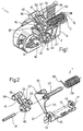
- Figure 1 shows a view in perspective, with parts removed for clarity, of a preferred embodiment of the handle according to the present invention;
- Figure 2 shows an exploded view in perspective, with parts removed for clarity, of the Figure 1 handle.
-
Number 1 in Figure 1 indicates a handle (shown partly) for controlling a vehicle door lock.Handle 1 comprises astructure 2, which is connected integrally, in known manner not described in detail, to a side door (not shown) of the vehicle. -
Structure 2, when fitted to the respective door, extends in a longitudinal direction, and comprises an intermediate portion 8 and a hollow end portion 9 adjacent to each other. Portions 9 and 8 carry respectivelateral appendixes holes longitudinal axis 15. - With reference to Figure 1,
handle 1 also comprises anexternal control lever 16, which is gripped by the user to open the respective lock (not shown), is hinged in known manner (not shown) tostructure 2, and carries anend arm 18.Arm 18 engages portion 9 and supports, on the end, atooth 19 extending, parallel toaxis 15, towards portion 8. - As shown in Figure 1 and particularly in Figure 2,
handle 1 also comprises a substantially C-shaped transmission lever 21, which is housed partly in portion 9, in turn comprises aportion 23 cooperating in sliding manner withtooth 19, and has one end hinged toappendixes pin 24 engagingholes tubular body 27 located betweenappendixes lever 21. -
Pin 24 enables lever 21 to rotate, aboutaxis 15, between an angular rest position (shown in Figure 1), and an angular work position to open the lock on the respective door whenlever 16 is activated by the user. -
Tubular body 27 is surrounded by a preloadedtorsion spring 28 interposed betweenlever 21 andstructure 2 to elastically restorelever 21 to the rest position. - As shown in the accompanying drawings,
handle 1 also comprises asafety retaining member 39 associated withlever 21 to retainlever 21 in the angular rest position and so prevent the lock from being released and the door from being opened spontaneously in the event of a collision in which the vehicle is struck side-on. -
Member 39 is formed in one piece, and comprises ahollow base portion 40housing appendix 10 and part oflever 21, and which is hinged toappendix 10 bypin 24 to rotate aboutaxis 15 with respect tolever 21. Aplatelike arm 41 extends radially outwards frombase portion 40, is substantially parallel to and shifted axially with respect tolever 21, and carries, on the free end, a cylindrical mass orcounterweight 42 extending longitudinally on opposite sides ofarm 41. -
Member 39 also comprises astop portion 52, which is located betweenaxis 15 andmass 42 and, in particular, is integral witharm 41 andbase portion 40, projects fromarm 41 in a direction parallel toaxis 15 and in a position facing alateral surface 53 oflever 21, and terminates with anappendix 55 defining a support for anarm 56 of spring 28 (Figure 2). - In actual use, in the absence of lateral impact,
spring 28 keepslever 21 in the rest position, andstop portion 52 resting against a corresponding intermediate portion oflateral surface 53 oflever 21. - Conversely, when the vehicle is struck from the side,
control lever 16 ofhandle 1 on the distressed door exerts ontransmission lever 21 an inertial opening moment to rotatelever 21 clockwise in Figure 1; and therespective mass 42, being located eccentrically with respect toaxis 15 and on the opposite side ofaxis 15 with respect totooth 19, exerts ontransmission lever 21 an inertial balancing moment to balance the inertial forces tending to movetransmission lever 21 into the work position. More specifically, the inertial balancing moment is opposite in direction to at least the force exerted bycontrol lever 16, and in the same direction as the elastic moment exerted byspring 28, and is such thattransmission lever 21 remains substantially static and the door closed. - In the event of lateral impact on one door, neither
control lever 16 normass 42 ofhandle 1 on the opposite door has any effect ontransmission lever 21. That is, the inertial forces acting on the opposite door handle keepcontrol lever 16 in the rest position and rotatemember 39 clockwise in Figure 1. Being permitted, however, to rotate freely in said direction with respect totransmission lever 21,member 39, as it rotates, simply loadsspring 28, without exerting any opening moment ontransmission lever 21, so thatlever 21 remains in the rest position and the door closed. - Unlike known handles,
handle 1 described therefore provides, in the event of lateral impact, for keeping all the side doors of the vehicle closed, regardless of which side of the vehicle is struck. - This is substantially due to the way in which
inertial mass 42 is connected totransmission lever 21, and, in particular, to the presence of a one-wayangular locking device 57 comprisingstop portion 52 andlateral surface 53, and which provides for makingmass 42 andtransmission lever 21 angularly integral with each other in one rotation direction aboutaxis 15, and for enablingmass 42 to rotate freely with respect to lever 21 in the opposite direction. - Despite comprising an
inertial mass 42 designed to simply rest ontransmission lever 21,handle 1 described is extremely silent-operating and efficient. That is,spring 28 resting onappendix 55, in normal operating conditions, holdsstop portion 52 againstlateral surface 53 at all times, thus preventing any annoying vibration; while the particular design ofbase portion 40 protects the hinge region from external agents, such as dust and water, thus preventing an increase in friction at the hinge region and, consequently, in response time in the event of impact. - Clearly, changes may be made to handle 1 as described and illustrated herein without, however, departing from the scope of the present invention as defined by the accompagnying claims.
- In particular,
member 39 may differ from the one described and illustrated by way of example, and be connected to a lock transmission lever other thanlever 21 described. - In particular,
transmission lever 21 andmember 39 may be connected tostructure 2 to rotate about two separate axes, e.g. to improve intervention time; andmember 39 may be held resting againsttransmission lever 21 by respective elastic elements separate fromspring 28, so as to prevent overly stressingspring 28.
Claims (8)
- A handle assembly (1) for a door of a vehicle, the handle comprising a transmission lever (21) activated externally by means of a control member (16) to rotate, about a first axis (15), between an angular rest position, in which a lock of said door cannot be opened and an angular work position to open said lock; and retaining means (39) for retaining said lever (21) in said rest position in the event of lateral impact on said vehicle; said retaining means comprising an inertial mass (42) associated with said lever (21) and located eccentrically with respect to said first axis (15) to exert a balancing force, in the event of lateral impact on the respective door, to balance the inertial forces tending to move said lever (21) into said work position; characterized in that said mass (42) rotates, with respect to said lever (21), about a second axis (15); and in that said retaining means (39) comprise one-way angular locking means (57) interposed between said mass (42) and said lever (21) to make said mass (42) angularly fixed with respect to said lever (21) and exert said balancing force in one rotation direction such that the transmission lever remains substantially static and the door closed, and to permit said mass (42) to rotate freely with respect to the lever (21) in the opposite direction.
- A handle assembly as claimed in Claim 1, characterized in that said first (15) and said second (15) axis are coincident with each other.
- A handle assembly as claimed in Claim 1 or 2, characterized in that said angular locking means (57) comprise a shoulder (53) carried by said lever (21); said mass (42) being positioned resting against said shoulder (53) .
- A handle assembly as claimed in Claim 3, characterized in that said mass (42) extends on the opposite side of said second axis (15) with respect to said shoulder (53).
- A handle assembly as claimed in Claim 3. or 4, characterized by comprising elastic forcing means (28) for keeping said mass (42) resting against said shoulder (53).
- A handle assembly as claimed in Claim 5, characterized by comprising elastic return means (28) for keeping said lever (21) in said rest position; said elastic return means (28) and said elastic forcing means (28) being defined by a single elastic element (28).
- A handle assembly as claimed in any one of the foregoing Claims, characterized by comprising a hollow portion (40) hinging said mass (42) about said second axis (15); said hollow portion (40) partly housing said lever (21).
- A handle assembly as claimed in Claim 7, characterized in that said mass (42) and said hollow portion (40) form part of a body (39) formed in one piece.
Applications Claiming Priority (2)
| Application Number | Priority Date | Filing Date | Title |
|---|---|---|---|
| IT1999TO000379A IT1309800B1 (en) | 1999-05-07 | 1999-05-07 | HANDLE FOR A VEHICLE DOOR |
| ITTO990379 | 1999-05-07 |
Publications (4)
| Publication Number | Publication Date |
|---|---|
| EP1050644A2 EP1050644A2 (en) | 2000-11-08 |
| EP1050644A3 EP1050644A3 (en) | 2001-03-21 |
| EP1050644A9 EP1050644A9 (en) | 2001-05-02 |
| EP1050644B1 true EP1050644B1 (en) | 2006-02-15 |
Family
ID=11417793
Family Applications (1)
| Application Number | Title | Priority Date | Filing Date |
|---|---|---|---|
| EP00109651A Expired - Lifetime EP1050644B1 (en) | 1999-05-07 | 2000-05-05 | Vehicle door handle |
Country Status (5)
| Country | Link |
|---|---|
| EP (1) | EP1050644B1 (en) |
| JP (1) | JP4629187B2 (en) |
| DE (1) | DE60025970T2 (en) |
| ES (1) | ES2258424T3 (en) |
| IT (1) | IT1309800B1 (en) |
Families Citing this family (12)
| Publication number | Priority date | Publication date | Assignee | Title |
|---|---|---|---|---|
| US6565134B1 (en) * | 2000-04-21 | 2003-05-20 | Adac Plastics, Inc. | Handle with side impact counterweight having installation position |
| ITMI20022250A1 (en) * | 2002-10-23 | 2004-04-24 | Valeo Sicurezza Abitacolo Spa | DOOR HANDLE, DOORS OR SIMILAR, IN PARTICULAR |
| CN100450832C (en) * | 2004-02-23 | 2009-01-14 | 伊利诺斯器械工程公司 | Inertia-activated mechanism |
| KR100704592B1 (en) * | 2005-08-24 | 2007-04-06 | 기아자동차주식회사 | Door module |
| KR100737001B1 (en) | 2005-10-07 | 2007-07-09 | 현대자동차주식회사 | Safety mechanism of vehicle door handle assembly |
| JP4881717B2 (en) * | 2006-12-25 | 2012-02-22 | 株式会社アルファ | Automotive door handle device |
| KR100812439B1 (en) | 2007-04-02 | 2008-03-10 | 현대자동차주식회사 | Opening operation control device of door out side handle by side inertia force |
| KR20090040769A (en) * | 2007-10-22 | 2009-04-27 | 현대자동차주식회사 | Door handle release prevention device |
| EP2314811B1 (en) | 2009-10-26 | 2012-07-04 | Valeo S.p.A. | Paddle-type handle comprising an inertia system |
| KR101449265B1 (en) * | 2013-04-10 | 2014-10-08 | 현대자동차주식회사 | Device for preventing door open of vehicle |
| DE102018116325A1 (en) * | 2018-07-05 | 2020-01-09 | Kiekert Ag | Lock for a motor vehicle |
| US20250270857A1 (en) * | 2024-02-23 | 2025-08-28 | Witte Automotive Gmbh | Door handle |
Family Cites Families (2)
| Publication number | Priority date | Publication date | Assignee | Title |
|---|---|---|---|---|
| GB1219234A (en) * | 1968-03-06 | 1971-01-13 | Daimler Benz Ag | A vehicle door lock |
| DE2023859C3 (en) * | 1970-05-15 | 1978-10-19 | Daimler-Benz Ag, 7000 Stuttgart | Blocking device for a motor vehicle door lock |
-
1999
- 1999-05-07 IT IT1999TO000379A patent/IT1309800B1/en active
-
2000
- 2000-05-05 EP EP00109651A patent/EP1050644B1/en not_active Expired - Lifetime
- 2000-05-05 ES ES00109651T patent/ES2258424T3/en not_active Expired - Lifetime
- 2000-05-05 DE DE60025970T patent/DE60025970T2/en not_active Expired - Lifetime
- 2000-05-08 JP JP2000139416A patent/JP4629187B2/en not_active Expired - Lifetime
Also Published As
| Publication number | Publication date |
|---|---|
| EP1050644A9 (en) | 2001-05-02 |
| EP1050644A2 (en) | 2000-11-08 |
| ITTO990379A0 (en) | 1999-05-07 |
| DE60025970D1 (en) | 2006-04-20 |
| DE60025970T2 (en) | 2006-11-02 |
| IT1309800B1 (en) | 2002-01-30 |
| ES2258424T3 (en) | 2006-09-01 |
| JP4629187B2 (en) | 2011-02-09 |
| JP2001132282A (en) | 2001-05-15 |
| ITTO990379A1 (en) | 2000-11-07 |
| EP1050644A3 (en) | 2001-03-21 |
Similar Documents
| Publication | Publication Date | Title |
|---|---|---|
| US6382688B1 (en) | Vehicle door handle | |
| EP1050644A2 (en) | Vehicle door handle | |
| US5743575A (en) | Fluid-damped automotive door latch actuator | |
| JP6528028B2 (en) | Vehicle door handle safety device | |
| EP3075929B1 (en) | Door handle device for vehicle | |
| EP2980343B1 (en) | Door handle apparatus for vehicle | |
| KR101457717B1 (en) | Vehicle handle with safety device | |
| US9970221B2 (en) | Door handle assembly for motor vehicle | |
| EP1050640B1 (en) | Vehicle door handle | |
| CN110709573B (en) | Hinge with opening device for furniture | |
| KR101393814B1 (en) | Vehicle handle with a security device | |
| JP2020531717A (en) | Locking system with handle and remote inertial system | |
| EP1052355A2 (en) | Vehicle door handle | |
| EP1624139B1 (en) | Door handle device | |
| KR101242767B1 (en) | Assist handle damper for vehicle | |
| KR100715030B1 (en) | Hinge module for rice cooker | |
| EP3636864B1 (en) | Vehicle door lock device and vehicle door lock set | |
| JP2005232768A (en) | Door handle device for vehicle | |
| US20250034913A1 (en) | Inertial safety system for a vehicle door handle | |
| JPH10114352A (en) | Open lock mechanism for cover member | |
| KR100892508B1 (en) | Automotive Door Handle Assemblies | |
| KR200324654Y1 (en) | door check | |
| KR20060006458A (en) | Armrest Angle Adjuster | |
| KR100868155B1 (en) | Locking device for car sunglasses case | |
| JP2003003711A (en) | Door lock |
Legal Events
| Date | Code | Title | Description |
|---|---|---|---|
| PUAI | Public reference made under article 153(3) epc to a published international application that has entered the european phase |
Free format text: ORIGINAL CODE: 0009012 |
|
| AK | Designated contracting states |
Kind code of ref document: A2 Designated state(s): DE ES FR GB |
|
| AX | Request for extension of the european patent |
Free format text: AL;LT;LV;MK;RO;SI |
|
| PUAL | Search report despatched |
Free format text: ORIGINAL CODE: 0009013 |
|
| AK | Designated contracting states |
Kind code of ref document: A3 Designated state(s): AT BE CH CY DE DK ES FI FR GB GR IE IT LI LU MC NL PT SE |
|
| AX | Request for extension of the european patent |
Free format text: AL;LT;LV;MK;RO;SI |
|
| RAP3 | Party data changed (applicant data changed or rights of an application transferred) |
Owner name: VALEO SICUREZZA ABITACOLO S.P.A. |
|
| 17P | Request for examination filed |
Effective date: 20010917 |
|
| AKX | Designation fees paid |
Free format text: DE ES FR GB |
|
| 17Q | First examination report despatched |
Effective date: 20031009 |
|
| GRAP | Despatch of communication of intention to grant a patent |
Free format text: ORIGINAL CODE: EPIDOSNIGR1 |
|
| GRAS | Grant fee paid |
Free format text: ORIGINAL CODE: EPIDOSNIGR3 |
|
| GRAA | (expected) grant |
Free format text: ORIGINAL CODE: 0009210 |
|
| AK | Designated contracting states |
Kind code of ref document: B1 Designated state(s): DE ES FR GB |
|
| REG | Reference to a national code |
Ref country code: GB Ref legal event code: FG4D |
|
| REF | Corresponds to: |
Ref document number: 60025970 Country of ref document: DE Date of ref document: 20060420 Kind code of ref document: P |
|
| ET | Fr: translation filed | ||
| REG | Reference to a national code |
Ref country code: ES Ref legal event code: FG2A Ref document number: 2258424 Country of ref document: ES Kind code of ref document: T3 |
|
| PLBE | No opposition filed within time limit |
Free format text: ORIGINAL CODE: 0009261 |
|
| STAA | Information on the status of an ep patent application or granted ep patent |
Free format text: STATUS: NO OPPOSITION FILED WITHIN TIME LIMIT |
|
| 26N | No opposition filed |
Effective date: 20061116 |
|
| REG | Reference to a national code |
Ref country code: GB Ref legal event code: 732E Free format text: REGISTERED BETWEEN 20160317 AND 20160323 |
|
| REG | Reference to a national code |
Ref country code: ES Ref legal event code: PC2A Owner name: U-SHIN ITALIA S.P.A. Effective date: 20160427 |
|
| REG | Reference to a national code |
Ref country code: FR Ref legal event code: PLFP Year of fee payment: 17 |
|
| REG | Reference to a national code |
Ref country code: FR Ref legal event code: PLFP Year of fee payment: 18 |
|
| REG | Reference to a national code |
Ref country code: DE Ref legal event code: R082 Ref document number: 60025970 Country of ref document: DE Representative=s name: PRINZ & PARTNER MBB PATENTANWAELTE RECHTSANWAE, DE Ref country code: DE Ref legal event code: R081 Ref document number: 60025970 Country of ref document: DE Owner name: U-SHIN ITALIA S.P.A., IT Free format text: FORMER OWNER: VALEO SICUREZZA ABITACOLO, SANTENA, IT |
|
| REG | Reference to a national code |
Ref country code: FR Ref legal event code: PLFP Year of fee payment: 19 |
|
| PGFP | Annual fee paid to national office [announced via postgrant information from national office to epo] |
Ref country code: ES Payment date: 20190606 Year of fee payment: 20 Ref country code: DE Payment date: 20190510 Year of fee payment: 20 |
|
| PGFP | Annual fee paid to national office [announced via postgrant information from national office to epo] |
Ref country code: FR Payment date: 20190531 Year of fee payment: 20 |
|
| PGFP | Annual fee paid to national office [announced via postgrant information from national office to epo] |
Ref country code: GB Payment date: 20190516 Year of fee payment: 20 |
|
| REG | Reference to a national code |
Ref country code: DE Ref legal event code: R071 Ref document number: 60025970 Country of ref document: DE |
|
| REG | Reference to a national code |
Ref country code: GB Ref legal event code: PE20 Expiry date: 20200504 |
|
| PG25 | Lapsed in a contracting state [announced via postgrant information from national office to epo] |
Ref country code: GB Free format text: LAPSE BECAUSE OF EXPIRATION OF PROTECTION Effective date: 20200504 |
|
| REG | Reference to a national code |
Ref country code: ES Ref legal event code: FD2A Effective date: 20200904 |
|
| PG25 | Lapsed in a contracting state [announced via postgrant information from national office to epo] |
Ref country code: ES Free format text: LAPSE BECAUSE OF EXPIRATION OF PROTECTION Effective date: 20200506 |