EP1050366A2 - Zuführmechanismus - Google Patents
Zuführmechanismus Download PDFInfo
- Publication number
- EP1050366A2 EP1050366A2 EP00109269A EP00109269A EP1050366A2 EP 1050366 A2 EP1050366 A2 EP 1050366A2 EP 00109269 A EP00109269 A EP 00109269A EP 00109269 A EP00109269 A EP 00109269A EP 1050366 A2 EP1050366 A2 EP 1050366A2
- Authority
- EP
- European Patent Office
- Prior art keywords
- feed
- bars
- mechanism according
- feed mechanism
- feed bars
- Prior art date
- Legal status (The legal status is an assumption and is not a legal conclusion. Google has not performed a legal analysis and makes no representation as to the accuracy of the status listed.)
- Withdrawn
Links
- 230000007246 mechanism Effects 0.000 title claims abstract description 51
- 238000000034 method Methods 0.000 claims abstract description 7
- 230000008569 process Effects 0.000 claims abstract description 7
- 241000220317 Rosa Species 0.000 claims description 6
- 238000000926 separation method Methods 0.000 claims description 6
- 230000000994 depressogenic effect Effects 0.000 claims description 3
- ATJFFYVFTNAWJD-UHFFFAOYSA-N Tin Chemical compound [Sn] ATJFFYVFTNAWJD-UHFFFAOYSA-N 0.000 abstract description 25
- 238000004519 manufacturing process Methods 0.000 abstract description 12
- 239000002184 metal Substances 0.000 abstract description 3
- 238000006073 displacement reaction Methods 0.000 abstract description 2
- 230000000694 effects Effects 0.000 description 3
- 229910000831 Steel Inorganic materials 0.000 description 2
- 239000011324 bead Substances 0.000 description 2
- 230000001419 dependent effect Effects 0.000 description 2
- 230000009467 reduction Effects 0.000 description 2
- 239000010959 steel Substances 0.000 description 2
- 244000269722 Thea sinensis Species 0.000 description 1
- 244000299461 Theobroma cacao Species 0.000 description 1
- 230000008901 benefit Effects 0.000 description 1
- 230000015572 biosynthetic process Effects 0.000 description 1
- 235000015895 biscuits Nutrition 0.000 description 1
- 230000008859 change Effects 0.000 description 1
- 235000019219 chocolate Nutrition 0.000 description 1
- 235000016213 coffee Nutrition 0.000 description 1
- 235000013353 coffee beverage Nutrition 0.000 description 1
- 238000010586 diagram Methods 0.000 description 1
- 230000001788 irregular Effects 0.000 description 1
- 239000000463 material Substances 0.000 description 1
- 229920003023 plastic Polymers 0.000 description 1
- 239000004033 plastic Substances 0.000 description 1
- 230000000717 retained effect Effects 0.000 description 1
- 235000013616 tea Nutrition 0.000 description 1
- 230000007723 transport mechanism Effects 0.000 description 1
Images


Classifications
-
- B—PERFORMING OPERATIONS; TRANSPORTING
- B21—MECHANICAL METAL-WORKING WITHOUT ESSENTIALLY REMOVING MATERIAL; PUNCHING METAL
- B21D—WORKING OR PROCESSING OF SHEET METAL OR METAL TUBES, RODS OR PROFILES WITHOUT ESSENTIALLY REMOVING MATERIAL; PUNCHING METAL
- B21D51/00—Making hollow objects
- B21D51/16—Making hollow objects characterised by the use of the objects
- B21D51/26—Making hollow objects characterised by the use of the objects cans or tins; Closing same in a permanent manner
-
- B—PERFORMING OPERATIONS; TRANSPORTING
- B23—MACHINE TOOLS; METAL-WORKING NOT OTHERWISE PROVIDED FOR
- B23Q—DETAILS, COMPONENTS, OR ACCESSORIES FOR MACHINE TOOLS, e.g. ARRANGEMENTS FOR COPYING OR CONTROLLING; MACHINE TOOLS IN GENERAL CHARACTERISED BY THE CONSTRUCTION OF PARTICULAR DETAILS OR COMPONENTS; COMBINATIONS OR ASSOCIATIONS OF METAL-WORKING MACHINES, NOT DIRECTED TO A PARTICULAR RESULT
- B23Q7/00—Arrangements for handling work specially combined with or arranged in, or specially adapted for use in connection with, machine tools, e.g. for conveying, loading, positioning, discharging, sorting
- B23Q7/06—Arrangements for handling work specially combined with or arranged in, or specially adapted for use in connection with, machine tools, e.g. for conveying, loading, positioning, discharging, sorting by means of pushers
-
- B—PERFORMING OPERATIONS; TRANSPORTING
- B23—MACHINE TOOLS; METAL-WORKING NOT OTHERWISE PROVIDED FOR
- B23Q—DETAILS, COMPONENTS, OR ACCESSORIES FOR MACHINE TOOLS, e.g. ARRANGEMENTS FOR COPYING OR CONTROLLING; MACHINE TOOLS IN GENERAL CHARACTERISED BY THE CONSTRUCTION OF PARTICULAR DETAILS OR COMPONENTS; COMBINATIONS OR ASSOCIATIONS OF METAL-WORKING MACHINES, NOT DIRECTED TO A PARTICULAR RESULT
- B23Q7/00—Arrangements for handling work specially combined with or arranged in, or specially adapted for use in connection with, machine tools, e.g. for conveying, loading, positioning, discharging, sorting
- B23Q7/14—Arrangements for handling work specially combined with or arranged in, or specially adapted for use in connection with, machine tools, e.g. for conveying, loading, positioning, discharging, sorting co-ordinated in production lines
Definitions
- This invention relates to a feed mechanism, and more specifically to a feed mechanism specifically adapted for use in machinery for the automated manufacture of tin boxes.
- Automated tin box manufacture is accomplished by juxtaposing several different pieces of machinery and providing transfer means therebetween. Tin boxes can be manufactured in a vast number of different shapes and sizes and accordingly a single piece of machinery is required to be sufficiently versatile to enable manufacture of tin boxes in a large number of said shapes and sizes. It will be understood by those skilled in the art that the machinery used has a number of different components which can be exchanged to facilitate the manufacture of different boxes and currently the length of time taken to exchange all these various components to enable a particular set of machines to manufacture a different box shape can be up to an entire day.
- the invention hereinafter set forth, and also set forth in our co-pending applications have as their object the reduction of this time. Any reduction achievable in the "changeover" time is especially desirable when it is considered that tin box production rates using the machinery described hereinafter may reach 40 per minute.
- Tin boxes can contain a wide variety of different goods, such as bottles, chocolates, biscuits, tea, coffee and the like. Manufacturers of such products commonly consider the containment of their product in tins because of the rigidity and durability which the sheet steel, from which such tins are commonly made, provides. Additionally, the containment of a product in a tin box may also suggest that the product therein is of a certain quality, especially as ornate and detailed print effects can be obtained on the surface of the metal plates from which the tin boxes are manufactured. Such effects cannot be achieved, or are achieved only to a much lesser degree by the containment of products in cardboard cartons or receptacles of plastics materials. A tin box in which such a product is contained has the further advantage of being reusable to contain other household items such as screws, nuts bolts, pencils and pens, etc. after the product originally contained therein has been consumed or otherwise utilised.
- the first stage in the process of automated tin box manufacture is the profiling of a simple sheet steel, and generally rectangular, blank from which the walls of the tin box are ultimately constituted.
- the blank is fed through an "Automatic Notching, Curling and Beading" machine, referred to hereinafter as an ANCB machine.
- This machine consists of a plurality of consecutively driven rollers disposed both above and below the blank as it passes therebetween, each of said rollers performing a forming step on the blank.
- each blank as it exits the ANCB machine depends on the ultimate shape of the tin, but in general the blank is substantially flat with the exception of a hem provided parallel with one of the longer edges of the blank and proximate thereto, a bead is provided on one of said longer edges, a partial curl is provided around the alternate longer edge, and a pair of hooks oppositely disposed with respect to one another on the shorter edges.
- the ANCB machine has cutting means which notch the corners of the blank to preclude any interference effects which may be caused by said corners either when the blank is profiled and provided with the hooks along its shorter edges, when it is formed into the cross-sectional shape of the tin box, or when wrapped around and attached to the base of said tin box.
- the hem provides a surface behind which the beaded lip of a tin lid can engage to inhibit the removal of a lid separately formed and applied around the uppermost edge of the tin box, the bead is provided to hide the sharp longer edge of the blank which ultimately forms said uppermost edge of the tin box, the partial curl on the alternate longer edge of the blank is provided to facilitate the attachment of the blank, after same has been formed into the desired cross-sectional shape, to the base of the tin box, and the hooks provided along the shorter edges of the blank facilitate the connection of said edges to one another after the forming operation.
- the bodymaker may be responsible for the formation of the hooks on the shorter edges of the blank to facilitate connection of said edges to one another.
- the profiled blank is then fed from the ANCB machine into a bodymaker by a feed mechanism forming an integral part of the bodymaker which generally comprises a pair of reciprocating feed bars whose motion is best described as being that of a "walking beam" in conjunction with ''disappearing guides'' which simultaneously urge the profiled blank towards and over a forming mandrel and precisely align said blank thereon.
- the disappearing guides are rotated away from the blank when it is held in contact with the uppermost portion of the mandrel, which is generally of similar shape to the desired cross-sectional shape of the tin box to be manufactured, by a mandrel clamping arrangement.
- the removal of the disappearing guides allows a pair of forming wings pivotally connected together and disposed above the mandrel to rotate about their pivot and form said blank, which is at this stage still substantially planar, around the said mandrel.
- the forming operation performed by the wings also constrains the oppositely disposed hooks on the shorter edges of the blank to interlock on the underside of the mandrel whereupon a second forming tool compresses the metal of the blank in the interlocked region to form the vertical seam within the wall of the tin box.
- the blank is clamped against the upper surface of said mandrel by said mandrel clamping arrangement.
- This invention is specifically concerned with the provision of a novel feed mechanism.
- the feed mechanism currently used to transfer the pressed blanks from the ANCB machine through the bodymaker is now described.
- the profiled but substantially planar blanks exit the ANCB machine onto a pair of pivotable drop rails which both guide and support the blank as it travels until it contacts a stopping member.
- the pivotable guide rails are actuated with a predetermined frequency which corresponds to the rate at which the profiled blanks are fed into and exit the ANCB machine and also to the rate at which the said blanks can be fed through the bodymaker.
- both drop rails swing outwardly and away from each other such that the blank supported thereby falls onto a pair of parallel feed bars disposed with a feed table, said feed bars reciprocally travelling in a "walking beam” type manner in a direction perpendicular to the direction of travel of the blanks exiting the ANCB machine.
- Each of said feed bars is provided with a plurality of spring loaded pawls which engage behind one of the edges of the blank as it rests thereon or on the feed table, and these pawls urge the blank through the bodymaking machine.
- the feed table on which the blank travels is generally symmetrical about an axis parallel to the direction of travel of the blanks thereon and is substantially hollow to allow the feed bars and driving machinery to operate unhindered therein.
- the feed bars are rigidly secured with bolts or the like to a feed bar transport supported and freely slidable on horizontal guide rails whose length is marginally less than the length of the feed mechanism.
- the feed bars are sufficiently separated to provide a certain degree of stability for the blanks being transported thereon into the bodymaker, the requirement for precision placement of the blanks on the mandrel of the bodymaker is such that stationary guide means are also required at each side of the feed bars to ensure that the orientation and positioning of the blank on said feed bars is correct. Accordingly, such guide means are rigidly secured to the feed table and come into contact with the edges of the blank which are perpendicular to that behind which the pawls are engaged.
- each feed bar there are a plurality of spring loaded pawls provided on each feed bar and in general there are three pairs of pawls, the pawls of each pair being disposed a predetermined distance from an end of the particular feed bar which is dependent on the length of travel of the said feed bars and also on the size of the blank supported thereby.
- the purpose of providing three pairs of pawls is to allow for three separate blanks to be simultaneously moved by said feed bars, each blank being at a different position thereon and being moved by a separate pair of pawls engaged behind one of the edges of said blank.
- the direction of travel of said bars reverses.
- the blanks do not however return to their original positions with the feed bars as the pair of opposite edges of said blanks on either side of and parallel with the feed bars frictionally engage the guide means which retain the blank in that position.
- the spring loading of the pawls, their profiled shape and their pivotable mounting within the feed bars allows said pawls to slide under the leading edge of the blanks retained in the guide means and springingly emerge in front of the opposite trailing edge with which the hooked portions of the pawl can engage to urge said blank along the feed table.
- the blanks are intermittently moved forward on the feed table and through the bodymaking machine on the reciprocating feed bars.
- the blank feed mechanism described above is adequate for transfering blanks of a particular size and shape from the ANCB machine to the bodymaker, but as described above all those machines involved in the automated manufacture of tin boxes are required to be sufficiently versatile to accommodate blanks and bases of different sizes and shapes, and the feed mechanism described is severely disadvantaged in this respect.
- the feed bars must be capable of being displaced towards or away from one another within the feed table to permit the transfer of smaller or larger blanks, and the position of the guide means on either side of the feed bars must also be capable of being altered.
- each of these components can be rigidly secured to the transfer table and feed table respectively after movement to ensure continued precise operation of the transfer mechanism.
- an anvil In current feed mechanisms an anvil is rigidly secured by bolts to either side of the transfer table and it is to said anvils that the feed bars are attached, also with bolts, and symmetrically of the transfer table.
- the anvils are provided with a plurality of attachment locations to allow said feed bars to be attached thereto at a number of different separations to allow for the transfer of blanks of different sizes thereon.
- the intricacy of the machinery surrounding the transfer table, anvils and feed bars makes the changeover process unavoidably time consuming.
- a feed mechanism comprising a stationary feed table within which is disposed a driven transfer table to which a first support means is attached, a further second support means being provided within the feed table at a separation distance from said first support means, characterised in that first and/or second support means are connected by telescopic means whose extension can be altered and securely set.
- both the first and second support means are connected by telescopic means whose extension can be altered and securely set.
- the support means are longitudinal feed bars which are parallel.
- the transfer table is reciprocally driven and thus imparts reciprocal motion to the said first feed bar and concomitantly to said second feed bar through its telescopic connection with the first.
- feed bars are provided with pawls which engage behind the bodies which the feed mechanism is adapted to move to move same when said reciprocating motion is in a forward direction, and which slide underneath the said bodies when said reciprocating motion is in a reverse direction.
- the pawls are spring biased and can be depressed so as to be flush with the upper surface of the feed bars when sliding underneath the said bodies which are frictionally held along a pair of opposite edges and thus do not slide in the reverse direction with said feed bars.
- the transfer table is provided with guide bars which extend perpendicularly to the direction of travel of said transfer table and towards and underneath the feed bars, and which are provided with location means to ensure the parallel orientation of said feed bars.
- connection of the telescopic means to the transfer table at one end of said telescopic means, and to the feed bars at their alternate ends is effected using rose bearings which allow a degree of play during the alignment process.
- the feed bars can be disposed at one of a number of distances from the transfer table, and further preferably each feed bar can be disposed in one of five different positions.
- the motion of bodies to be transferred between one location and another by said feed mechanism is discontinuous and discrete as is required in automated processes which comprise a number of discrete steps, but the ease, simplicity and speed with which the feed mechanism can be altered to accommodate blanks of different shapes and sizes is drastically increased using the telescopic means as described above and hereinafter.
- the rose bearings which connect the telescopic member and also the extension lock thereon are simply loosened, the feed bars are then lifted from one position and moved towards or away from the transfer table as required and dropped back into one of the alternate locations provided by the guide bars.
- the bearings and the extension lock of the telescopic members are then tightened to lock the feed bars in position.
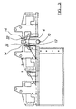
- FIG. 1 there is shown a feed mechanism indicated generally at 2 comprising a stationary feed table 4 and a driven transfer table 6 which is constrained to travel along a line substantially parallel with the central axis 8 of the table 4.
- the transfer table 6 slides along guides 10, 12 which are clearly shown in Figure 3.
- a first feed bar 14 and a second feed bar 16 are connected to said transfer table by means of diagonally disposed telescopic cylinders, one of which is shown at 18, from which a piston rod 20 protrudes.
- the cylinder 18 and the rod 20 are provided at their ends with rose bearings 22, 24 which allow a certain degree of play between the respective components when loose. This ensures both that a safe angle of inclination of the diagonal telescopic member can be achieved between the transfer table and said second feed bar (to prevent any jack-knifing or other undesirable jamming during the reciprocal motion of the transfer table), and also allows said second feed bar to be jostled slightly during position thereof to ensure that it can be dropped into an alternate location without requiring disconnection from said piston rod 20. It should be mentioned that the connection of the first feed bar 14 using rose bearing as described above with reference to the second feed bar is generally identical.
- the telescopic cylinder 18 is provided with extension locking means (not shown) which can be tightened up to ensure that the orientation of feed bar 16 with respect to the feed bar 14 is maintained after alignment. Additionally, the element of play provided by the rose bearings can be eradicated by suitable tightening thereof before operation of the feed mechanism.
- the feed bars 14, 16 are of identical length and their ends are aligned so that spring loaded pawls 26, 28, 30 on the first feed bar 14 are in alignment with identically disposed pawls 32, 34, 36 provided on the second feed bar 16.
- a lug 38 provided a the rear end of the first feed bar is in alignment with a similar lug 40.
- a simple reciprocating drive mechanism 42 comprising a connection rod 44 and a drive member 46 is connected to the transfer table 6 at 48 and the rotational motion of an eccentric drive shaft (not shown) to which the connection rod is connected thus urges said transfer table, and thus both feed bars back and forth as shown at 50.
- the feed bars 14, 16 are at the extremity of their forward motion, and on the point of returning towards a position in which the first portion of their lengths defined between the lugs 38, 40 and the most rearward pawls 30, 36 is disposed entirely underneath a blank drop mechanism 60.
- profiled blanks exit an ANCB machine and are supported above the feed mechanism by a pair of drop rails 62, 64 which, on actuation the timing of which is dependent on the motion of the reciprocation mechanism 42, rotate outwardly of one another to drop the said blank onto the feed bars which are at that time disposed underneath said drop mechanism.
- the lugs 38, 40 engage behind an edge of said blank and urge same onto the feed table 4 where the pair opposite edges of said blank which are perpendicular to the edge behind which the lugs engage come into frictional contact with edge retaining means (not shown) disposed on said feed table.
- the feed mechanism and the feed bars shown in the figures are configured to support three separate blanks at any one time, and at the extremity of forward travel of said feed bars, a fourth blank 72 is urged off the table 4 and into region of the bodymaking machine comprising the forming tools (not shown).
- the pawls 26, 28, 30, 32, 34 ,36 are spring loaded to protrude above the upper surface of the feed bars 14, 16 but when the feed bars move in their reverse direction as shown at 74, the front side of said pawls is inclined such that they are depressed into recesses provided in the feed bars by the leading edges 67, 69, 71 of the blanks and thus the blanks remain stationary during such reverse motion.
- the pawls only emerge again behind the trailing edge of the blank immediately preceding that which was caused to move forward by that particular pair of pawls.
- a drop rail actuation mechanism 80 ensures that the drop rails 62, 64 rotate outwardly to drop a blank supported thereby onto the feed bars only when said feed bars are at the extremity of their rearward travel and thus correctly disposed underneath said drop rails.
- the guide means 90, 92 may be moved laterally towards and away from the central axis 8 as required by the particular dimensions, the shape of the blank being transferred, and the particular configuration and location of the blank drop mechanism 60.
- the flexibility offered by the feed table arrangement described herein is enhanced in that the guide means 90, 92 are ideally servo-controlled and precisely moveable within lateral channels 94, 96, 98, 100. This facility allows for particularly quick re-setting of the machine components to enable a differently sized and shaped blank to be translated thereover.
- the feed mechanism is further enhanced in that the feed bars are disposed and freely movable in guide bars (not shown in the interests of clarity) which both support the feed bars and constrain their motion to be precisely parallel with the central axis 8 of the feed table.
- said guide bars provide lateral support for the feed bars along substantially their entire length to prevent any lateral sway, judder or whipping of said feed bars as they are moved rapidly and reciprocally within the table.
- These guide bars are provided internally with roller bearings to allow substantially frictionless motion of the feed bars therewithin and with spigots on their lowermost surfaces which are received in a plurality of aperture pairs drilled in the feed table upper surface on either side of the central axis shown for one side of the table at 102, 104, 106, 108, 110. It will be appreciated that said aperture pairs could be replaced with pairs of lateral slots which would allow the feed bars to assume a practically infinite number of lateral displacements from the central axis of the table.
- the guide bars can be securely affixed to the stationary feed table in one of a plurality of locations and this further increases the flexibility and versatility of the table. Indeed, by this arrangement either feed bar can be disposed at one of a number (possibly infinite as mentioned above) of distances from the transfer table determined by the lateral distance of the aperture pairs drilled in the feed table from said central axis. This ensures that the blanks are translated reliably and without hindrance in a precisely linear fashion over the table without snagging or twisting. Furthermore, the various components of the machine can be altered to ensure that the pawls engaged behind the edges of the blanks are substantially symmetrically disposed of the central axis of the blank to avoid any twisting motion of said blank.
Landscapes
- Engineering & Computer Science (AREA)
- Mechanical Engineering (AREA)
- Making Paper Articles (AREA)
Applications Claiming Priority (4)
| Application Number | Priority Date | Filing Date | Title |
|---|---|---|---|
| GBGB9910061.2A GB9910061D0 (en) | 1999-05-01 | 1999-05-01 | Feed mechanism |
| GB9910061 | 1999-05-01 | ||
| GBGB9912262.4A GB9912262D0 (en) | 1999-05-27 | 1999-05-27 | Feed mechanism |
| GB9912262 | 1999-05-27 |
Publications (3)
| Publication Number | Publication Date |
|---|---|
| EP1050366A2 true EP1050366A2 (de) | 2000-11-08 |
| EP1050366A3 EP1050366A3 (de) | 2002-01-02 |
| EP1050366A9 EP1050366A9 (de) | 2002-04-10 |
Family
ID=26315492
Family Applications (1)
| Application Number | Title | Priority Date | Filing Date |
|---|---|---|---|
| EP00109269A Withdrawn EP1050366A3 (de) | 1999-05-01 | 2000-04-28 | Zuführmechanismus |
Country Status (2)
| Country | Link |
|---|---|
| US (1) | US6481261B1 (de) |
| EP (1) | EP1050366A3 (de) |
Cited By (4)
| Publication number | Priority date | Publication date | Assignee | Title |
|---|---|---|---|---|
| ES2268989A1 (es) * | 2005-08-22 | 2007-03-16 | Comasur 2000, S.L.L. | Manipulador para chapas de hojalata tratadas. |
| US8394335B2 (en) | 2009-03-06 | 2013-03-12 | Allpax Products Llc | Drive train for agitation of products in batch retorts and related retort system |
| US9155332B2 (en) | 2011-08-10 | 2015-10-13 | Allpax Products Llc | Retort with progressive latch, roller support arrangement and method and system for reciprocation of loads |
| CN113909977A (zh) * | 2021-10-29 | 2022-01-11 | 浙江海格威液压科技有限公司 | 一种上料机构及液压管接头加工流水线 |
Families Citing this family (6)
| Publication number | Priority date | Publication date | Assignee | Title |
|---|---|---|---|---|
| US7351767B2 (en) * | 2004-02-20 | 2008-04-01 | Chevron Phillips Chemical Company, Lp | Composition for monovinylrenic-based shrink label films |
| US7737216B2 (en) * | 2006-01-26 | 2010-06-15 | Chevron Phillips Chemical Company Lp | Monovinylarene conjugated diene block copolymer compositions for shrinkable films |
| US20080183326A1 (en) * | 2007-01-26 | 2008-07-31 | Danelski Darin L | Automatic A-Frame Picking System |
| US20120024669A1 (en) | 2010-07-29 | 2012-02-02 | Danelski Darin L | Networked Motorized Drive Roller Conveyor |
| US10229383B2 (en) | 2012-02-05 | 2019-03-12 | Matthews International Corporation | Perpetual batch order fulfillment |
| US9446908B2 (en) | 2012-02-05 | 2016-09-20 | Matthews Resources, Inc. | Conveying systems and methods of associating data with an item transported by a conveying system |
Family Cites Families (13)
| Publication number | Priority date | Publication date | Assignee | Title |
|---|---|---|---|---|
| US3552629A (en) * | 1969-07-07 | 1971-01-05 | Bliss Co | Method and machine for forming lap welded aluminum can bodies |
| US3811522A (en) | 1973-04-19 | 1974-05-21 | Reliance Electric Co | Machine for weighing, printing and punching workpieces |
| US4199288A (en) | 1977-07-25 | 1980-04-22 | Ganz Brothers, Inc. | Infinitely variable spacing feeder |
| US4269015A (en) * | 1979-06-14 | 1981-05-26 | Fmc Corporation | Apparatus for packaging articles in a wire-bound box assembly |
| US4382737A (en) * | 1981-03-05 | 1983-05-10 | Gulf & Western Manufacturing Company | Can end making apparatus |
| US4382395A (en) * | 1981-04-02 | 1983-05-10 | Thomas Haar | Loading device for a machine tool, particularly for machining panels of sheet metal or other materials |
| US4607516A (en) * | 1982-09-03 | 1986-08-26 | Danly Machine Corporation | Transfer feed press with improved transfer feed system |
| JPS59106643U (ja) | 1982-12-28 | 1984-07-18 | 株式会社小松製作所 | トランスフアフイ−ダのトランスフアバ閉寸法調整装置 |
| CH673604A5 (de) * | 1987-10-22 | 1990-03-30 | Fael Sa | |
| DE59303061D1 (de) | 1992-06-29 | 1996-08-01 | Elpatronic Ag | Verfahren zum Zuführen von Dosenzargen zu einer Dosenschweissstation sowie Vorrichtung zu dessen Durchführung |
| JP2708368B2 (ja) * | 1994-06-15 | 1998-02-04 | 株式会社サンコー製作所 | 長尺材の截断装置 |
| GB9421196D0 (en) | 1994-10-20 | 1994-12-07 | Riverwood Int Ltd | Spacing conveyor mechanism |
| US6012312A (en) * | 1998-09-14 | 2000-01-11 | Budd Canada, Inc. | Double blank detector apparatus and method of operation |
-
2000
- 2000-04-28 US US09/560,748 patent/US6481261B1/en not_active Expired - Fee Related
- 2000-04-28 EP EP00109269A patent/EP1050366A3/de not_active Withdrawn
Cited By (6)
| Publication number | Priority date | Publication date | Assignee | Title |
|---|---|---|---|---|
| ES2268989A1 (es) * | 2005-08-22 | 2007-03-16 | Comasur 2000, S.L.L. | Manipulador para chapas de hojalata tratadas. |
| WO2007023195A3 (es) * | 2005-08-22 | 2008-06-19 | Comasur 2000 S L L | Manipulador para chapas de hojalata tratadas |
| ES2268989B1 (es) * | 2005-08-22 | 2008-12-16 | Comasur 2000, S.L.L. | Manipulador para chapas de hojalata tratadas. |
| US8394335B2 (en) | 2009-03-06 | 2013-03-12 | Allpax Products Llc | Drive train for agitation of products in batch retorts and related retort system |
| US9155332B2 (en) | 2011-08-10 | 2015-10-13 | Allpax Products Llc | Retort with progressive latch, roller support arrangement and method and system for reciprocation of loads |
| CN113909977A (zh) * | 2021-10-29 | 2022-01-11 | 浙江海格威液压科技有限公司 | 一种上料机构及液压管接头加工流水线 |
Also Published As
| Publication number | Publication date |
|---|---|
| EP1050366A9 (de) | 2002-04-10 |
| US6481261B1 (en) | 2002-11-19 |
| EP1050366A3 (de) | 2002-01-02 |
Similar Documents
| Publication | Publication Date | Title |
|---|---|---|
| US6481261B1 (en) | Feed mechanism | |
| US4928806A (en) | System for removing a pallet from a moving transfer mechanism and for accurately locking the pallet at a precise location | |
| US5253502A (en) | Apparatus and method for bending and forming sheet material | |
| US3583295A (en) | Carton erection machine | |
| US3837069A (en) | Method of securing fittings or plates onto containers or container portions and a machine for carrying out the method | |
| US4553418A (en) | Apparatus for producing elongated workpieces of predetermined transverse profile | |
| US20240165690A1 (en) | Deformation of thin walled bodies by registered shaping | |
| CN1112485A (zh) | 带特殊的纵向圆边的折合罩盖包装的坯料成型设备 | |
| US5007527A (en) | Pallet having a sidewall comprising an arcuate surface | |
| CA1181442A (en) | Clamping apparatus | |
| JPS5954424A (ja) | プレスにおける刻印ブランクのあらゆる側への案内のための手段を備えた貨幣刻印プレス | |
| US3999495A (en) | Can end transfer mechanism | |
| EP3909875A1 (de) | Eine greifergruppe für eine variable anzahl von dosengruppen zur herstellung von fertigpackungen | |
| US6497642B1 (en) | Mandrel and tooling replacement and apparatus therefor | |
| EP1050349A2 (de) | Spanndornanordnung | |
| US5147080A (en) | Staple forming and stapling machine | |
| CN110000314B (zh) | 一种大码钉成型设备 | |
| EP0023423B1 (de) | Verfahren und Vorrichtung zum Formen von Blech | |
| US3025813A (en) | Spout inserting machine | |
| EP0630299B1 (de) | Wellenkupplungsvorrichtung und deren herstellung | |
| DE19712787A1 (de) | Vorrichtung zum Einsetzen eines Deckelzuschnittes in einen Verkaufskarton | |
| DE3828879C2 (de) | ||
| JP2002336998A (ja) | プレス機械用順送り金型 | |
| US2933733A (en) | Machine for securing wire fasteners to boxes | |
| US6427554B1 (en) | Axial displacement mechanism |
Legal Events
| Date | Code | Title | Description |
|---|---|---|---|
| PUAI | Public reference made under article 153(3) epc to a published international application that has entered the european phase |
Free format text: ORIGINAL CODE: 0009012 |
|
| AK | Designated contracting states |
Kind code of ref document: A2 Designated state(s): AT BE CH CY DE DK ES FI FR GB GR IE IT LI LU MC NL PT SE |
|
| AX | Request for extension of the european patent |
Free format text: AL;LT;LV;MK;RO;SI |
|
| PUAL | Search report despatched |
Free format text: ORIGINAL CODE: 0009013 |
|
| AK | Designated contracting states |
Kind code of ref document: A3 Designated state(s): AT BE CH CY DE DK ES FI FR GB GR IE IT LI LU MC NL PT SE |
|
| AX | Request for extension of the european patent |
Free format text: AL;LT;LV;MK;RO;SI |
|
| RIC1 | Information provided on ipc code assigned before grant |
Free format text: 7B 23Q 7/06 A, 7B 23Q 7/14 B, 7B 65H 29/16 B, 7B 21D 51/26 B |
|
| 17P | Request for examination filed |
Effective date: 20020701 |
|
| AKX | Designation fees paid |
Free format text: AT BE CH CY DE DK ES FI FR GB GR IE IT LI LU MC NL PT SE |
|
| GRAP | Despatch of communication of intention to grant a patent |
Free format text: ORIGINAL CODE: EPIDOSNIGR1 |
|
| STAA | Information on the status of an ep patent application or granted ep patent |
Free format text: STATUS: THE APPLICATION IS DEEMED TO BE WITHDRAWN |
|
| 18D | Application deemed to be withdrawn |
Effective date: 20040616 |