EP1049876B1 - Zahnradpumpe - Google Patents
Zahnradpumpe Download PDFInfo
- Publication number
- EP1049876B1 EP1049876B1 EP98961048A EP98961048A EP1049876B1 EP 1049876 B1 EP1049876 B1 EP 1049876B1 EP 98961048 A EP98961048 A EP 98961048A EP 98961048 A EP98961048 A EP 98961048A EP 1049876 B1 EP1049876 B1 EP 1049876B1
- Authority
- EP
- European Patent Office
- Prior art keywords
- gear
- gear pump
- hollow cone
- pump according
- recess
- Prior art date
- Legal status (The legal status is an assumption and is not a legal conclusion. Google has not performed a legal analysis and makes no representation as to the accuracy of the status listed.)
- Expired - Lifetime
Links
Images
Classifications
-
- F—MECHANICAL ENGINEERING; LIGHTING; HEATING; WEAPONS; BLASTING
- F04—POSITIVE - DISPLACEMENT MACHINES FOR LIQUIDS; PUMPS FOR LIQUIDS OR ELASTIC FLUIDS
- F04C—ROTARY-PISTON, OR OSCILLATING-PISTON, POSITIVE-DISPLACEMENT MACHINES FOR LIQUIDS; ROTARY-PISTON, OR OSCILLATING-PISTON, POSITIVE-DISPLACEMENT PUMPS
- F04C15/00—Component parts, details or accessories of machines, pumps or pumping installations, not provided for in groups F04C2/00 - F04C14/00
- F04C15/06—Arrangements for admission or discharge of the working fluid, e.g. constructional features of the inlet or outlet
-
- F—MECHANICAL ENGINEERING; LIGHTING; HEATING; WEAPONS; BLASTING
- F04—POSITIVE - DISPLACEMENT MACHINES FOR LIQUIDS; PUMPS FOR LIQUIDS OR ELASTIC FLUIDS
- F04C—ROTARY-PISTON, OR OSCILLATING-PISTON, POSITIVE-DISPLACEMENT MACHINES FOR LIQUIDS; ROTARY-PISTON, OR OSCILLATING-PISTON, POSITIVE-DISPLACEMENT PUMPS
- F04C15/00—Component parts, details or accessories of machines, pumps or pumping installations, not provided for in groups F04C2/00 - F04C14/00
- F04C15/0042—Systems for the equilibration of forces acting on the machines or pump
-
- F—MECHANICAL ENGINEERING; LIGHTING; HEATING; WEAPONS; BLASTING
- F04—POSITIVE - DISPLACEMENT MACHINES FOR LIQUIDS; PUMPS FOR LIQUIDS OR ELASTIC FLUIDS
- F04C—ROTARY-PISTON, OR OSCILLATING-PISTON, POSITIVE-DISPLACEMENT MACHINES FOR LIQUIDS; ROTARY-PISTON, OR OSCILLATING-PISTON, POSITIVE-DISPLACEMENT PUMPS
- F04C2/00—Rotary-piston machines or pumps
- F04C2/08—Rotary-piston machines or pumps of intermeshing-engagement type, i.e. with engagement of co-operating members similar to that of toothed gearing
- F04C2/082—Details specially related to intermeshing engagement type machines or pumps
- F04C2/086—Carter
Definitions
- the invention relates to a gear pump according to the Genus of claim 1.
- Such a gear pump is already known (DE 22 49 395 A1), the second wall of the housing with both the kidney-shaped suction opening and the kidney-shaped Pressure opening of the first side wall axially opposite Depressions corresponding outline are provided.
- the sharp-edged depressions have a parallel to the gear-side end face of the side wall Floor with right-angled walls.
- the depressions have the purpose of evoking the fluid to be pumped the suction opening and in particular from the pressure opening balance axial forces acting on the toothed ring and to the running properties and wear behavior of the To improve gear pump.
- the depressions only expensive to manufacture and lubrication unfavorably designed.
- the gear pump according to the invention with the features of Claim 1 has the advantage that the one with a simple tool can be machined, on the other hand, it can be done more cheaply Way a viable film of the fluid from the depression out between the toothed ring and the second side wall of the housing can form what the wear safety of the gear pump significantly improved.
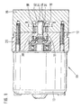
- FIG. 1 shows a Longitudinal section through a pump unit with a Gear pump
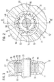
- Figures 2 and 3 cuts through the Gear pump along the line II-II in Figure 1 or III-III in Figure 2 on a larger scale than in Figure 1.
- a pump unit designated 10 has one Gear pump 11 in a two-part housing 12 and one electric drive motor 13 on ( Figure 1).
- the Gear pump 11 is of an externally toothed gear 14 and an internally toothed toothed ring 15 is formed.
- the gear pump 11 is of the type of the crescentless internal gear pump (Gerotor pump).
- Your toothed ring has a finite number Teeth 16 and one reduced by one tooth Number of teeth 17 of the gear 14.
- the gear 14 and the Toothed ring 15 are in a circular cylindrical recess 18 a first part 19 of the housing 12 facing away from the engine added.
- Against the drive motor 13 is the Recess 18 through a second part 20 of the housing 12 completed.
- the gear 14 is rotatably on one with the Drive motor 13 coupled pump shaft 21 arranged, which is guided in the housing 12.
- the gear 14 and the ring gear 15, which are together Comb, are, in relation to Figure 2, clockwise drivable, the gear ring being driven by the gear is set in rotation.
- the gear 14 and the gear ring 15 have axially offset axes 24 and 25, respectively.
- the Axis 24 of the gear 14 is also the axis of the Pump shaft 21, the axis 25 of the toothed ring 15 coincides with the Axis of the recess 18 together.
- the recess 18 is from a first side wall 26 of the housing part 19 axially limited ( Figure 3).
- the housing part 19 also forms one the toothed ring 15 radially leading jacket wall 27. Die Recess 18 is finally on their first Side wall 26 opposite side by one of the Housing part 20 formed second wall 28 limited.
- the first Side wall 26 and the second side wall 28 take over axial guidance of gear 14 and gear ring 15.
- Suction port 31 and a pressure port 32 for the Gear pump 11 hydraulic fluid to be pumped educated.
- the in the representation of Figure 2 before the Plane and therefore dash-dotted indicated openings 31 and 32 each have one kidney-shaped outline and are approximately concentric to the Axes 24 and 25 of gear 14 and gear ring 15.
- Die Suction opening 31 and the pressure opening 32 extend over each about 150 ° of the circumference of gear 14 and gear ring 15.
- the two openings 31 and 32 take in the circumferential direction a mutual distance from each other, which corresponds to at least one tooth pitch.
- the suction opening 31 and the pressure opening 32 change in the course of their course their radial latitude.
- the pressure opening 32 has, in Direction of rotation (clockwise) of gear 14 and gear ring 15 successively an entry zone 33, a central zone 34 and an outlet zone 35.
- the inlet zone 33 has one greater radial width than the central zone 34, and the Outlet zone 35 is narrower than central zone 34.
- the pressure opening 32 in fluid-carrying connection opposite a depression in the form of a Hollow cone 38.
- Its mouth is the recess 18 facing; the axis 39 of the hollow cone 38 runs parallel to the longitudinal axis 25 of the recess 18.
- the hollow cone 38 a cone angle of about 120 °.
- the mouth cross section (the diameter) of the with its wall to the Recess 18 adjacent hollow cone 38 is selected so that he at least from the full radial width of the toothed ring 15 is covered.
- the mouth cross section of the hollow cone 38 extends starting from the jacket wall 27 against the axis 25 to over the ring gear of the gear 14 ( Figure 2). It is also over Figure 2 shows that the mouth cross section of the Hollow cone 38 up to the radially inner boundary wall 40 reaches the pressure opening 32.
- the hollow cone 38 is the central zone 34 of the pressure opening 32 opposite in the side wall 28 of the housing part 20 arranged.
- gear pump 11 When the gear pump 11 is operating, this occurs from Gear 14 and gear ring 15 conveyed fluid to the pressure opening 32 and in the hollow cone 38. Due to the rotational movement of gear 14 and in particular gear ring 15, the fluid Discharged from the hollow cone 38 and forms a Gear and in particular the film bearing the gear ring the side wall 28. At the same time, fluid also gets into the gap between the casing of the toothed ring 15 and the casing wall 27 of the housing part 19. The fluid film forms a stable one Layer, so that the area of mixed friction when the Gear pump 11 run through quickly and during Pump operation is avoided. At the same time the Fluid film a base layer, which from the side of the Axial forces acting on the pressure ring 32 on the toothed ring 15 at least partially compensates.
- the Cone angle and its location in the recess 18 selected become.
- the cone angle in the Limits can be varied between 90 and 150 ° to influence the drag flow discharging the fluid from the hollow cone to take.
- the hollow cone 38 in the area of Inlet zone 33 of the pressure opening 32 are shifted. This will, based on the path of the Gear pump 11 conveyed fluid, one in the conveying direction earlier structure of the load-bearing fluid film under the toothed ring 15 scored.
Landscapes
- Engineering & Computer Science (AREA)
- Mechanical Engineering (AREA)
- General Engineering & Computer Science (AREA)
- Rotary Pumps (AREA)
Description
Claims (7)
- Zahnradpumpe (11) mit einem außenverzahnten Zahnrad (14) und einem innenverzahnten Zahnring (15), der in einer kreiszylindrischen Aussparung (18) eines Gehäuses (12) geführt ist und zusammen mit dem Zahnrad (14) um die jeweils eigene, aber gegeneinander versetzte Achse (24, 25) rotiert, sowie mit einer Saugöffnung (31) und einer nierenförmigen Drucköffnung (32) in einer ersten, die Aussparung (18) begrenzenden Seitenwand (26) des Gehäuses (12) und ferner mit einer der Drucköffnung (32) in fluidleitender Verbindung gegenüberliegenden Einsenkung (38) in einer die Aussparung (18) auf der anderen Seite begrenzenden zweiten Wand (28) des Gehäuses (12), dadurch gekennzeichnet, daß die Einsenkung als Hohlkegel (38) ausgebildet ist.
- Zahnradpumpe nach Anspruch 1, dadurch gekennzeichnet, daß der Hohlkegel (38) einen Kegelwinkel zwischen 90 und 150°, vorzugsweises 120° hat.
- Zahnradpumpe nach Anspruch 2, dadurch gekennzeichnet, daß der Hohlkegel (38) mit parallel zur Achse (25) der Aussparung (18) verlaufender Achse (39) angeordnet ist.
- Zahnradpumpe nach Anspruch 1, dadurch gekennzeichnet, daß der Mündungsquerschnitt des Hohlkegels (38) wenigstens von dem Zahnring (15) überstrichen ist.
- Zahnradpumpe nach Anspruch 1, dadurch gekennzeichnet, daß der Mündungsquerschnitt des Hohlkegels (38) von dem Zahnring (15) und wenigstens von den Zähnen (17) des Zahnrads (14) überstrichen ist.
- Zahnradpumpe nach Anspruch 1, dadurch gekennzeichnet, daß der Hohlkörper (38) in der Mittelzone (34) der Drucköffnung (32) angeordnet ist.
- Zahnradpumpe nach Anspruch 1, dadurch gekennzeichnet, daß der Hohlkegel (38) im Bereich der Einlaufzone (33) der Drucköffnung (32) angeordnet ist.
Applications Claiming Priority (3)
| Application Number | Priority Date | Filing Date | Title |
|---|---|---|---|
| DE19802137 | 1998-01-22 | ||
| DE19802137A DE19802137C1 (de) | 1998-01-22 | 1998-01-22 | Zahnradpumpe |
| PCT/DE1998/003135 WO1999037922A1 (de) | 1998-01-22 | 1998-10-27 | Zahnradpumpe |
Publications (2)
| Publication Number | Publication Date |
|---|---|
| EP1049876A1 EP1049876A1 (de) | 2000-11-08 |
| EP1049876B1 true EP1049876B1 (de) | 2002-07-24 |
Family
ID=7855233
Family Applications (1)
| Application Number | Title | Priority Date | Filing Date |
|---|---|---|---|
| EP98961048A Expired - Lifetime EP1049876B1 (de) | 1998-01-22 | 1998-10-27 | Zahnradpumpe |
Country Status (5)
| Country | Link |
|---|---|
| US (1) | US6280167B1 (de) |
| EP (1) | EP1049876B1 (de) |
| JP (1) | JP2002501147A (de) |
| DE (2) | DE19802137C1 (de) |
| WO (1) | WO1999037922A1 (de) |
Families Citing this family (10)
| Publication number | Priority date | Publication date | Assignee | Title |
|---|---|---|---|---|
| DE19814545A1 (de) * | 1998-04-01 | 1999-10-07 | Schwaebische Huettenwerke Gmbh | Ölpumpe mit Druckausgleichsbohrung |
| US6997689B2 (en) * | 2003-02-20 | 2006-02-14 | Honeywell International Inc. | Offset bearing for extended fuel pump life |
| JP2006329054A (ja) * | 2005-05-26 | 2006-12-07 | Hitachi Powdered Metals Co Ltd | トロコイドポンプ |
| US20130071280A1 (en) * | 2011-06-27 | 2013-03-21 | James Brent Klassen | Slurry Pump |
| CN103422981B (zh) * | 2012-05-21 | 2016-03-23 | 北京星旋世纪科技有限公司 | 星旋式流体机械及其应用的发动机和流体马达 |
| CN104769221B (zh) * | 2012-10-29 | 2019-06-04 | 皮尔伯格泵技术有限责任公司 | 机动车电液泵 |
| WO2014146190A1 (en) | 2013-03-21 | 2014-09-25 | James Klassen | Slurry pump |
| DE102014209685B3 (de) * | 2014-05-21 | 2015-10-22 | Sms Meer Gmbh | Strangpresse mit Hydraulikantrieb |
| JP6369194B2 (ja) * | 2014-07-23 | 2018-08-08 | 株式会社ジェイテクト | 電動ポンプユニット |
| US11067076B2 (en) | 2015-09-21 | 2021-07-20 | Genesis Advanced Technology Inc. | Fluid transfer device |
Family Cites Families (3)
| Publication number | Priority date | Publication date | Assignee | Title |
|---|---|---|---|---|
| US2872872A (en) * | 1954-11-23 | 1959-02-10 | Gerotor May Corp Of Maryland | Hydraulic pump or motor |
| US3834842A (en) * | 1971-12-06 | 1974-09-10 | Hydraulic Prod Inc | Hydraulic power translating device |
| JP2699390B2 (ja) * | 1988-03-28 | 1998-01-19 | アイシン精機株式会社 | 内接歯車モータ |
-
1998
- 1998-01-22 DE DE19802137A patent/DE19802137C1/de not_active Expired - Fee Related
- 1998-10-27 WO PCT/DE1998/003135 patent/WO1999037922A1/de not_active Ceased
- 1998-10-27 US US09/600,918 patent/US6280167B1/en not_active Expired - Lifetime
- 1998-10-27 JP JP2000528801A patent/JP2002501147A/ja active Pending
- 1998-10-27 EP EP98961048A patent/EP1049876B1/de not_active Expired - Lifetime
- 1998-10-27 DE DE59804939T patent/DE59804939D1/de not_active Expired - Lifetime
Also Published As
| Publication number | Publication date |
|---|---|
| EP1049876A1 (de) | 2000-11-08 |
| JP2002501147A (ja) | 2002-01-15 |
| DE19802137C1 (de) | 1999-03-04 |
| US6280167B1 (en) | 2001-08-28 |
| DE59804939D1 (de) | 2002-08-29 |
| WO1999037922A1 (de) | 1999-07-29 |
Similar Documents
| Publication | Publication Date | Title |
|---|---|---|
| EP0774077B2 (de) | Strömungspumpe zum fördern von kraftstoff aus einem vorratsbehälter zur brennkraftmaschine eines kraftfahrzeugs | |
| EP0362906B1 (de) | Innenzahnradpumpe | |
| DE3400594A1 (de) | Stroemungsmaschine | |
| DE4318122C2 (de) | Aggregat zum Fördern von Kraftstoff aus einem Vorratstank zur Brennkraftmaschine eines Kraftfahrzeugs | |
| DE19802137C1 (de) | Zahnradpumpe | |
| EP0786058B1 (de) | Automatgetriebe, insbesondere für kraftfahrzeuge | |
| EP0737812B1 (de) | Zahnradpumpe | |
| DE10296838B4 (de) | Zahnradpumpe | |
| EP1071885A1 (de) | Seitenkanalpumpe | |
| WO1997046809A1 (de) | Aggregat zum fördern von kraftstoff aus einem vorratsbehälter zur brennkraftmaschine eines kraftfahrzeugs | |
| EP3827170B1 (de) | Fluidfördereinrichtung | |
| DE102004014457B4 (de) | Kraftstoffpumpe | |
| EP1828609B1 (de) | Flügelzellenpumpe | |
| WO2006063917A1 (de) | Flügelzellenpumpe | |
| EP0328745B1 (de) | Innenzahnradmaschine | |
| DE2523298A1 (de) | Rotationsverdraengerpumpe bzw. -motor | |
| DE102012217484A1 (de) | Innenzahnradpumpe, insbesondere für eine hydraulische Fahrzeugbremsanlage | |
| DE2258737A1 (de) | Seitenkanalverdichter | |
| EP0475109B1 (de) | Innenzahnradpumpe für Hydraulikflüssigkeit | |
| DE19528181A1 (de) | Peripheralpumpe, insbesondere zum Fördern von Kraftstoff aus einem Vorratstank zur Brennkraftmaschine eines Kraftfahrzeuges | |
| EP0763659A2 (de) | Flügelzellenpumpe | |
| EP1276992A1 (de) | Zahnradpumpe, insbesondere für eine hochdruck-kraftstoffpumpe | |
| DE8911302U1 (de) | Aggregat zum Fördern von Kraftstoff aus dem Vorratstank eines Kraftfahrzeuges zu dessen Brennkraftmaschine | |
| WO2016180570A1 (de) | Verdrängerpumpe, verfahren zum betreiben einer verdrängerpumpe, lenksystem und getriebe | |
| DE3734926C2 (de) |
Legal Events
| Date | Code | Title | Description |
|---|---|---|---|
| PUAI | Public reference made under article 153(3) epc to a published international application that has entered the european phase |
Free format text: ORIGINAL CODE: 0009012 |
|
| 17P | Request for examination filed |
Effective date: 20000822 |
|
| AK | Designated contracting states |
Kind code of ref document: A1 Designated state(s): DE FR GB |
|
| GRAG | Despatch of communication of intention to grant |
Free format text: ORIGINAL CODE: EPIDOS AGRA |
|
| 17Q | First examination report despatched |
Effective date: 20011010 |
|
| GRAG | Despatch of communication of intention to grant |
Free format text: ORIGINAL CODE: EPIDOS AGRA |
|
| GRAH | Despatch of communication of intention to grant a patent |
Free format text: ORIGINAL CODE: EPIDOS IGRA |
|
| GRAH | Despatch of communication of intention to grant a patent |
Free format text: ORIGINAL CODE: EPIDOS IGRA |
|
| GRAA | (expected) grant |
Free format text: ORIGINAL CODE: 0009210 |
|
| AK | Designated contracting states |
Kind code of ref document: B1 Designated state(s): DE FR GB |
|
| REG | Reference to a national code |
Ref country code: GB Ref legal event code: FG4D Free format text: NOT ENGLISH |
|
| REF | Corresponds to: |
Ref document number: 59804939 Country of ref document: DE Date of ref document: 20020829 |
|
| GBT | Gb: translation of ep patent filed (gb section 77(6)(a)/1977) |
Effective date: 20021003 |
|
| ET | Fr: translation filed | ||
| PLBE | No opposition filed within time limit |
Free format text: ORIGINAL CODE: 0009261 |
|
| STAA | Information on the status of an ep patent application or granted ep patent |
Free format text: STATUS: NO OPPOSITION FILED WITHIN TIME LIMIT |
|
| 26N | No opposition filed |
Effective date: 20030425 |
|
| PGFP | Annual fee paid to national office [announced via postgrant information from national office to epo] |
Ref country code: GB Payment date: 20131022 Year of fee payment: 16 Ref country code: FR Payment date: 20131018 Year of fee payment: 16 |
|
| GBPC | Gb: european patent ceased through non-payment of renewal fee |
Effective date: 20141027 |
|
| PG25 | Lapsed in a contracting state [announced via postgrant information from national office to epo] |
Ref country code: GB Free format text: LAPSE BECAUSE OF NON-PAYMENT OF DUE FEES Effective date: 20141027 |
|
| REG | Reference to a national code |
Ref country code: FR Ref legal event code: ST Effective date: 20150630 |
|
| PG25 | Lapsed in a contracting state [announced via postgrant information from national office to epo] |
Ref country code: FR Free format text: LAPSE BECAUSE OF NON-PAYMENT OF DUE FEES Effective date: 20141031 |
|
| PGFP | Annual fee paid to national office [announced via postgrant information from national office to epo] |
Ref country code: DE Payment date: 20151215 Year of fee payment: 18 |
|
| REG | Reference to a national code |
Ref country code: DE Ref legal event code: R119 Ref document number: 59804939 Country of ref document: DE |
|
| PG25 | Lapsed in a contracting state [announced via postgrant information from national office to epo] |
Ref country code: DE Free format text: LAPSE BECAUSE OF NON-PAYMENT OF DUE FEES Effective date: 20170503 |