EP1048313A2 - Wegeventil - Google Patents
Wegeventil Download PDFInfo
- Publication number
- EP1048313A2 EP1048313A2 EP00104496A EP00104496A EP1048313A2 EP 1048313 A2 EP1048313 A2 EP 1048313A2 EP 00104496 A EP00104496 A EP 00104496A EP 00104496 A EP00104496 A EP 00104496A EP 1048313 A2 EP1048313 A2 EP 1048313A2
- Authority
- EP
- European Patent Office
- Prior art keywords
- valve body
- valve
- coil
- current
- directional valve
- Prior art date
- Legal status (The legal status is an assumption and is not a legal conclusion. Google has not performed a legal analysis and makes no representation as to the accuracy of the status listed.)
- Withdrawn
Links
Images

Classifications
-
- A—HUMAN NECESSITIES
- A61—MEDICAL OR VETERINARY SCIENCE; HYGIENE
- A61M—DEVICES FOR INTRODUCING MEDIA INTO, OR ONTO, THE BODY; DEVICES FOR TRANSDUCING BODY MEDIA OR FOR TAKING MEDIA FROM THE BODY; DEVICES FOR PRODUCING OR ENDING SLEEP OR STUPOR
- A61M16/00—Devices for influencing the respiratory system of patients by gas treatment, e.g. mouth-to-mouth respiration; Tracheal tubes
- A61M16/20—Valves specially adapted to medical respiratory devices
- A61M16/201—Controlled valves
- A61M16/202—Controlled valves electrically actuated
- A61M16/203—Proportional
- A61M16/204—Proportional used for inhalation control
-
- A—HUMAN NECESSITIES
- A61—MEDICAL OR VETERINARY SCIENCE; HYGIENE
- A61M—DEVICES FOR INTRODUCING MEDIA INTO, OR ONTO, THE BODY; DEVICES FOR TRANSDUCING BODY MEDIA OR FOR TAKING MEDIA FROM THE BODY; DEVICES FOR PRODUCING OR ENDING SLEEP OR STUPOR
- A61M16/00—Devices for influencing the respiratory system of patients by gas treatment, e.g. mouth-to-mouth respiration; Tracheal tubes
- A61M16/20—Valves specially adapted to medical respiratory devices
- A61M16/201—Controlled valves
- A61M16/202—Controlled valves electrically actuated
- A61M16/203—Proportional
- A61M16/205—Proportional used for exhalation control
-
- F—MECHANICAL ENGINEERING; LIGHTING; HEATING; WEAPONS; BLASTING
- F16—ENGINEERING ELEMENTS AND UNITS; GENERAL MEASURES FOR PRODUCING AND MAINTAINING EFFECTIVE FUNCTIONING OF MACHINES OR INSTALLATIONS; THERMAL INSULATION IN GENERAL
- F16K—VALVES; TAPS; COCKS; ACTUATING-FLOATS; DEVICES FOR VENTING OR AERATING
- F16K31/00—Actuating devices; Operating means; Releasing devices
- F16K31/02—Actuating devices; Operating means; Releasing devices electric; magnetic
- F16K31/06—Actuating devices; Operating means; Releasing devices electric; magnetic using a magnet, e.g. diaphragm valves, cutting off by means of a liquid
- F16K31/0675—Electromagnet aspects, e.g. electric supply therefor
-
- F—MECHANICAL ENGINEERING; LIGHTING; HEATING; WEAPONS; BLASTING
- F16—ENGINEERING ELEMENTS AND UNITS; GENERAL MEASURES FOR PRODUCING AND MAINTAINING EFFECTIVE FUNCTIONING OF MACHINES OR INSTALLATIONS; THERMAL INSULATION IN GENERAL
- F16K—VALVES; TAPS; COCKS; ACTUATING-FLOATS; DEVICES FOR VENTING OR AERATING
- F16K31/00—Actuating devices; Operating means; Releasing devices
- F16K31/02—Actuating devices; Operating means; Releasing devices electric; magnetic
- F16K31/06—Actuating devices; Operating means; Releasing devices electric; magnetic using a magnet, e.g. diaphragm valves, cutting off by means of a liquid
- F16K31/08—Actuating devices; Operating means; Releasing devices electric; magnetic using a magnet, e.g. diaphragm valves, cutting off by means of a liquid using a permanent magnet
- F16K31/082—Actuating devices; Operating means; Releasing devices electric; magnetic using a magnet, e.g. diaphragm valves, cutting off by means of a liquid using a permanent magnet using a electromagnet and a permanent magnet
-
- A—HUMAN NECESSITIES
- A61—MEDICAL OR VETERINARY SCIENCE; HYGIENE
- A61M—DEVICES FOR INTRODUCING MEDIA INTO, OR ONTO, THE BODY; DEVICES FOR TRANSDUCING BODY MEDIA OR FOR TAKING MEDIA FROM THE BODY; DEVICES FOR PRODUCING OR ENDING SLEEP OR STUPOR
- A61M16/00—Devices for influencing the respiratory system of patients by gas treatment, e.g. mouth-to-mouth respiration; Tracheal tubes
- A61M16/0003—Accessories therefor, e.g. sensors, vibrators, negative pressure
- A61M2016/0015—Accessories therefor, e.g. sensors, vibrators, negative pressure inhalation detectors
- A61M2016/0018—Accessories therefor, e.g. sensors, vibrators, negative pressure inhalation detectors electrical
- A61M2016/0021—Accessories therefor, e.g. sensors, vibrators, negative pressure inhalation detectors electrical with a proportional output signal, e.g. from a thermistor
-
- A—HUMAN NECESSITIES
- A61—MEDICAL OR VETERINARY SCIENCE; HYGIENE
- A61M—DEVICES FOR INTRODUCING MEDIA INTO, OR ONTO, THE BODY; DEVICES FOR TRANSDUCING BODY MEDIA OR FOR TAKING MEDIA FROM THE BODY; DEVICES FOR PRODUCING OR ENDING SLEEP OR STUPOR
- A61M16/00—Devices for influencing the respiratory system of patients by gas treatment, e.g. mouth-to-mouth respiration; Tracheal tubes
- A61M16/0003—Accessories therefor, e.g. sensors, vibrators, negative pressure
- A61M2016/0027—Accessories therefor, e.g. sensors, vibrators, negative pressure pressure meter
-
- A—HUMAN NECESSITIES
- A61—MEDICAL OR VETERINARY SCIENCE; HYGIENE
- A61M—DEVICES FOR INTRODUCING MEDIA INTO, OR ONTO, THE BODY; DEVICES FOR TRANSDUCING BODY MEDIA OR FOR TAKING MEDIA FROM THE BODY; DEVICES FOR PRODUCING OR ENDING SLEEP OR STUPOR
- A61M16/00—Devices for influencing the respiratory system of patients by gas treatment, e.g. mouth-to-mouth respiration; Tracheal tubes
- A61M16/0003—Accessories therefor, e.g. sensors, vibrators, negative pressure
- A61M2016/003—Accessories therefor, e.g. sensors, vibrators, negative pressure with a flowmeter
- A61M2016/0033—Accessories therefor, e.g. sensors, vibrators, negative pressure with a flowmeter electrical
- A61M2016/0039—Accessories therefor, e.g. sensors, vibrators, negative pressure with a flowmeter electrical in the inspiratory circuit
-
- A—HUMAN NECESSITIES
- A61—MEDICAL OR VETERINARY SCIENCE; HYGIENE
- A61M—DEVICES FOR INTRODUCING MEDIA INTO, OR ONTO, THE BODY; DEVICES FOR TRANSDUCING BODY MEDIA OR FOR TAKING MEDIA FROM THE BODY; DEVICES FOR PRODUCING OR ENDING SLEEP OR STUPOR
- A61M16/00—Devices for influencing the respiratory system of patients by gas treatment, e.g. mouth-to-mouth respiration; Tracheal tubes
- A61M16/0003—Accessories therefor, e.g. sensors, vibrators, negative pressure
- A61M2016/003—Accessories therefor, e.g. sensors, vibrators, negative pressure with a flowmeter
- A61M2016/0033—Accessories therefor, e.g. sensors, vibrators, negative pressure with a flowmeter electrical
- A61M2016/0042—Accessories therefor, e.g. sensors, vibrators, negative pressure with a flowmeter electrical in the expiratory circuit
Definitions
- the present invention relates to a directional valve according to the preamble to claim 1.
- Directional valves are used in respiratory devices, anaesthetic machines in particular, to channel the direction of flow.
- One directional valve is generally installed in the anaesthetic machine's inspiratory line and one directional valve in its expiratory line.
- the directional valves should not affect expiratory resistance and inspiratory resistance for the patient nor interfere with measurements of flow in the anaesthetic machine.
- One way to meet these conditions has been to devise directional valves with the lowest possible opening pressure. They are therefore generally devised as disk valves, i.e. the directional valve has a disk-shaped valve body that rests loosely on a valve seat.
- valve body If it is devised as a soft, lightweight disk, retrograde leakage could occur. Moreover, the valve body could be deformed enough by high back pressures to be pushed down into the valve opening. This would naturally be a serious development, since the directional valve would then stop working. Retrograde leakage can be reduced by the use of a heavier directional valve, but this would naturally increase the valve's opening pressure, and the valve body might then start wobbling. Stiff valve bodies (usually ceramic disks) could start to leak because of the deposition of calcium particles etc. on the valve seat.
- One object of the invention is to achieve a direction valve that solves the aforementioned problems.
- valve body contains a ferromagnetic material and two coils are arranged with one coil on top of the valve body and one coil underneath the valve body, the valve body can be made to press against the valve seat or alternately lift off the valve seat by regulating the current flowing through the respective coil.
- the directional valve can be operated as a servo system when the valve body contains a permanently magnetised material and a coil encircles the valve body and valve opening (to achieve the strongest possible magnetic coupling between the coil and the valve body).
- a current is applied across the coil, generating a magnetic field that presses the valve body harder against the valve seat. This would accordingly reduce the risk of leakage.
- the directional valve In the event of any loss of current, the directional valve would operate in the same way as in the prior art. Directional valve operation is not interrupted. This is an important safety feature when the valve is used in anaesthetic machines and other respiratory devices.
- Control unit could regulate the source of current in such a way that directional valve operation parallels the respiratory devices's inspiratory and expiratory phases.
- the directional valve in the inspiratory line would then be open during inspiration and closed during expiration (and the reverse for the directional valve in the expiratory line).
- this kind of simplified regulation is only possible in certain limited conditions, e.g. no bias flow is used and the patient is not breathing spontaneously.
- the control unit can therefore be devised to control the source of current by sensing the valve body's position. This can be achieved by inductive sensing of the coil. Alternately, the EMF generated by the valve body's movements can be sensed and employed for controlling the source of current. Any deformation of the valve body can even be sensed from changes in inductance.
- parameters can also be used for regulation.
- the pressure gradient between the inlet and outlet sides of the directional valve and flow through the directional valve can be obtained either by devising the directional valve with a pressure gauge or a flow meter or by utilising measurement signals from existing pressure gauges or flow meters in the respiratory device.
- FIG. 1 shows a respiratory device 2 connected to a patient 4, in the conventional, known fashion, by an inspiratory line 6, a patient line 8 and an expiratory line 10.
- the respiratory device 2 can e.g. consist of an anaesthetic machine, and the patient line 8 can consist of a tracheal tube and Y piece.
- a first directional valve 12 is arranged in the inspiratory line 6 (or between the inspiratory line 12 and the patient line 8), and a second directional valve 14 is arranged in the expiratory line 10 (or between the expiratory line 10 and the patient line 8).
- the function of the directional valves 12, 14 is mainly to achieve one-way passage of gas through the lines 6, 8, 10. So they must not allow any retrograde leakage. At the same time, it is undesirable for the directional valves 12, 14 to create any additional respiratory resistance for the patient 4 during inspiration and expiration. They must therefore open easily in the forward direction.
- FIG. 2 shows a first embodiment of the first directional valve 12 (the second has an identical construction).
- the inspiratory line 6 is connected to the inlet side of the first directional valve 12, and the patient line 8 is connected to the outlet side of the first directional valve 12.
- the first directional valve 12 has an essentially horizontal valve seat 16.
- a valve body 18 rests on the valve seat 16.
- the valve body 18 is disk-shaped, but other designs are possible.
- the surface of the valve body 18 in contact with the valve seat 16 should be made of a soft material.
- a hood 20 encircles the valve seat 16 and the valve body 18.
- the hood 20 is advantageously transparent to permit visual inspection by the operator.
- a coil 22 surrounds part of the first directional valve 12 for magnetic coupling to the valve body 18 that contains, or consists of, a permanently magnetised ferromagnetic material.
- the valve body 18 When a current is applied to the coil 22 from a source of current 24, the valve body 18 is either pressed against the valve seat 16 or lifted off the valve seat 16, depending on the direction of current in the coil.
- the directional valve's 12 basic functions can accordingly be enhanced without loss in the event of a power failure. This is extremely important to patient safety.
- the source of current 24 is regulated by a control unit 26 on the basis of suitable control parameters.
- Some of these control parameters can be obtained from changes in EMF, induction etc. in the coil 22 occurring when the valve body 18 is affected by gases in the lines 6, 8. Determination of these parameters can be performed by e.g. measuring voltage across the coil 22 with a voltmeter 28 and sending the measured value to the control unit 26. (Alternately or as a complement, current in the coil 22 can also be measured and the measured value sent to the control unit 26.)
- the control unit 26 in the depicted embodiment is integrated into the respiratory device 2 and controls a first source of current 24A for regulating the first directional valve 12 and a second source of current 24B for regulating the second directional valve 14.
- a separate control unit in the form of a microchip or the equivalent can be integrated into the respective directional valve 12, 14.
- Additional opportunities for obtaining control parameters are provided with a first flow meter 30 in the inspiratory line 6, a second flow meter 32 in the expiratory line 10, a first pressure gauge 34 in the inspiratory line 6, a second pressure gauge 36 in the patient line 8 and a third pressure gauge 38 in the expiratory line 10.
- Flow through the respective directional valve 12, 14 or the pressure gradient between the inlet and outlet sides of the respective directional valve 12, 14 can be determined and used by the control unit 26 for regulating the directional valves 12, 14.
- the flow meters and pressure gauges 30, 32, 34, 36, 38 can consist of components integrated into the directional valves 12, 14 or of components in the respiratory device 2 (or any combination thereof).
- Regulation is suitably performed in such a way that the control unit 26, via the sources of current 24 and with the aid of the parameters, regulates the directional valves 12, 14 by reinforcing their natural positions (open-closed) in every phase of the respiratory cycle.
- the control unit 26 can suitably be supplied even with information from the respiratory devices's control system on the respiratory cycles etc. Alternately, the control unit 26 can even be an integral part of the respiratory device's 2 control and regulatory system.
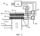
- FIG. 3 shows a second embodiment of the directional valve 12.
- the inspiratory line 6 is connected to the inlet side of the directional valve 12, and the patient line 8 is connected to the first directional valve's 12 outlet side.
- the first directional valve 12 has a mainly horizontal valve seat 16.
- a disk-shaped valve body 18 rests on the valve seat 16.
- the valve body 18 should be made of a soft material at points at which it is in contact with the valve seat 16.
- a hood 20 encircles the valve seat 16 and valve body 18.
- the hood 20 is advantageously transparent to permit visual inspection by the operator.
- the direction valve 12 contains a first coil 40, arranged below the valve body 18, and a second coil 42, arranged above the valve body 18.
- the valve body contains, or consists of, a ferromagnetic material.
- a current can be applied to the first coil 40 from a first source of current 44, and a current can be applied to the second coil 42 from a second source of current 46.
- the sources of current 44, 46 are regulated by a control unit 26 on the basis of suitable control parameters in the same way as in the first embodiment. These parameters can be obtained from a voltmeter 28, straight from the sources of current 44, 46 or in some other way described above. However, the sources of current 44, 46 are regulated differently, since current is alternately applied to the first coil 40 and the second coil 42 respectively.
- the directional valves ate possible.
- the coil(s) can be located in other ways with retention of the same functions.
Applications Claiming Priority (2)
| Application Number | Priority Date | Filing Date | Title |
|---|---|---|---|
| SE9901511A SE9901511D0 (sv) | 1999-04-27 | 1999-04-27 | Backventil för narkosapparat |
| SE9901511 | 1999-04-27 |
Publications (2)
| Publication Number | Publication Date |
|---|---|
| EP1048313A2 true EP1048313A2 (de) | 2000-11-02 |
| EP1048313A3 EP1048313A3 (de) | 2001-08-08 |
Family
ID=20415368
Family Applications (1)
| Application Number | Title | Priority Date | Filing Date |
|---|---|---|---|
| EP00104496A Withdrawn EP1048313A3 (de) | 1999-04-27 | 2000-03-07 | Wegeventil |
Country Status (4)
| Country | Link |
|---|---|
| US (1) | US6536433B1 (de) |
| EP (1) | EP1048313A3 (de) |
| JP (1) | JP2000354632A (de) |
| SE (1) | SE9901511D0 (de) |
Cited By (4)
| Publication number | Priority date | Publication date | Assignee | Title |
|---|---|---|---|---|
| WO2003058102A1 (en) | 2001-12-26 | 2003-07-17 | Arichell Technologies, Inc | Bathroom flushers with novel sensors and controllers |
| GB2521822A (en) * | 2013-11-26 | 2015-07-08 | Oes Medical Ltd | Valve Mechanism |
| GB2512401B (en) * | 2013-03-27 | 2015-10-14 | Carefusion Corp | Arrangement and method for guiding expired respiratory gas flow through a housing assembly for removing undesirable respiratory gas component and breathing |
| US9199050B2 (en) | 2012-04-30 | 2015-12-01 | Carefusion Corporation | Arrangement and method for guiding expired respiratory gas flow using gas routing device |
Families Citing this family (39)
| Publication number | Priority date | Publication date | Assignee | Title |
|---|---|---|---|---|
| US20190357827A1 (en) | 2003-08-01 | 2019-11-28 | Dexcom, Inc. | Analyte sensor |
| US8626257B2 (en) | 2003-08-01 | 2014-01-07 | Dexcom, Inc. | Analyte sensor |
| US7591801B2 (en) | 2004-02-26 | 2009-09-22 | Dexcom, Inc. | Integrated delivery device for continuous glucose sensor |
| US8886273B2 (en) | 2003-08-01 | 2014-11-11 | Dexcom, Inc. | Analyte sensor |
| US7920906B2 (en) | 2005-03-10 | 2011-04-05 | Dexcom, Inc. | System and methods for processing analyte sensor data for sensor calibration |
| US9247900B2 (en) | 2004-07-13 | 2016-02-02 | Dexcom, Inc. | Analyte sensor |
| US8615282B2 (en) | 2004-07-13 | 2013-12-24 | Dexcom, Inc. | Analyte sensor |
| US8425416B2 (en) | 2006-10-04 | 2013-04-23 | Dexcom, Inc. | Analyte sensor |
| US8532730B2 (en) | 2006-10-04 | 2013-09-10 | Dexcom, Inc. | Analyte sensor |
| US8425417B2 (en) | 2003-12-05 | 2013-04-23 | Dexcom, Inc. | Integrated device for continuous in vivo analyte detection and simultaneous control of an infusion device |
| US8423114B2 (en) | 2006-10-04 | 2013-04-16 | Dexcom, Inc. | Dual electrode system for a continuous analyte sensor |
| US8364231B2 (en) | 2006-10-04 | 2013-01-29 | Dexcom, Inc. | Analyte sensor |
| US8364230B2 (en) | 2006-10-04 | 2013-01-29 | Dexcom, Inc. | Analyte sensor |
| US11633133B2 (en) | 2003-12-05 | 2023-04-25 | Dexcom, Inc. | Dual electrode system for a continuous analyte sensor |
| US8287453B2 (en) * | 2003-12-05 | 2012-10-16 | Dexcom, Inc. | Analyte sensor |
| US8808228B2 (en) | 2004-02-26 | 2014-08-19 | Dexcom, Inc. | Integrated medicament delivery device for use with continuous analyte sensor |
| US7654956B2 (en) | 2004-07-13 | 2010-02-02 | Dexcom, Inc. | Transcutaneous analyte sensor |
| US7783333B2 (en) | 2004-07-13 | 2010-08-24 | Dexcom, Inc. | Transcutaneous medical device with variable stiffness |
| US8298142B2 (en) * | 2006-10-04 | 2012-10-30 | Dexcom, Inc. | Analyte sensor |
| US8275438B2 (en) | 2006-10-04 | 2012-09-25 | Dexcom, Inc. | Analyte sensor |
| US8478377B2 (en) | 2006-10-04 | 2013-07-02 | Dexcom, Inc. | Analyte sensor |
| US8449464B2 (en) | 2006-10-04 | 2013-05-28 | Dexcom, Inc. | Analyte sensor |
| US8562528B2 (en) | 2006-10-04 | 2013-10-22 | Dexcom, Inc. | Analyte sensor |
| US8447376B2 (en) | 2006-10-04 | 2013-05-21 | Dexcom, Inc. | Analyte sensor |
| EP2152350A4 (de) | 2007-06-08 | 2013-03-27 | Dexcom Inc | Integrierte medikamentenfreisetzungsvorrichtung mit kontinuierlichem analytsensor |
| EP4159114B1 (de) | 2007-10-09 | 2024-04-10 | DexCom, Inc. | Integriertes insulin-abgabesystem mit kontinuierlichem glucosesensor |
| US8396528B2 (en) | 2008-03-25 | 2013-03-12 | Dexcom, Inc. | Analyte sensor |
| US8251876B2 (en) | 2008-04-22 | 2012-08-28 | Hill-Rom Services, Inc. | Breathing exercise apparatus |
| WO2012142502A2 (en) | 2011-04-15 | 2012-10-18 | Dexcom Inc. | Advanced analyte sensor calibration and error detection |
| US9180271B2 (en) | 2012-03-05 | 2015-11-10 | Hill-Rom Services Pte. Ltd. | Respiratory therapy device having standard and oscillatory PEP with nebulizer |
| US9993604B2 (en) | 2012-04-27 | 2018-06-12 | Covidien Lp | Methods and systems for an optimized proportional assist ventilation |
| US10362967B2 (en) | 2012-07-09 | 2019-07-30 | Covidien Lp | Systems and methods for missed breath detection and indication |
| US9027552B2 (en) | 2012-07-31 | 2015-05-12 | Covidien Lp | Ventilator-initiated prompt or setting regarding detection of asynchrony during ventilation |
| US9950129B2 (en) | 2014-10-27 | 2018-04-24 | Covidien Lp | Ventilation triggering using change-point detection |
| JP6480598B2 (ja) | 2015-04-02 | 2019-03-13 | ヒル−ロム サービシーズ プライヴェート リミテッド | 呼吸装置用マニホールド |
| US11331022B2 (en) | 2017-10-24 | 2022-05-17 | Dexcom, Inc. | Pre-connected analyte sensors |
| CN209606445U (zh) | 2017-10-24 | 2019-11-08 | 德克斯康公司 | 预连接分析物传感器 |
| EP3628902B1 (de) * | 2018-09-28 | 2022-06-22 | Tecan Trading Ag | Verfahren zur steuerung eines magnetventils und verfahren zum dispensieren oder aspierieren eines flussigkeitsvolumens sowie entsprechende dispensier-/pipettier-vorrichtung |
| US11324954B2 (en) | 2019-06-28 | 2022-05-10 | Covidien Lp | Achieving smooth breathing by modified bilateral phrenic nerve pacing |
Citations (3)
| Publication number | Priority date | Publication date | Assignee | Title |
|---|---|---|---|---|
| US5127400A (en) * | 1990-03-23 | 1992-07-07 | Bird Products Corp. | Ventilator exhalation valve |
| EP0860175A2 (de) * | 1997-02-06 | 1998-08-26 | Instrumentarium Oy | Beatmungsgerät für verstärkte Beatmung sowie Ventil |
| EP0888796A1 (de) * | 1997-04-04 | 1999-01-07 | Siemens-Elema AB | Ventil |
Family Cites Families (14)
| Publication number | Priority date | Publication date | Assignee | Title |
|---|---|---|---|---|
| NL295251A (de) | 1963-10-15 | |||
| FR2185176A5 (de) | 1972-05-19 | 1973-12-28 | Vidalenq Maurice | |
| DE3231172C1 (de) | 1982-08-21 | 1984-03-01 | Drägerwerk AG, 2400 Lübeck | Elektromagnetisch betaetigtes Ventil fuer Druckmittel |
| US4506861A (en) | 1983-01-10 | 1985-03-26 | Automotive Engine Associates | Servo valve for ultra-fast pressure regulation with controlled system damping |
| CH655372A5 (fr) * | 1983-08-19 | 1986-04-15 | Honeywell Lucifer Sa | Valve electromagnetique. |
| DE3402118A1 (de) * | 1984-01-23 | 1985-07-25 | Robert Bosch Gmbh, 7000 Stuttgart | Steuerventil |
| DE3506180A1 (de) * | 1985-02-22 | 1986-08-28 | Festo KG, 7300 Esslingen | Kolben-zylinder-anordnung |
| US5678521A (en) * | 1993-05-06 | 1997-10-21 | Cummins Engine Company, Inc. | System and methods for electronic control of an accumulator fuel system |
| DK142593D0 (da) * | 1993-12-21 | 1993-12-21 | Ole Cramer Nielsen | Apparat til styring af en ventil |
| US5722632A (en) * | 1995-04-20 | 1998-03-03 | Borg-Warner Automotive, Inc. | Temperature-compensated exhaust gas recirculation system |
| US5628296A (en) * | 1996-01-16 | 1997-05-13 | Borg-Warner Automotive, Inc. | Temperature-compensated exhaust gas recirculation system |
| JP3842870B2 (ja) * | 1997-07-11 | 2006-11-08 | Smc株式会社 | 開閉弁 |
| GB2327742B (en) * | 1997-07-25 | 2001-12-12 | Denso Corp | Flow control valve |
| SE9801074D0 (sv) * | 1998-03-27 | 1998-03-27 | Siemens Elema Ab | Dosing device |
-
1999
- 1999-04-27 SE SE9901511A patent/SE9901511D0/xx unknown
-
2000
- 2000-03-07 EP EP00104496A patent/EP1048313A3/de not_active Withdrawn
- 2000-04-14 US US09/550,114 patent/US6536433B1/en not_active Expired - Lifetime
- 2000-04-25 JP JP2000124628A patent/JP2000354632A/ja active Pending
Patent Citations (3)
| Publication number | Priority date | Publication date | Assignee | Title |
|---|---|---|---|---|
| US5127400A (en) * | 1990-03-23 | 1992-07-07 | Bird Products Corp. | Ventilator exhalation valve |
| EP0860175A2 (de) * | 1997-02-06 | 1998-08-26 | Instrumentarium Oy | Beatmungsgerät für verstärkte Beatmung sowie Ventil |
| EP0888796A1 (de) * | 1997-04-04 | 1999-01-07 | Siemens-Elema AB | Ventil |
Cited By (6)
| Publication number | Priority date | Publication date | Assignee | Title |
|---|---|---|---|---|
| WO2003058102A1 (en) | 2001-12-26 | 2003-07-17 | Arichell Technologies, Inc | Bathroom flushers with novel sensors and controllers |
| EP1466118A1 (de) * | 2001-12-26 | 2004-10-13 | Arichell Technologies, Inc. | Badezimmerspülvorrichtungen mit neuen sensoren und steuerungen |
| EP1466118A4 (de) * | 2001-12-26 | 2008-11-12 | Arichell Tech Inc | Badezimmerspülvorrichtungen mit neuen sensoren und steuerungen |
| US9199050B2 (en) | 2012-04-30 | 2015-12-01 | Carefusion Corporation | Arrangement and method for guiding expired respiratory gas flow using gas routing device |
| GB2512401B (en) * | 2013-03-27 | 2015-10-14 | Carefusion Corp | Arrangement and method for guiding expired respiratory gas flow through a housing assembly for removing undesirable respiratory gas component and breathing |
| GB2521822A (en) * | 2013-11-26 | 2015-07-08 | Oes Medical Ltd | Valve Mechanism |
Also Published As
| Publication number | Publication date |
|---|---|
| SE9901511D0 (sv) | 1999-04-27 |
| US6536433B1 (en) | 2003-03-25 |
| EP1048313A3 (de) | 2001-08-08 |
| JP2000354632A (ja) | 2000-12-26 |
Similar Documents
| Publication | Publication Date | Title |
|---|---|---|
| EP1048313A2 (de) | Wegeventil | |
| JP4336823B2 (ja) | 患者用ベンチレータのための呼気バルブ | |
| US7565906B2 (en) | Pressure/flow control valve and system using same | |
| US6269839B1 (en) | Control member for a valve and method for determining fluid flow rate through a valve | |
| US7969146B2 (en) | Displacement measurement device | |
| DE69533597D1 (de) | Ausatmungsventil mit Messwertaufnehmer für die Ausatmungsströmung | |
| JP2002501614A (ja) | 医療用ガス流量計およびモニター | |
| EP1273317B1 (de) | Flüssigkeitsströmungsreguliersystem | |
| US3039481A (en) | Magnetic control for respirator valve | |
| US5606236A (en) | Two wire position sense and control of modulating gas valve or other electromechanical actuators | |
| US20040007232A1 (en) | Method of regulating the open-loop pressure of a repiratory assistance apparatus | |
| GB2286871B (en) | Butterfly valve | |
| DE60031645D1 (de) | Ventil zur Regelung und Messung der Strömungsgschwindigkeit eines Fluids | |
| RU2654014C2 (ru) | Линейный цифровой пропорциональный пьезоэлектрический клапан | |
| JP4994838B2 (ja) | 制御装置によって油圧を測定する方法及び装置 | |
| US6729343B2 (en) | Valve arrangement for controlling the flow rate of a gas | |
| JP2000205447A (ja) | 開度表示機能付き逆止弁 | |
| US20210220545A1 (en) | Non-contacting, high accuracy pressure sensing for medical cassette assemblies | |
| JPS62245920A (ja) | 流量調節機能を有する流量検出器 | |
| JP2921976B2 (ja) | 人工呼吸器における呼気弁装置 | |
| CN104208788A (zh) | 呼吸面罩和具有该呼吸面罩的呼吸机 | |
| JPH0257773A (ja) | リフトセンサ付電磁弁 | |
| JPS6214818Y2 (de) | ||
| JP4584473B2 (ja) | 呼吸用気体供給装置 | |
| SU1170655A1 (ru) | Способ определени объема легких и устройство дл его осуществлени (его варианты) |
Legal Events
| Date | Code | Title | Description |
|---|---|---|---|
| PUAI | Public reference made under article 153(3) epc to a published international application that has entered the european phase |
Free format text: ORIGINAL CODE: 0009012 |
|
| AK | Designated contracting states |
Kind code of ref document: A2 Designated state(s): DE FR |
|
| AX | Request for extension of the european patent |
Free format text: AL;LT;LV;MK;RO;SI |
|
| PUAL | Search report despatched |
Free format text: ORIGINAL CODE: 0009013 |
|
| AK | Designated contracting states |
Kind code of ref document: A3 Designated state(s): AT BE CH CY DE DK ES FI FR GB GR IE IT LI LU MC NL PT SE |
|
| AX | Request for extension of the european patent |
Free format text: AL;LT;LV;MK;RO;SI |
|
| RIC1 | Information provided on ipc code assigned before grant |
Free format text: 7A 61M 16/20 A, 7F 16K 31/06 B, 7F 16K 15/00 B, 7F 16K 15/02 B |
|
| 17P | Request for examination filed |
Effective date: 20011203 |
|
| AKX | Designation fees paid |
Free format text: DE FR |
|
| RAP1 | Party data changed (applicant data changed or rights of an application transferred) |
Owner name: MAQUET CRITICAL CARE AB |
|
| 17Q | First examination report despatched |
Effective date: 20040309 |
|
| STAA | Information on the status of an ep patent application or granted ep patent |
Free format text: STATUS: THE APPLICATION IS DEEMED TO BE WITHDRAWN |
|
| 18D | Application deemed to be withdrawn |
Effective date: 20040921 |