EP1048255A1 - Liquid heating vessels - Google Patents
Liquid heating vessels Download PDFInfo
- Publication number
- EP1048255A1 EP1048255A1 EP00115449A EP00115449A EP1048255A1 EP 1048255 A1 EP1048255 A1 EP 1048255A1 EP 00115449 A EP00115449 A EP 00115449A EP 00115449 A EP00115449 A EP 00115449A EP 1048255 A1 EP1048255 A1 EP 1048255A1
- Authority
- EP
- European Patent Office
- Prior art keywords
- vessel
- wall
- plate
- channel
- base
- Prior art date
- Legal status (The legal status is an assumption and is not a legal conclusion. Google has not performed a legal analysis and makes no representation as to the accuracy of the status listed.)
- Granted
Links
- 238000010438 heat treatment Methods 0.000 title claims abstract description 45
- 239000007788 liquid Substances 0.000 title claims abstract description 22
- 230000002093 peripheral effect Effects 0.000 claims abstract description 21
- 239000004033 plastic Substances 0.000 claims abstract description 21
- 229920003023 plastic Polymers 0.000 claims abstract description 21
- 238000007789 sealing Methods 0.000 claims abstract description 17
- 239000011324 bead Substances 0.000 claims abstract description 5
- 229920002379 silicone rubber Polymers 0.000 claims abstract description 4
- 239000004945 silicone rubber Substances 0.000 claims abstract description 4
- 239000000463 material Substances 0.000 claims description 21
- 239000000758 substrate Substances 0.000 claims description 11
- PXHVJJICTQNCMI-UHFFFAOYSA-N Nickel Chemical compound [Ni] PXHVJJICTQNCMI-UHFFFAOYSA-N 0.000 claims description 10
- 230000003647 oxidation Effects 0.000 claims description 9
- 238000007254 oxidation reaction Methods 0.000 claims description 9
- 229910052759 nickel Inorganic materials 0.000 claims description 5
- 238000005485 electric heating Methods 0.000 claims description 4
- 238000009792 diffusion process Methods 0.000 claims description 3
- 239000010935 stainless steel Substances 0.000 abstract description 8
- 229910001220 stainless steel Inorganic materials 0.000 abstract description 8
- 230000008901 benefit Effects 0.000 description 9
- 238000004519 manufacturing process Methods 0.000 description 5
- 238000013021 overheating Methods 0.000 description 4
- 238000007639 printing Methods 0.000 description 4
- 229910000990 Ni alloy Inorganic materials 0.000 description 3
- 239000002241 glass-ceramic Substances 0.000 description 3
- 238000009413 insulation Methods 0.000 description 3
- 229910052751 metal Inorganic materials 0.000 description 3
- 239000002184 metal Substances 0.000 description 3
- XLYOFNOQVPJJNP-UHFFFAOYSA-N water Substances O XLYOFNOQVPJJNP-UHFFFAOYSA-N 0.000 description 3
- 239000004743 Polypropylene Substances 0.000 description 2
- 238000009835 boiling Methods 0.000 description 2
- 239000000919 ceramic Substances 0.000 description 2
- 230000006835 compression Effects 0.000 description 2
- 238000007906 compression Methods 0.000 description 2
- 230000008021 deposition Effects 0.000 description 2
- 238000010304 firing Methods 0.000 description 2
- 239000011521 glass Substances 0.000 description 2
- -1 polypropylene Polymers 0.000 description 2
- 229920001155 polypropylene Polymers 0.000 description 2
- 238000005728 strengthening Methods 0.000 description 2
- 239000004411 aluminium Substances 0.000 description 1
- 229910052782 aluminium Inorganic materials 0.000 description 1
- XAGFODPZIPBFFR-UHFFFAOYSA-N aluminium Chemical compound [Al] XAGFODPZIPBFFR-UHFFFAOYSA-N 0.000 description 1
- 238000009411 base construction Methods 0.000 description 1
- 230000015572 biosynthetic process Effects 0.000 description 1
- 238000005524 ceramic coating Methods 0.000 description 1
- 238000000576 coating method Methods 0.000 description 1
- 238000010276 construction Methods 0.000 description 1
- 230000007797 corrosion Effects 0.000 description 1
- 238000005260 corrosion Methods 0.000 description 1
- 230000000694 effects Effects 0.000 description 1
- 229920001971 elastomer Polymers 0.000 description 1
- 238000010285 flame spraying Methods 0.000 description 1
- 238000005755 formation reaction Methods 0.000 description 1
- 238000007654 immersion Methods 0.000 description 1
- 239000011810 insulating material Substances 0.000 description 1
- 239000000314 lubricant Substances 0.000 description 1
- 238000000034 method Methods 0.000 description 1
- 238000012986 modification Methods 0.000 description 1
- 230000004048 modification Effects 0.000 description 1
- 230000001681 protective effect Effects 0.000 description 1
- 238000007650 screen-printing Methods 0.000 description 1
- 229910052709 silver Inorganic materials 0.000 description 1
- 239000004332 silver Substances 0.000 description 1
- 238000012360 testing method Methods 0.000 description 1
- 238000012546 transfer Methods 0.000 description 1
Images


Classifications
-
- A—HUMAN NECESSITIES
- A47—FURNITURE; DOMESTIC ARTICLES OR APPLIANCES; COFFEE MILLS; SPICE MILLS; SUCTION CLEANERS IN GENERAL
- A47J—KITCHEN EQUIPMENT; COFFEE MILLS; SPICE MILLS; APPARATUS FOR MAKING BEVERAGES
- A47J27/00—Cooking-vessels
- A47J27/21—Water-boiling vessels, e.g. kettles
- A47J27/21008—Water-boiling vessels, e.g. kettles electrically heated
- A47J27/21041—Water-boiling vessels, e.g. kettles electrically heated with heating elements arranged outside the water vessel
-
- H—ELECTRICITY
- H05—ELECTRIC TECHNIQUES NOT OTHERWISE PROVIDED FOR
- H05B—ELECTRIC HEATING; ELECTRIC LIGHT SOURCES NOT OTHERWISE PROVIDED FOR; CIRCUIT ARRANGEMENTS FOR ELECTRIC LIGHT SOURCES, IN GENERAL
- H05B3/00—Ohmic-resistance heating
- H05B3/20—Heating elements having extended surface area substantially in a two-dimensional plane, e.g. plate-heater
- H05B3/22—Heating elements having extended surface area substantially in a two-dimensional plane, e.g. plate-heater non-flexible
- H05B3/26—Heating elements having extended surface area substantially in a two-dimensional plane, e.g. plate-heater non-flexible heating conductor mounted on insulating base
- H05B3/265—Heating elements having extended surface area substantially in a two-dimensional plane, e.g. plate-heater non-flexible heating conductor mounted on insulating base the insulating base being an inorganic material, e.g. ceramic
-
- H—ELECTRICITY
- H05—ELECTRIC TECHNIQUES NOT OTHERWISE PROVIDED FOR
- H05B—ELECTRIC HEATING; ELECTRIC LIGHT SOURCES NOT OTHERWISE PROVIDED FOR; CIRCUIT ARRANGEMENTS FOR ELECTRIC LIGHT SOURCES, IN GENERAL
- H05B3/00—Ohmic-resistance heating
- H05B3/78—Heating arrangements specially adapted for immersion heating
- H05B3/82—Fixedly-mounted immersion heaters
Definitions
- the present invention relates to liquid heating vessels, and in particular to liquid heating vessels in which an electric heating element is mounted to or provided on the underside of a metallic vessel base.
- the present invention seeks to overcome this problem, and from a first aspect provides a liquid heating vessel comprising a plastics wall and a heated metallic plate forming at least a part of the base of said vessel, said plate having a peripheral channel grippingly receiving a depending portion of the vessel wall, and sealing means arranged and clamped between a wall of said channel and said depending portion of the vessel wall.
- the invention also extends to a metallic plate forming or for forming at least a part of the base of a liquid heating vessel comprising an upwardly open peripheral channel to receive a depending edge of a wall of said vessel.
- the depending portion of the vessel wall is clamped between the respective side faces of the channel, so as to compress the plastics material, preventing thermal tensile creep.
- the sealing means acts not only to provide a water-tight seal between the base and the vessel wall, but also acts to further thermally insulate the plastics material of the vessel wall from the base and to provide a resilient clamping force on the vessel wall.
- the plastics vessel wall may be the side wall of the vessel in which case the channel may engage over the lower edge of the wall.
- the outer wall may also extend inwardly to constitute part of the base of the vessel as well.
- a lip or the like may depend from the radially inner-periphery portion of the base portion of the vessel wall for engagement with the channel of the metallic plate.
- the metallic plate is of a relatively low thermal conductivity and, most preferably is of stainless steel.
- This has the advantage of reducing thermal conduction radially outwardly through the base, thereby avoiding overheating, and thus damage to, the lower part of the plastics wall. This is very important, in a dry switch on or boil dry situation, since a plastics material such as polypropylene, which may be used for the vessel wall, will melt at about 140°C, while the element may reach a temperature several hundred degrees higher.
- one or more circumferential grooves or other formations which locally reduce the plate thickness may be provided in the base between the element and the wall. This reduces the cross-sectional area of the base through which heat may flow radially, effectively 'choking' the flow of heat radially outwardly from the element.
- the invention provides a liquid heating vessel comprising a plastics wall portion, a metallic plate having an electric heating element on the underside thereof the plate being mounted, at its periphery, to said plastics wall portion, means being provided on the plate between the element and the vessel wall to restrict the flow of heat from the element to the vessel wall.
- the radially outer lower edge of the depending portion plastics wall may have a bead, around which the outer limb of the plate channel can be rolled or crimped to mount the base plate in position.
- the lower wall part may also be formed with means, such as a shoulder, to locate the sealing means and to prevent it being extruded out of the channel during assembly.
- the sealing means may comprise a sealing ring, for example of silicone rubber. This material is particularly preferred since typically it is stable up to temperatures of 250°C and will therefore be resistant to overheating of the metallic base should that occur.
- the seal may be rectangular in section, similar to a rubber band, so as more easily to locate in the channel.
- the seal has a diameter which is less than the internal diameter of the channel and is stretched as it engages in the channel. It has been found particularly advantageous in this respect if the cross sectional dimension of the seal in a direction along the base is greater than that in a direction perpendicular to the base, i.e. if the seal is wider in section than it is deep.
- a ring may have a an internal diameter of say 110mm, an external diameter of 120mm and a thickness of 1.0mm and may engage in a channel with an internal diameter of 125mm.
- the peripheral channel may have a continuous outer wall for engagement with the vessel wall.
- the outer wall of the channel is formed with a series of axially extending slots so as to defined a plurality of tabs for engagement with the vessel wall.
- the tabs may be formed so as to clip over the lower portion of the vessel wall during assembly, or to engage the vessel wall loosely and then be rolled or crimped onto the wall.
- the base plate of the vessel is heated by a heating element mounted or provided thereon.
- the element may for example be a metal sheathed heating element which is mounted directly to the plate or to a diffusion member attached to the plate.
- the element may also be a so-called printed heating element mounted on or applied to the plate.
- Such elements typically comprise a resistive heating track laid down (for example by printing or flame spraying) on an insulating glass, ceramic or glass ceramic substrate itself provided on the plate.
- the insulating substrate is first laid down on the base in a number of printing and firing operations, and the resistive track then typically, silk screen printed on the layer and fired.
- the plate has a surface portion radially inwardly of the channel for receiving a heating element and which projects beyond the base of the channel. This allows access to the surface for printing the element without interference from the peripheral channel.
- the radially inner wall of the channel may be joined to the projecting surface portion by an inwardly sloping wall, so that the inner portion of the base resembles a dish.
- This arrangement not only acts to strengthen the base (which means that a thinner gauge of base material may be used) but also increases the length of the thermal path to the vessel wall.
- the surface portion may be joined to the channel portion by a wall extending substantially parallel to the axis of the base. In such a case, the projecting surface portion may project by a greater amount below the channel base, so as to provide a longer thermal path to the channel.
- the thickness of the base plate material used may be reduced by providing peripheral strengthening.
- the plate thickness is usually of the order of 1.5 mm.
- the plate has to be that thick in order to resist buckling forces induced during operation by the different coefficients of expansion of the plate and the insulation layer.
- the plate thickness may be reduced to less than 1 mm.
- the invention provides a plate heater comprising a metallic plate having an electrically insulating substrate provided on a surface thereof and an electrical resistive heating track laid down on said substrate, wherein said plate is provided with stiffening means around its periphery and is less than 1 mm thick.
- the plate is between 0.4 and 0.6 mm and most preferably about 0.5 mm thick.
- the stiffening means may comprises a lip raised around the edge of the plate.
- the stiffening means provides a peripheral surface which can make a compression seal with a wall portion of a heating vessel to which it is mounted.
- the surface may be formed as part of a channel locating over a depending wall of the vessel.
- the reduction in thickness of the plate material also has the advantage that the heat transfer through the plate to the liquid in a vessel is improved. This has the effect that the temperature of the track itself is reduced in normal operation, as heat will be more efficiently conducted away from it to the liquid. Indeed with S430 stainless steel having a 0.1 mm thick insulating layer, with an element watts density of 70 Wcm -2 it has been calculated that when the liquid in the vessel boils, with a plate thickness of 1.5 mm, the temperature drop through the plate and layer from the element is about 80°C. With a thickness of 0.5 mm, however, that is reduced to about 55°C. Accordingly, when liquid in the vessel is boiling at 100°C, the track temperature with the thinner plate material will be 150°C as opposed to 180°C, a very significant reduction.
- the reduction in track temperature can be put to good advantage in a number of ways. Firstly, it is possible, for a given maximum permissible track temperature, to increase the watts density of the element, and thus decrease its size and diameter. This represents a cost saving in that a smaller amount of relatively expensive plate material and insulating materials may be used. Furthermore, the smaller the plate diameter the stronger it will be, so that a further reduction in thickness may be possible.
- the track is preferably generally spiral in shape or has one or more spiral portions, since this will allow a large number of turns of element track to be accommodated without regions of low radius which would act to provide current concentrations and thus local overheating.
- the invention provides a plater heater comprising a metallic plate having an electrically insulating substrate provided on a surface thereof and an electrical resistive heating track laid down on said substrate, said plate being less than 1 mm thick and said track being generally spiral in form.
- the turns of the spiral are less than 1 mm apart. This is made possible because the potential drop between adjacent turns is relatively low.
- This aspect of the invention is not limited to the use of circular spiral tracks, and the track could have a rectangular, triangular or other polygonal or curved spiral shape.
- the track could have a rectangular, triangular or other polygonal or curved spiral shape.
- a rectangular spiral would be appropriate.
- the invention is not limited to circular plates, but to any desired shape of plate.
- a further advantage of the lower track temperature is that it permits the use of track materials which are resistant to oxidation at lower temperatures and which can therefore dispense with the overglaze which is normally provided to protect the track material from oxidation.
- the invention provides a plate heater comprising a metallic plate having an electrically insulating substrate provided on a surface thereof and an electrical resistive heating track laid down on said substrate, the heater track being substantially exposed and of a material which is resistant to oxidation.
- track materials would be nickel or high nickel alloys which are resistant to oxidation at temperatures below at least 25°C. Furthermore, if the track material has a sufficiently low resistance, then it would be possible to use the track material itself to make electrical contact with a supply rather than have low-resistance contact pads as are usually provided.
- the preferred track material is nickel since it is inexpensive, has a positive temperature coefficient of resistance (which means that it will to some extent limit overheating in the event of the vessel boiling dry or being switched on dry) and is highly resistant to oxidation.
- the invention seeks to overcome this problem by providing an electrically heated base in or for a liquid heating vessel which is electrically insulated on its liquid-facing side.
- the insulation is provided by a fired glass, ceramic or glass ceramic coating.
- a fired glass, ceramic or glass ceramic coating are well known in the art as being used to insulate resistive heating tracks on the under-side of the base.
- the thickness and porosity of the insulating layer should be sufficient to provide satisfactory insulation during operation. Typically the thickness may be at least 1mm and the porosity and thickness sufficient to resist a flash test of over 2500 V.
- a water heating vessel 2 has a body 4 which is moulded from polypropylene, so as to have a wall 6 and a handle 8.
- the base 10 of the vessel 2 is smooth and is made of 0.4 to 0.6mm thick stainless steel plate. It is circular and has an electric heating element 12 and thermally sensitive control 14 mounted to its underside.
- the element 12 is mounted within an aluminium carrier which is attached to the underside of the base 10.
- the base 10 is also formed with a peripheral U-shaped channel 16. The initial shape of the outer limb 18 of the channel 16 is shown in dotted lines in Fig 2.
- a series of three concentric grooves 20 is formed in the underside of the base 10 between the element 12 and the channel 16. Each groove 20 is about 0.2 to 0.3mm deep and about 0.4 to 0.5 mm wide.
- the channel 16 receives the lower end portion 22 of the plastics wall 6.
- the radially inner wall 24 of the lower end portion 22 is formed with a shoulder 26 which acts to locate a rectangular section silicone rubber sealing ring 28.
- the radially outer wall 30 of the lower end portion 22 is formed with a bead 32 over which the outer limb 18 of the channel 16 may be rolled, as shown in Fig 2.
- the lower end portion 22 of the wall 6 is itself stepped inwardly, so as to allow a base cover 34 to lie flush with the wall 6.
- the vessel base is assembled as follows. Firstly, the sealing ring 28 is stretched over the lower end portion 22 of the wall 6, and located against the shoulder 26. A lubricant is then applied over the inner and outer walls of the lower end portion 22 and channel 16 of the base 10 pushed over the end portion 22, until the base 36 of the channel 16 abuts on the lower edge 38 of the wall 6. The seal 28 is prevented from being pushed into the vessel by the shoulder 26. When the base is in position, the outer limb 18 of the channel 16 is then rolled over the bead 32 to clamp the lower end portion 22 of the wall between it and the seal 28. This exerts a compressive force on the thickness of the wall 6, thereby minimising thermal creep.
- the lower end portion 22 of the wall 6 is also insulated thermally from the element 12 by the base 10 itself which is of stainless steel which has a relatively low thermal conductivity, by the grooves 20 which impede the flow of heat radially outwardly from the element, and by the sealing ring 28.
- a potential problem may arise with the base construction as shown in Figs. 1 and 2 when the heating means provided on the base comprises a printed heating element.
- the heating means provided on the base comprises a printed heating element.
- the peripheral channel 16 may get in the way.
- the modified base 36 shown in Fig. 3 overcomes this problem by having its central surface portion 38 offset from the base of the peripheral mounting channel 40 so as to project by a distance D therebelow.
- the offset D need not be large, for example it need only be in the region of 0.5mm.
- the central surface portion is connected with the upper end of the inner channel wall 42 by a sloping portion 44. This acts both to strengthen the base and also to increase the length of the thermal path to the wall of the vessel.
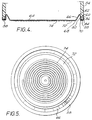
- Figs 4 and 5 show a base 50 of the type described in Fig. 3 printed with a heating track 52 and installed on the base of a liquid heating vessel 54.
- the base 50 comprises a stainless steel plate 56, 0.5 mm thick which is formed with a peripheral channel 58 for engagement over the lower end 60 of the plastics wall 62 of the vessel.
- the central region 64 of the plate 56 is joined to the channel 58 by an inclined section 66 which strengthens the central region 64 of the plate against buckling forces it will experience in use.
- the lower surface 68 of the central region 64 offset below the bottom surface 70 of the channel 58, by, for example a distance of 0.1 to 0.5 mm.
- the lower surface 68 is provided with an insulating layer 72 of glass ceramic approximately 0.1mm thick, laid down by any suitable technique, for example by printing and firing.
- the offset of the lower surface 68 from the channel base 70 allows clear access to the surface for that purpose.
- a spiral heating track 74 On top of the insulating layer 72 is laid down a spiral heating track 74.
- the track 74 is preferably laid down by silk screen printing which again is facilitated by the offset of the surface 68 from the claimed base 70.
- the track 74 is approximately 2.5 mm wide and the turns of the track are separated by a distance of about 0.5 to 1 mm. A gap of 4 mm to the outside of the insulating layer 72 is required to meet safety standards. A spiral pattern means that a greater length of track may be accommodated on a smaller diameter substrate, thereby reducing the size of the heater.
- the track material is nickel or a high nickel alloy which is resistant to oxidation at the normal working temperatures of the track, that is usually less than 250°C. Being resistant to oxidation, the track does not need a protective overglaze as is usually provided in such heaters, thereby reducing the number of production steps and thus cost. Furthermore, nickel and high nickel alloys have a sufficient low resistance to allow an electrical contact to be made directly to the track 74 rather than providing a separate low resistivity contact pad of, for example silver. Thus again reducing production costs.
- the plate 64 is mounted to the lower edge of the vessel wall 62 in the same manner as in the previous embodiment, with a compression seal 30 being arranged between the inner channel wall 82 and the vessel wall 62.
- the outer channel wall 84 is deformed into a recess 86 in the vessel 62 wall to retain the plate in position.
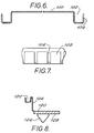
- a circular base 100 has a peripheral channel 102 for engaging the lower edge of the plastics vessel wall, as in the earlier embodiments described above.
- the outer wall 104 of the channel 102 is formed with a series of equispaced axially extending slots 106 so as to define a series of tabs 108 equispaced around the periphery of the channel 102.
- the slots 106 may be 1mm wide and the tabs 108 4mm wide.
- the base 100 may be assembled to the lower edge of the vessel wall, in the same way as described earlier, the tabs 108 being rolled over the bottom edge of the vessel wall. However, the tabs 108 will allow the base more easily to be removed from the vessel wall, for example if repair is required.
- the base 50 may then be re-mounted on the vessel wall in the same way as mentioned above, or, if the tabs have deflected resiliently inwardly to a diameter smaller than the outer diameter of the cooperating part of the vessel wall, by being snap-fitted onto that part of the vessel wall.
- Fig. 8 shows a modified version of a heater in accordance with the invention, with a central portion of the base being offset from the peripheral channel 120 by a portion 124 extending generally parallel to the axis of the base. This acts to increase the length of the thermal path to the peripheral channel 122 from the element 126 (shown in this embodiment as being mounted to a diffusion plate 128 mounted to the vessel base in a conventional manner), while at the same time allowing the diameter of the base to be reduced.
- the plate heaters have been fitted to the bottom edge of the outer vessel wall. It will be appreciated, however that because of the reduction in heater sizes which the invention makes possible, part of the vessel base may also be formed of plastics, and the heater mounted to a depending inner edge of the plastics base portion. Such arrangements are thus also intended to fall within the scope of the invention.
Abstract
Description
- The present invention relates to liquid heating vessels, and in particular to liquid heating vessels in which an electric heating element is mounted to or provided on the underside of a metallic vessel base.
- Whereas in the United Kingdom, water heating vessels such as kettles and jugs have traditionally been provided with immersion heaters extending into the lower part of the vessel to heat the liquid therein, in Europe, the market has been more for vessels having underfloor heating elements. Particularly the vessels have a smooth inside, and are of a corrosion resistant metal such as stainless steel. Such arrangements have the advantage that the inside of the vessel may be easily cleaned after use. However, the cost of manufacturing a heating vessel completely in stainless steel is very high.
- To reduce costs, it has been proposed to mount a metallic heating plate in the base of a plastics walled vessel. Whilst this does considerably reduce costs, there are problems associated with mounting a hot metallic plate to a plastics vessel wall, in particular in relation to providing a satisfactory seal between the two components.
- The present invention seeks to overcome this problem, and from a first aspect provides a liquid heating vessel comprising a plastics wall and a heated metallic plate forming at least a part of the base of said vessel, said plate having a peripheral channel grippingly receiving a depending portion of the vessel wall, and sealing means arranged and clamped between a wall of said channel and said depending portion of the vessel wall.
- The invention also extends to a metallic plate forming or for forming at least a part of the base of a liquid heating vessel comprising an upwardly open peripheral channel to receive a depending edge of a wall of said vessel.
- With an arrangement in accordance with the invention, the depending portion of the vessel wall is clamped between the respective side faces of the channel, so as to compress the plastics material, preventing thermal tensile creep. Furthermore, the sealing means acts not only to provide a water-tight seal between the base and the vessel wall, but also acts to further thermally insulate the plastics material of the vessel wall from the base and to provide a resilient clamping force on the vessel wall.
- The plastics vessel wall may be the side wall of the vessel in which case the channel may engage over the lower edge of the wall. However, the outer wall may also extend inwardly to constitute part of the base of the vessel as well. In this case a lip or the like may depend from the radially inner-periphery portion of the base portion of the vessel wall for engagement with the channel of the metallic plate. Such arrangements have the advantage of cost reduction, since the amount of metal required in forming the base of the vessel is reduced.
- Preferably, the metallic plate is of a relatively low thermal conductivity and, most preferably is of stainless steel. This has the advantage of reducing thermal conduction radially outwardly through the base, thereby avoiding overheating, and thus damage to, the lower part of the plastics wall. This is very important, in a dry switch on or boil dry situation, since a plastics material such as polypropylene, which may be used for the vessel wall, will melt at about 140°C, while the element may reach a temperature several hundred degrees higher.
- To reduce radial thermal conduction further, one or more circumferential grooves or other formations which locally reduce the plate thickness may be provided in the base between the element and the wall. This reduces the cross-sectional area of the base through which heat may flow radially, effectively 'choking' the flow of heat radially outwardly from the element.
- From a yet further broad aspect, therefore, the invention provides a liquid heating vessel comprising a plastics wall portion, a metallic plate having an electric heating element on the underside thereof the plate being mounted, at its periphery, to said plastics wall portion, means being provided on the plate between the element and the vessel wall to restrict the flow of heat from the element to the vessel wall.
- The radially outer lower edge of the depending portion plastics wall may have a bead, around which the outer limb of the plate channel can be rolled or crimped to mount the base plate in position.
- The lower wall part may also be formed with means, such as a shoulder, to locate the sealing means and to prevent it being extruded out of the channel during assembly.
- The sealing means may comprise a sealing ring, for example of silicone rubber. This material is particularly preferred since typically it is stable up to temperatures of 250°C and will therefore be resistant to overheating of the metallic base should that occur.
- The seal may be rectangular in section, similar to a rubber band, so as more easily to locate in the channel. Most preferably, the seal has a diameter which is less than the internal diameter of the channel and is stretched as it engages in the channel. It has been found particularly advantageous in this respect if the cross sectional dimension of the seal in a direction along the base is greater than that in a direction perpendicular to the base, i.e. if the seal is wider in section than it is deep. Typically, a ring may have a an internal diameter of say 110mm, an external diameter of 120mm and a thickness of 1.0mm and may engage in a channel with an internal diameter of 125mm.
- In fitting such a seal, it has been found that when the inner edge of the seal is stretched over the lip of the channel, the rest of the seal rotates through 90° to lie against the inner wall of the channel. It has also been found that it assumes a tapered shape from the top of the channel down into the channel thereby facilitating assembly of the base to the vessel wall. There is a significant cost advantage in using such seals as described above compared to say circular section 'O' rings or bands which are deeper than they are wide in section, since they are easier and thus less expensive to manufacture.
- The peripheral channel may have a continuous outer wall for engagement with the vessel wall. Preferably, however, the outer wall of the channel is formed with a series of axially extending slots so as to defined a plurality of tabs for engagement with the vessel wall. The tabs may be formed so as to clip over the lower portion of the vessel wall during assembly, or to engage the vessel wall loosely and then be rolled or crimped onto the wall.
- The advantage of such a system is that it will allow the base to be removed relatively easily from the vessel wall and, if required replaced. This would be considerably more difficult with a continuous channel wall.
- The base plate of the vessel is heated by a heating element mounted or provided thereon. The element may for example be a metal sheathed heating element which is mounted directly to the plate or to a diffusion member attached to the plate.
- However the element may also be a so-called printed heating element mounted on or applied to the plate. Such elements typically comprise a resistive heating track laid down (for example by printing or flame spraying) on an insulating glass, ceramic or glass ceramic substrate itself provided on the plate. In the production of printed elements, the insulating substrate is first laid down on the base in a number of printing and firing operations, and the resistive track then typically, silk screen printed on the layer and fired. Accordingly, to allow access to the base for the screen printer, it would be desirable to have the deposition surface standing proud from the channel. Preferably therefore, the plate has a surface portion radially inwardly of the channel for receiving a heating element and which projects beyond the base of the channel. This allows access to the surface for printing the element without interference from the peripheral channel.
- The radially inner wall of the channel may be joined to the projecting surface portion by an inwardly sloping wall, so that the inner portion of the base resembles a dish. This arrangement not only acts to strengthen the base (which means that a thinner gauge of base material may be used) but also increases the length of the thermal path to the vessel wall. Alternatively, to reduce the diameter of the base, the surface portion may be joined to the channel portion by a wall extending substantially parallel to the axis of the base. In such a case, the projecting surface portion may project by a greater amount below the channel base, so as to provide a longer thermal path to the channel.
- As stated above, the thickness of the base plate material used may be reduced by providing peripheral strengthening. In plate heaters of the type discussed above comprising a resistive heating track laid down on an insulating layer provided on a metallic plate, the plate thickness is usually of the order of 1.5 mm. The plate has to be that thick in order to resist buckling forces induced during operation by the different coefficients of expansion of the plate and the insulation layer. However with peripheral strengthening, the plate thickness may be reduced to less than 1 mm.
- From a further aspect, therefore, the invention provides a plate heater comprising a metallic plate having an electrically insulating substrate provided on a surface thereof and an electrical resistive heating track laid down on said substrate, wherein said plate is provided with stiffening means around its periphery and is less than 1 mm thick.
- Preferably the plate is between 0.4 and 0.6 mm and most preferably about 0.5 mm thick.
- The stiffening means may comprises a lip raised around the edge of the plate. Most preferably the stiffening means provides a peripheral surface which can make a compression seal with a wall portion of a heating vessel to which it is mounted. For example, as described above, the surface may be formed as part of a channel locating over a depending wall of the vessel.
- The reduction in thickness of the plate material also has the advantage that the heat transfer through the plate to the liquid in a vessel is improved. This has the effect that the temperature of the track itself is reduced in normal operation, as heat will be more efficiently conducted away from it to the liquid. Indeed with S430 stainless steel having a 0.1 mm thick insulating layer, with an element watts density of 70 Wcm-2 it has been calculated that when the liquid in the vessel boils, with a plate thickness of 1.5 mm, the temperature drop through the plate and layer from the element is about 80°C. With a thickness of 0.5 mm, however, that is reduced to about 55°C. Accordingly, when liquid in the vessel is boiling at 100°C, the track temperature with the thinner plate material will be 150°C as opposed to 180°C, a very significant reduction.
- The reduction in track temperature can be put to good advantage in a number of ways. Firstly, it is possible, for a given maximum permissible track temperature, to increase the watts density of the element, and thus decrease its size and diameter. This represents a cost saving in that a smaller amount of relatively expensive plate material and insulating materials may be used. Furthermore, the smaller the plate diameter the stronger it will be, so that a further reduction in thickness may be possible.
- To achieve minimum plate diameter, the track is preferably generally spiral in shape or has one or more spiral portions, since this will allow a large number of turns of element track to be accommodated without regions of low radius which would act to provide current concentrations and thus local overheating.
- This is believed to be a novel arrangement in itself, and from a yet further aspect, therefore the invention provides a plater heater comprising a metallic plate having an electrically insulating substrate provided on a surface thereof and an electrical resistive heating track laid down on said substrate, said plate being less than 1 mm thick and said track being generally spiral in form.
- Preferably the turns of the spiral are less than 1 mm apart. This is made possible because the potential drop between adjacent turns is relatively low.
- This aspect of the invention is not limited to the use of circular spiral tracks, and the track could have a rectangular, triangular or other polygonal or curved spiral shape. For example if the track were applied to a rectangular plate, in order to fill the corner regions of the plate, a rectangular spiral would be appropriate. It should also be recognised therefore that the invention is not limited to circular plates, but to any desired shape of plate.
- A further advantage of the lower track temperature is that it permits the use of track materials which are resistant to oxidation at lower temperatures and which can therefore dispense with the overglaze which is normally provided to protect the track material from oxidation.
- This is a novel arrangement in itself, and from a yet further aspect, therefore, the invention provides a plate heater comprising a metallic plate having an electrically insulating substrate provided on a surface thereof and an electrical resistive heating track laid down on said substrate, the heater track being substantially exposed and of a material which is resistant to oxidation.
- Examples of such track materials would be nickel or high nickel alloys which are resistant to oxidation at temperatures below at least 25°C. Furthermore, if the track material has a sufficiently low resistance, then it would be possible to use the track material itself to make electrical contact with a supply rather than have low-resistance contact pads as are usually provided.
- The preferred track material is nickel since it is inexpensive, has a positive temperature coefficient of resistance (which means that it will to some extent limit overheating in the event of the vessel boiling dry or being switched on dry) and is highly resistant to oxidation.
- It is normal in liquid heating vessels with metallic bases to earth the base through an earth connection. However, this means that additional electrical connections have to be made to the base plate, and also an earth connector needs to be provided in the electrical supply to the vessel. This is expensive. From a yet further aspect, therefore, the invention seeks to overcome this problem by providing an electrically heated base in or for a liquid heating vessel which is electrically insulated on its liquid-facing side.
- Preferably the insulation is provided by a fired glass, ceramic or glass ceramic coating. Such coatings are well known in the art as being used to insulate resistive heating tracks on the under-side of the base.
- The thickness and porosity of the insulating layer should be sufficient to provide satisfactory insulation during operation. Typically the thickness may be at least 1mm and the porosity and thickness sufficient to resist a flash test of over 2500 V.
- Some preferred embodiments of the invention will now be described by way of example only with reference to the accompanying drawings in which:
- Fig 1 shows a water heating vessel in accordance with the invention;
- Fig 2 shows a detail of Fig 1;
- Fig 3 shows a modified form of base in accordance with the invention;
- Fig 4 shows a section through the base of a vessel embodying the invention;
- Fig 5 shows bottom plan view of Fig 4;
- Fig. 6 shows a further modification of the base of the vessel Fig. 1 in section;
- Fig. 7 shows a partial side view of the base of Fig. 6; and
- Fig.8 shows a further embodiment of the invention.
-
- With reference to Fig. 1, a water heating vessel 2 has a body 4 which is moulded from polypropylene, so as to have a
wall 6 and a handle 8. - The
base 10 of the vessel 2 is smooth and is made of 0.4 to 0.6mm thick stainless steel plate. It is circular and has anelectric heating element 12 and thermallysensitive control 14 mounted to its underside. Theelement 12 is mounted within an aluminium carrier which is attached to the underside of thebase 10. Thebase 10 is also formed with a peripheralU-shaped channel 16. The initial shape of theouter limb 18 of thechannel 16 is shown in dotted lines in Fig 2. A series of threeconcentric grooves 20 is formed in the underside of the base 10 between theelement 12 and thechannel 16. Eachgroove 20 is about 0.2 to 0.3mm deep and about 0.4 to 0.5 mm wide. - The
channel 16 receives thelower end portion 22 of theplastics wall 6. The radiallyinner wall 24 of thelower end portion 22 is formed with ashoulder 26 which acts to locate a rectangular section siliconerubber sealing ring 28. The radiallyouter wall 30 of thelower end portion 22 is formed with abead 32 over which theouter limb 18 of thechannel 16 may be rolled, as shown in Fig 2. - The
lower end portion 22 of thewall 6 is itself stepped inwardly, so as to allow abase cover 34 to lie flush with thewall 6. - The vessel base is assembled as follows. Firstly, the sealing
ring 28 is stretched over thelower end portion 22 of thewall 6, and located against theshoulder 26. A lubricant is then applied over the inner and outer walls of thelower end portion 22 andchannel 16 of the base 10 pushed over theend portion 22, until thebase 36 of thechannel 16 abuts on thelower edge 38 of thewall 6. Theseal 28 is prevented from being pushed into the vessel by theshoulder 26. When the base is in position, theouter limb 18 of thechannel 16 is then rolled over thebead 32 to clamp thelower end portion 22 of the wall between it and theseal 28. This exerts a compressive force on the thickness of thewall 6, thereby minimising thermal creep. - The
lower end portion 22 of thewall 6 is also insulated thermally from theelement 12 by the base 10 itself which is of stainless steel which has a relatively low thermal conductivity, by thegrooves 20 which impede the flow of heat radially outwardly from the element, and by the sealingring 28. - A potential problem may arise with the base construction as shown in Figs. 1 and 2 when the heating means provided on the base comprises a printed heating element. In the construction of such elements, it is advantageous to have unobstructed access to the surface for the deposition of the element, for example to allow the surface to be silk screen printed with the desired element track. In such a case, the
peripheral channel 16 may get in the way. - The modified
base 36 shown in Fig. 3 overcomes this problem by having itscentral surface portion 38 offset from the base of the peripheral mountingchannel 40 so as to project by a distance D therebelow. The offset D need not be large, for example it need only be in the region of 0.5mm. The central surface portion is connected with the upper end of theinner channel wall 42 by a slopingportion 44. This acts both to strengthen the base and also to increase the length of the thermal path to the wall of the vessel. - Figs 4 and 5 show a base 50 of the type described in Fig. 3 printed with a heating track 52 and installed on the base of a
liquid heating vessel 54. - The base 50 comprises a stainless steel plate 56, 0.5 mm thick which is formed with a
peripheral channel 58 for engagement over thelower end 60 of theplastics wall 62 of the vessel. Thecentral region 64 of the plate 56 is joined to thechannel 58 by aninclined section 66 which strengthens thecentral region 64 of the plate against buckling forces it will experience in use. - The
lower surface 68 of thecentral region 64 offset below thebottom surface 70 of thechannel 58, by, for example a distance of 0.1 to 0.5 mm. - The
lower surface 68 is provided with an insulatinglayer 72 of glass ceramic approximately 0.1mm thick, laid down by any suitable technique, for example by printing and firing. The offset of thelower surface 68 from thechannel base 70 allows clear access to the surface for that purpose. - On top of the insulating
layer 72 is laid down aspiral heating track 74. Thetrack 74 is preferably laid down by silk screen printing which again is facilitated by the offset of thesurface 68 from the claimedbase 70. - The
track 74 is approximately 2.5 mm wide and the turns of the track are separated by a distance of about 0.5 to 1 mm. A gap of 4 mm to the outside of the insulatinglayer 72 is required to meet safety standards. A spiral pattern means that a greater length of track may be accommodated on a smaller diameter substrate, thereby reducing the size of the heater. - The track material is nickel or a high nickel alloy which is resistant to oxidation at the normal working temperatures of the track, that is usually less than 250°C. Being resistant to oxidation, the track does not need a protective overglaze as is usually provided in such heaters, thereby reducing the number of production steps and thus cost. Furthermore, nickel and high nickel alloys have a sufficient low resistance to allow an electrical contact to be made directly to the
track 74 rather than providing a separate low resistivity contact pad of, for example silver. Thus again reducing production costs. Theplate 64 is mounted to the lower edge of thevessel wall 62 in the same manner as in the previous embodiment, with acompression seal 30 being arranged between the inner channel wall 82 and thevessel wall 62. Theouter channel wall 84 is deformed into arecess 86 in thevessel 62 wall to retain the plate in position. - Turning now to Figs. 5 and 6, a
circular base 100 has aperipheral channel 102 for engaging the lower edge of the plastics vessel wall, as in the earlier embodiments described above. In this embodiment, however, theouter wall 104 of thechannel 102 is formed with a series of equispaced axially extendingslots 106 so as to define a series oftabs 108 equispaced around the periphery of thechannel 102. Typically theslots 106 may be 1mm wide and thetabs 108 4mm wide. - The base 100 may be assembled to the lower edge of the vessel wall, in the same way as described earlier, the
tabs 108 being rolled over the bottom edge of the vessel wall. However, thetabs 108 will allow the base more easily to be removed from the vessel wall, for example if repair is required. The base 50 may then be re-mounted on the vessel wall in the same way as mentioned above, or, if the tabs have deflected resiliently inwardly to a diameter smaller than the outer diameter of the cooperating part of the vessel wall, by being snap-fitted onto that part of the vessel wall. - Fig. 8 shows a modified version of a heater in accordance with the invention, with a central portion of the base being offset from the
peripheral channel 120 by aportion 124 extending generally parallel to the axis of the base. This acts to increase the length of the thermal path to theperipheral channel 122 from the element 126 (shown in this embodiment as being mounted to adiffusion plate 128 mounted to the vessel base in a conventional manner), while at the same time allowing the diameter of the base to be reduced. - In the particular arrangements described above, the plate heaters have been fitted to the bottom edge of the outer vessel wall. It will be appreciated, however that because of the reduction in heater sizes which the invention makes possible, part of the vessel base may also be formed of plastics, and the heater mounted to a depending inner edge of the plastics base portion. Such arrangements are thus also intended to fall within the scope of the invention.
- It will also be appreciated that whilst a circular plate and a generally circular spiral track shape have been disclosed in the preferred embodiments, the invention is not limited to such and is intended to encompass other shapes of plate and element track, for example rectangular plates and spirals. Furthermore, not the entire length of the track need be spiral to enjoy the benefits of the invention, and tracks having spiral portions are therefore also intended to be included within the scope of the invention.
Claims (32)
- A liquid heating vessel comprising a plastics wall and a heated metallic plate forming at least a part of the base of said vessel, said plate having a peripheral channel grippingly receiving a depending portion of the vessel wall, and sealing means arranged and clamped between a wall of said channel and said depending portion of the vessel wall.
- A vessel as claimed in claim 1 wherein said wall is a side wall of the vessel.
- A vessel as claimed in claim 2 wherein said side wall extends inwardly to constitute a part of the vessel base.
- A vessel as claimed in claim 3 wherein a lip or the like depends from the radially inner periphery portion of the base portion of the vessel wall for engagement with the channel of the metallic plate.
- A vessel as claimed in any preceding claim wherein the lower edge of the vessel wall has a bead around which the outer limb of the plate channel can be rolled or crimped to mount the plate in position.
- A vessel as claimed in any preceding claim wherein a lower wall part is formed with means, such as a shoulder, to locate the sealing means and to prevent it being extruded out of the channel during assembly.
- A vessel as claimed in any preceding claim wherein the sealing means comprises a sealing ring.
- A vessel as claimed in claim 7 wherein said sealing ring means is made of a silicone rubber.
- A vessel as claimed in claim 7 or 8 wherein said ring is rectangular in section.
- A vessel as claimed in claim 7, 8 or 9 wherein the sealing ring has a diameter which is less than the internal diameter of the channel and is stretched as it engages in the channel.
- A vessel as claimed in claim 10 wherein the cross sectional dimension of the sealing ring in a direction along the base is greater than that in a direction perpendicular to the base.
- A metallic plate forming or for forming at least a part of the base of a liquid heating vessel comprising an upwardly open peripheral channel to receive a depending edge of a wall of said vessel.
- Apparatus as claimed in any preceding claim wherein the plate has means to restrict the flow of heat outwardly thereon.
- Apparatus as claimed in any preceding claim wherein the outer wall of the peripheral channel of the plate is formed with a series of axially extending slots so as to define a plurality of tabs for engagement with the vessel wall.
- Apparatus as claimed in any preceding claim comprising heating means provided on the underside of said plate.
- Apparatus as claimed in claim 15 wherein said heating means comprises a sheathed heating element mounted to the plate.
- Apparatus as claimed in claim 16 wherein said element is mounted to a diffusion plate attached to said plate.
- Apparatus as claimed in claim 15 wherein said heating means comprises a printed heating element mounted on or applied to the plate.
- Apparatus as claimed in any preceding claim wherein the plate has a surface portion radially inwardly of the channel for receiving a heating element and which projects beyond the base of the channel.
- Apparatus as claimed in claim 19 wherein the radially inner wall of the channel is joined to the projecting surface portion by an inwardly sloping wall.
- Apparatus as claimed in claim 19 wherein the surface portion is joined to the channel portion by a wall extending substantially parallel to the axis of the base.
- Apparatus as claimed in any preceding claim wherein said plate is strengthened around its periphery.
- Apparatus as claimed in claim 22 wherein said plate is less than 1 mm thick.
- Apparatus as claimed in claim 23 wherein said plate is between 0.4 and 0.6 mm thick.
- Apparatus as claimed in claim 24 wherein the heater track is substantially exposed and of a material which is resistant to oxidation.
- A plate heater comprising a metallic plate having an electrically insulating substrate provided on a surface thereof and an electrical resistive heating track laid down on said substrate, the heater track being substantially exposed and of a material which is resistant to oxidation.
- Apparatus as claimed in claim 25 or 26 wherein said material is nickel.
- A liquid heating vessel comprising a plastics wall portion and a heated metallic plate forming at least a part of the base of said vessel, said plate having a peripheral channel grippingly receiving a depending portion of the vessel wall portion, and sealing means arranged and clamped between a wall of said channel and said depending portion of the vessel wall.
- A liquid heating vessel comprising a plastics wall portion, a metallic plate having an electric heating element on the underside thereof the plate being mounted, at its periphery, to said plastics wall portion, means being provided on the plate between the element and the vessel wall to restrict the flow of heat from the element to the vessel wall.
- An electrically heated base in or for a liquid heating vessel which is electrically insulated on its liquid-facing side.
- A metallic plate forming or for forming at least a part of the base of a liquid heating vessel comprising an upwardly open peripheral channel to receive a depending edge of a wall of said vessel, the heated portion of said plate having a substantially flat upper surface.
- A metallic plate forming or for forming at least a part of the base of a liquid heating vessel comprising an upwardly open peripheral channel to receive a depending edge of a wall of said vessel, said plate being formed of a material having a low thermal conductivity.
Applications Claiming Priority (7)
| Application Number | Priority Date | Filing Date | Title |
|---|---|---|---|
| GB9425173 | 1994-12-13 | ||
| GBGB9425173.3A GB9425173D0 (en) | 1994-12-13 | 1994-12-13 | Liquid heating vessels |
| GBGB9514858.1A GB9514858D0 (en) | 1995-07-20 | 1995-07-20 | Liquid heating vessels |
| GB9514858 | 1995-07-20 | ||
| GB9520821 | 1995-10-11 | ||
| GBGB9520821.1A GB9520821D0 (en) | 1995-10-11 | 1995-10-11 | Liquid heating vessels |
| EP95940367A EP0743833B2 (en) | 1994-12-13 | 1995-12-13 | Liquid heating vessels |
Related Parent Applications (1)
| Application Number | Title | Priority Date | Filing Date |
|---|---|---|---|
| EP95940367A Division EP0743833B2 (en) | 1994-12-13 | 1995-12-13 | Liquid heating vessels |
Publications (3)
| Publication Number | Publication Date |
|---|---|
| EP1048255A1 true EP1048255A1 (en) | 2000-11-02 |
| EP1048255B1 EP1048255B1 (en) | 2004-03-03 |
| EP1048255B2 EP1048255B2 (en) | 2007-09-26 |
Family
ID=27267520
Family Applications (2)
| Application Number | Title | Priority Date | Filing Date |
|---|---|---|---|
| EP95940367A Expired - Lifetime EP0743833B2 (en) | 1994-12-13 | 1995-12-13 | Liquid heating vessels |
| EP00115449A Expired - Lifetime EP1048255B2 (en) | 1994-12-13 | 1995-12-13 | Liquid heating vessels |
Family Applications Before (1)
| Application Number | Title | Priority Date | Filing Date |
|---|---|---|---|
| EP95940367A Expired - Lifetime EP0743833B2 (en) | 1994-12-13 | 1995-12-13 | Liquid heating vessels |
Country Status (8)
| Country | Link |
|---|---|
| US (2) | US5914063A (en) |
| EP (2) | EP0743833B2 (en) |
| CN (1) | CN1156243C (en) |
| AU (1) | AU4183696A (en) |
| DE (3) | DE69520563D1 (en) |
| GB (1) | GB2301434B (en) |
| HK (1) | HK1008656A1 (en) |
| WO (1) | WO1996018331A1 (en) |
Cited By (5)
| Publication number | Priority date | Publication date | Assignee | Title |
|---|---|---|---|---|
| EP1123674A1 (en) * | 2000-02-08 | 2001-08-16 | BSH Bosch und Siemens Hausgeräte GmbH | Container |
| EP1215939A2 (en) * | 2000-12-06 | 2002-06-19 | Strix Limited | Liquid heating vessels |
| CN1811650B (en) * | 2004-10-21 | 2012-05-23 | 施特里克斯有限公司 | Temperature control in liquid heating vessels |
| CN103190839A (en) * | 2012-05-03 | 2013-07-10 | 张毅蔚 | Kettle with heating element sealing structure |
| CN103381054A (en) * | 2012-05-03 | 2013-11-06 | 张毅蔚 | Sealing structure assembling method of heating element |
Families Citing this family (75)
| Publication number | Priority date | Publication date | Assignee | Title |
|---|---|---|---|---|
| GB0010088D0 (en) | 2000-04-25 | 2000-06-14 | Strix Ltd | Liquid heating vessels |
| GB2337919B (en) * | 1995-07-31 | 2000-03-01 | Strix Ltd | Liquid heating vessels |
| FR2748645B1 (en) * | 1996-05-14 | 1998-07-24 | Seb Sa | ELECTRIC KETTLE WITH METAL PLATE OF HEATER |
| GB2319449B (en) * | 1996-11-08 | 2000-11-29 | Strix Ltd | Liquid heating vessels |
| GB2319950A (en) * | 1996-12-06 | 1998-06-10 | Strix Ltd | Electroplating a stainless steel electric heating plate to prevent corrosion |
| GB2322273B (en) | 1997-02-17 | 2001-05-30 | Strix Ltd | Electric heaters |
| GB2330064B (en) | 1997-10-07 | 2002-03-13 | Otter Controls Ltd | Improvements relating to electrically heated vessels |
| FR2770077B1 (en) * | 1997-10-17 | 2002-03-01 | Moulinex Sa | BOILER FOR HOUSEHOLD APPLIANCE AND HOUSEHOLD APPLIANCE COMPRISING SUCH A BOILER |
| NL1009931C2 (en) * | 1998-08-24 | 2000-02-25 | Ferro Tech Bv | Device for heating liquids, especially kettle, contains seal radially clamped between inner wall of liquid vessel and peripheral wall of base |
| GB9823342D0 (en) * | 1998-10-23 | 1998-12-23 | Otter Controls Ltd | Improvements relating to electric water heating vessels |
| GB2344506B (en) * | 1998-12-08 | 2002-10-02 | Otter Controls Ltd | Improvements relating to electrically heated vessels |
| GB2346540B (en) | 1999-02-08 | 2002-10-09 | Otter Controls Ltd | Improvements relating tp electrically heated vessels |
| GB2351894B (en) † | 1999-05-04 | 2003-10-15 | Otter Controls Ltd | Improvements relating to heating elements |
| CN1139302C (en) * | 1999-07-30 | 2004-02-18 | 邵志成 | Electrothermal plate, electrothermal kettle and cordless electrothermal kettle |
| DE10001080A1 (en) * | 2000-01-13 | 2001-08-02 | Rodri B V | Electric boiler with plastic vessel for e.g. soups and reducing, has smooth heating surface forming its internal base |
| US6184500B1 (en) | 2000-03-10 | 2001-02-06 | Homedics, Inc. | Paraffin bath |
| GB0010089D0 (en) | 2000-04-25 | 2000-06-14 | Strix Ltd | Electrical liquid heating vessels and heaters therefor |
| GB2363055B (en) | 2000-06-05 | 2004-02-25 | Otter Controls Ltd | Improvements relating to the assembly of heating elements into liquid heating vessels |
| GB2363973A (en) * | 2000-06-29 | 2002-01-16 | Otter Controls Ltd | Securing planar heating element in liquid heating vessel |
| US6310329B1 (en) * | 2000-09-08 | 2001-10-30 | Tina H. Carter | Heatable container assembly |
| NL1017055C2 (en) * | 2001-01-09 | 2002-07-11 | Ferro Tech Bv | Electric heating device for liquids, especially kettle, uses metal clamping part to fix heating element into position relative to casing |
| GB0103658D0 (en) * | 2001-02-14 | 2001-03-28 | Strix Ltd | Electric beverage maker |
| GB2377608B (en) | 2001-04-23 | 2005-09-07 | Strix Ltd | Electric heaters |
| GB0124190D0 (en) * | 2001-10-09 | 2001-11-28 | Panaghe Stylianos | Printed heating element electric toaster |
| GB0218223D0 (en) * | 2002-08-06 | 2002-09-11 | Strix Ltd | Electric beverage maker |
| GB2398995B (en) * | 2003-03-05 | 2005-02-16 | Strix Ltd | Mounting components to electric heaters for liquid heating appliances |
| GB2399735B (en) | 2003-03-25 | 2006-04-26 | Strix Ltd | Electric liquid boiling appliances |
| FR2859867B1 (en) * | 2003-09-16 | 2006-04-14 | Frima Sa | HEATING ELEMENT FOR COOKING APPARATUS |
| GB2402325A (en) | 2003-09-25 | 2004-12-08 | Strix Ltd | Illumination in liquid heating vessels |
| GB0326383D0 (en) * | 2003-11-12 | 2003-12-17 | Strix Ltd | Attachment of heaters in liquid heating vessels |
| DE10356789A1 (en) * | 2003-12-04 | 2005-07-07 | BSH Bosch und Siemens Hausgeräte GmbH | Plate-shaped heating device and molded part for a flow heater and instantaneous water heater |
| GB0421524D0 (en) | 2004-09-28 | 2004-10-27 | Strix Ltd | Electric liquid boiling appliances |
| RU2415634C2 (en) | 2004-10-21 | 2011-04-10 | Стрикс Лимитед | Electric heater (versions) of vessel for heating of liquid and vessel for heating of liquid |
| GB0423428D0 (en) | 2004-10-21 | 2004-11-24 | Strix Ltd | Liquid heating vessels |
| GB0501354D0 (en) | 2005-01-21 | 2005-03-02 | Strix Ltd | Liquid heating vessels having heated basis |
| US20060163240A1 (en) * | 2005-01-24 | 2006-07-27 | Xiao Ming R | Mini scented wax heating device |
| GB0502786D0 (en) | 2005-02-10 | 2005-03-16 | Strix Ltd | Heaters for liquid heating vessels |
| CN100352390C (en) * | 2005-04-18 | 2007-12-05 | 邵志成 | Electric-heating kettle |
| GB0516948D0 (en) | 2005-08-18 | 2005-09-28 | Strix Ltd | Electric liquid heaters |
| GB0518338D0 (en) | 2005-09-09 | 2005-10-19 | Strix Ltd | Heaters for liquid heating vessels |
| GB0519593D0 (en) | 2005-09-26 | 2005-11-02 | Strix Ltd | Liquid heating vessels |
| GB0601647D0 (en) | 2006-01-27 | 2006-03-08 | Strix Ltd | Heaters for liquid heating vessels |
| DE102007029244A1 (en) * | 2007-06-14 | 2008-12-24 | E.G.O. Elektro-Gerätebau GmbH | Steam generator, cooking device, method for operating or for producing a steam generator and method for cooling a heating device |
| US8097834B2 (en) * | 2007-06-28 | 2012-01-17 | Strix Limited | Liquid heating vessels |
| US7783176B2 (en) * | 2007-06-28 | 2010-08-24 | Strix Limited | Heaters for liquid heating vessels |
| GB0723192D0 (en) | 2007-11-27 | 2008-01-09 | Strix Ltd | Improvements in liquid heating vessels |
| ATE544379T1 (en) * | 2007-12-24 | 2012-02-15 | Strix Ltd | LIQUID HEATING DEVICES |
| GB0725235D0 (en) * | 2007-12-24 | 2008-02-06 | Strix Ltd | Liquid heating apparatus |
| GB2459102A (en) * | 2008-04-08 | 2009-10-14 | Otter Controls Ltd | Mounting the heating element in a liquid heating vessel |
| JP2012505000A (en) * | 2008-10-07 | 2012-03-01 | ストリックス リミテッド | Liquid heating device |
| CN102238889A (en) | 2008-10-07 | 2011-11-09 | 施特里克斯有限公司 | Electric infusion beverage makers |
| TWI477252B (en) * | 2009-11-03 | 2015-03-21 | Ind Tech Res Inst | Carrier for heating and keeping warm |
| US9526372B2 (en) | 2010-04-01 | 2016-12-27 | I.R.C.A. S.P.A. Industria Resistenze Corazzate E Affini | Beverage dispensing machine |
| WO2013005128A1 (en) * | 2011-07-01 | 2013-01-10 | Koninklijke Philips Electronics N.V. | Seal for use in an electrically heated vessel |
| CN102362780B (en) * | 2011-10-22 | 2014-04-02 | 章建州 | Heating tray component sealing and connecting device for electric kettle |
| CN103169372B (en) * | 2011-12-26 | 2015-08-05 | 张毅蔚 | The hermetically-sealed construction of electric kettle |
| CN202589303U (en) * | 2012-05-03 | 2012-12-12 | 张毅蔚 | Sealing structure of electric heating kettle |
| WO2013163960A1 (en) * | 2012-05-03 | 2013-11-07 | 宁波科程电器制造有限公司 | Sealing structure for electric kettle |
| CN102987910A (en) * | 2012-10-25 | 2013-03-27 | 宁波好伙伴电器有限公司 | Electric kettle |
| CN102934945A (en) * | 2012-11-20 | 2013-02-20 | 周林斌 | Sealed glass electric kettle |
| CN102973145B (en) * | 2012-12-10 | 2015-03-11 | 周林斌 | Glass body of glass and method thereof |
| CN103948312A (en) * | 2014-05-04 | 2014-07-30 | 宁波好伙伴电器有限公司 | Electric kettle and preparation method thereof |
| GB201408585D0 (en) | 2014-05-14 | 2014-06-25 | Strix Ltd | Liquid heating vessels |
| US20150335132A1 (en) * | 2014-05-23 | 2015-11-26 | Jacob Randy Hall | Heating system for transdermally delivered materials |
| DE102014210669A1 (en) * | 2014-06-05 | 2015-12-17 | BSH Hausgeräte GmbH | Evaporator |
| US9763532B1 (en) * | 2015-02-19 | 2017-09-19 | Greenfield World Trade, Inc. | Tamper resistant hot pot |
| CN105115429B (en) * | 2015-05-26 | 2016-06-29 | 雷艳梅 | A kind of reflective chemical liquid smears uniformity detecting method and device |
| CN105030058B (en) * | 2015-07-08 | 2017-05-03 | 曹文涛 | Electric kettle |
| EP3125645A1 (en) * | 2015-07-31 | 2017-02-01 | Bleckmann GmbH & Co. KG | Flange assembly for securing a heating device to a fluid container |
| CN108261069B (en) * | 2016-12-30 | 2020-12-08 | 佛山市顺德区美的电热电器制造有限公司 | Electric kettle |
| CN109965712B (en) * | 2017-12-27 | 2021-05-25 | 美的集团股份有限公司 | Cup body assembly, electric kettle, stirrer and processing method of cup body assembly |
| CN110338652A (en) * | 2018-04-04 | 2019-10-18 | 佛山市顺德区美的电热电器制造有限公司 | Liquid heating |
| CN110338650B (en) * | 2018-04-04 | 2021-11-19 | 佛山市顺德区美的电热电器制造有限公司 | Liquid heating device |
| CN110338651A (en) * | 2018-04-04 | 2019-10-18 | 佛山市顺德区美的电热电器制造有限公司 | Liquid heating |
| CN113840559B (en) * | 2019-03-29 | 2024-01-09 | 布瑞威利私人有限公司 | Water jug |
Citations (7)
| Publication number | Priority date | Publication date | Assignee | Title |
|---|---|---|---|---|
| GB998750A (en) | 1962-10-25 | 1965-07-21 | Alton Revoe Wells | Container and electrical heater means |
| EP0097265A2 (en) | 1982-06-05 | 1984-01-04 | E.G.O. Elektro-Geräte Blanc u. Fischer | Heating element for heating receptacles |
| CA1202659A (en) * | 1984-06-07 | 1986-04-01 | Ronal C. Du Pont | Electric kettle |
| EP0285839A2 (en) * | 1987-04-07 | 1988-10-12 | E.G.O. Elektro-Geräte Blanc u. Fischer | Electric heating device |
| EP0491605A1 (en) * | 1990-12-19 | 1992-06-24 | Seb S.A. | Electrical boiler with an improved heating system |
| EP0574310A1 (en) * | 1992-06-11 | 1993-12-15 | Seb S.A. | Heating plate for a heating container, in particular for a kettle |
| DE9411507U1 (en) | 1993-07-26 | 1994-10-13 | Seb Sa | Electric boiler with a simplified heating device |
Family Cites Families (6)
| Publication number | Priority date | Publication date | Assignee | Title |
|---|---|---|---|---|
| US3303327A (en) * | 1964-04-10 | 1967-02-07 | Thermal Eng & Design Co | Electrical heater having a snap-in base plate |
| CA1135314A (en) * | 1979-11-22 | 1982-11-09 | Canadian General Electric Company Limited | Electric kettle reservoir assembly |
| JPH0499258U (en) * | 1991-01-14 | 1992-08-27 | ||
| DE9307145U1 (en) † | 1993-05-11 | 1993-08-26 | Cloer Elektrogeraete Gmbh | Kettle |
| GB9413661D0 (en) * | 1994-07-07 | 1994-08-24 | Pifco Ltd | Improvements to heating apparatus |
| US5657532A (en) * | 1996-01-16 | 1997-08-19 | Ferro Corporation | Method of making insulated electrical heating element using LTCC tape |
-
1995
- 1995-12-13 DE DE69520563A patent/DE69520563D1/en not_active Expired - Lifetime
- 1995-12-13 GB GB9617011A patent/GB2301434B/en not_active Expired - Lifetime
- 1995-12-13 WO PCT/GB1995/002910 patent/WO1996018331A1/en active IP Right Grant
- 1995-12-13 EP EP95940367A patent/EP0743833B2/en not_active Expired - Lifetime
- 1995-12-13 EP EP00115449A patent/EP1048255B2/en not_active Expired - Lifetime
- 1995-12-13 DE DE69520563T patent/DE69520563T3/en not_active Expired - Lifetime
- 1995-12-13 DE DE69532659T patent/DE69532659T3/en not_active Expired - Lifetime
- 1995-12-13 CN CNB951924109A patent/CN1156243C/en not_active Expired - Lifetime
- 1995-12-13 US US08/693,218 patent/US5914063A/en not_active Expired - Lifetime
- 1995-12-13 AU AU41836/96A patent/AU4183696A/en not_active Abandoned
-
1998
- 1998-12-23 HK HK98115003A patent/HK1008656A1/en not_active IP Right Cessation
-
1999
- 1999-06-15 US US09/333,419 patent/US6121586A/en not_active Expired - Fee Related
Patent Citations (7)
| Publication number | Priority date | Publication date | Assignee | Title |
|---|---|---|---|---|
| GB998750A (en) | 1962-10-25 | 1965-07-21 | Alton Revoe Wells | Container and electrical heater means |
| EP0097265A2 (en) | 1982-06-05 | 1984-01-04 | E.G.O. Elektro-Geräte Blanc u. Fischer | Heating element for heating receptacles |
| CA1202659A (en) * | 1984-06-07 | 1986-04-01 | Ronal C. Du Pont | Electric kettle |
| EP0285839A2 (en) * | 1987-04-07 | 1988-10-12 | E.G.O. Elektro-Geräte Blanc u. Fischer | Electric heating device |
| EP0491605A1 (en) * | 1990-12-19 | 1992-06-24 | Seb S.A. | Electrical boiler with an improved heating system |
| EP0574310A1 (en) * | 1992-06-11 | 1993-12-15 | Seb S.A. | Heating plate for a heating container, in particular for a kettle |
| DE9411507U1 (en) | 1993-07-26 | 1994-10-13 | Seb Sa | Electric boiler with a simplified heating device |
Cited By (10)
| Publication number | Priority date | Publication date | Assignee | Title |
|---|---|---|---|---|
| EP1123674A1 (en) * | 2000-02-08 | 2001-08-16 | BSH Bosch und Siemens Hausgeräte GmbH | Container |
| EP1215939A2 (en) * | 2000-12-06 | 2002-06-19 | Strix Limited | Liquid heating vessels |
| EP1215939A3 (en) * | 2000-12-06 | 2002-12-04 | Strix Limited | Liquid heating vessels |
| EP1565038A1 (en) * | 2000-12-06 | 2005-08-17 | Strix Limited | Liquid heating vessels |
| CN1811650B (en) * | 2004-10-21 | 2012-05-23 | 施特里克斯有限公司 | Temperature control in liquid heating vessels |
| CN103190839A (en) * | 2012-05-03 | 2013-07-10 | 张毅蔚 | Kettle with heating element sealing structure |
| CN103190834A (en) * | 2012-05-03 | 2013-07-10 | 张毅蔚 | Sealing structure for heating component |
| CN103381054A (en) * | 2012-05-03 | 2013-11-06 | 张毅蔚 | Sealing structure assembling method of heating element |
| CN103190834B (en) * | 2012-05-03 | 2015-03-11 | 张毅蔚 | Sealing structure for heating component |
| CN103381054B (en) * | 2012-05-03 | 2016-01-06 | 张毅蔚 | A kind of hermetically-sealed construction method of heater element |
Also Published As
| Publication number | Publication date |
|---|---|
| DE69520563D1 (en) | 2001-05-10 |
| EP0743833B2 (en) | 2006-02-01 |
| CN1145022A (en) | 1997-03-12 |
| GB2301434A (en) | 1996-12-04 |
| GB9617011D0 (en) | 1996-09-25 |
| DE69532659D1 (en) | 2004-04-08 |
| EP1048255B1 (en) | 2004-03-03 |
| DE69520563T3 (en) | 2006-11-09 |
| HK1008656A1 (en) | 1999-05-14 |
| DE69532659T2 (en) | 2005-01-05 |
| US5914063A (en) | 1999-06-22 |
| WO1996018331A1 (en) | 1996-06-20 |
| DE69532659T3 (en) | 2008-03-06 |
| EP1048255B2 (en) | 2007-09-26 |
| CN1156243C (en) | 2004-07-07 |
| DE69520563T4 (en) | 2005-08-18 |
| EP0743833A1 (en) | 1996-11-27 |
| DE69520563T2 (en) | 2001-11-22 |
| GB2301434B (en) | 1999-06-09 |
| US6121586A (en) | 2000-09-19 |
| AU4183696A (en) | 1996-07-03 |
| EP0743833B1 (en) | 2001-04-04 |
Similar Documents
| Publication | Publication Date | Title |
|---|---|---|
| US5914063A (en) | Liquid heating vessels | |
| EP0830803B1 (en) | Electrical heating elements | |
| US3569672A (en) | Low thermal mass, plate surface heating unit | |
| JP3894577B2 (en) | Heating element | |
| EP1177708B1 (en) | Improvements relating to heating elements, particularly in the field of thick film heatiing elements | |
| JPH0311373B2 (en) | ||
| EP1150598B1 (en) | Improvements relating to electrically heated vessels | |
| WO1998002072A1 (en) | Improvements relating to electrically heated vessels | |
| EP0353063A2 (en) | Improvements in and relating to cooking appliances | |
| CA1122637A (en) | Cooking apparatus with flat tubular heating bodies | |
| CN100450405C (en) | Electric water heater | |
| JPS60122853A (en) | Electric heater for liquid | |
| EP1276408B1 (en) | Electrical liquid heating vessels and heaters therefor | |
| WO1994024490A1 (en) | A hob | |
| CN213621373U (en) | Uniform surface heating and heat preservation tank | |
| GB2052226A (en) | Improvements In or Relating To Electric Kettles | |
| KR200197444Y1 (en) | Heating apparatus of electric rice cooker | |
| JP3366945B2 (en) | Coating structure and heating vessel | |
| JPH06126A (en) | Cooker | |
| JPH0743218A (en) | Temperature sensor for cooking utensil | |
| JP2001000311A (en) | Heating plate for electric cooker | |
| JPH05226068A (en) | Heating body | |
| GB2357232A (en) | Further insulating dish/insulation interface in an electric heater | |
| GB2133959A (en) | Vessels for heating liquids | |
| JPH0572212B2 (en) |
Legal Events
| Date | Code | Title | Description |
|---|---|---|---|
| PUAI | Public reference made under article 153(3) epc to a published international application that has entered the european phase |
Free format text: ORIGINAL CODE: 0009012 |
|
| AC | Divisional application: reference to earlier application |
Ref document number: 743833 Country of ref document: EP |
|
| AK | Designated contracting states |
Kind code of ref document: A1 Designated state(s): DE FR GB IT |
|
| 17P | Request for examination filed |
Effective date: 20001116 |
|
| AKX | Designation fees paid |
Free format text: DE FR GB IT |
|
| TPAD | Observations filed by third parties |
Free format text: ORIGINAL CODE: EPIDOS TIPA |
|
| 17Q | First examination report despatched |
Effective date: 20020423 |
|
| GRAP | Despatch of communication of intention to grant a patent |
Free format text: ORIGINAL CODE: EPIDOSNIGR1 |
|
| GRAS | Grant fee paid |
Free format text: ORIGINAL CODE: EPIDOSNIGR3 |
|
| GRAA | (expected) grant |
Free format text: ORIGINAL CODE: 0009210 |
|
| AC | Divisional application: reference to earlier application |
Ref document number: 0743833 Country of ref document: EP Kind code of ref document: P |
|
| AK | Designated contracting states |
Kind code of ref document: B1 Designated state(s): DE FR GB IT |
|
| REG | Reference to a national code |
Ref country code: GB Ref legal event code: FG4D |
|
| REF | Corresponds to: |
Ref document number: 69532659 Country of ref document: DE Date of ref document: 20040408 Kind code of ref document: P |
|
| ET | Fr: translation filed | ||
| PLBQ | Unpublished change to opponent data |
Free format text: ORIGINAL CODE: EPIDOS OPPO |
|
| PLBI | Opposition filed |
Free format text: ORIGINAL CODE: 0009260 |
|
| PLAX | Notice of opposition and request to file observation + time limit sent |
Free format text: ORIGINAL CODE: EPIDOSNOBS2 |
|
| 26 | Opposition filed |
Opponent name: OTTER CONTROLS LTD. Effective date: 20041202 |
|
| PLAX | Notice of opposition and request to file observation + time limit sent |
Free format text: ORIGINAL CODE: EPIDOSNOBS2 |
|
| PLAF | Information modified related to communication of a notice of opposition and request to file observations + time limit |
Free format text: ORIGINAL CODE: EPIDOSCOBS2 |
|
| REG | Reference to a national code |
Ref country code: GB Ref legal event code: 732E |
|
| PLBB | Reply of patent proprietor to notice(s) of opposition received |
Free format text: ORIGINAL CODE: EPIDOSNOBS3 |
|
| PUAH | Patent maintained in amended form |
Free format text: ORIGINAL CODE: 0009272 |
|
| STAA | Information on the status of an ep patent application or granted ep patent |
Free format text: STATUS: PATENT MAINTAINED AS AMENDED |
|
| 27A | Patent maintained in amended form |
Effective date: 20070926 |
|
| AK | Designated contracting states |
Kind code of ref document: B2 Designated state(s): DE FR GB IT |
|
| ET3 | Fr: translation filed ** decision concerning opposition | ||
| PGFP | Annual fee paid to national office [announced via postgrant information from national office to epo] |
Ref country code: IT Payment date: 20071219 Year of fee payment: 13 |
|
| PG25 | Lapsed in a contracting state [announced via postgrant information from national office to epo] |
Ref country code: IT Free format text: LAPSE BECAUSE OF NON-PAYMENT OF DUE FEES Effective date: 20081213 |
|
| PGFP | Annual fee paid to national office [announced via postgrant information from national office to epo] |
Ref country code: GB Payment date: 20141217 Year of fee payment: 20 |
|
| PGFP | Annual fee paid to national office [announced via postgrant information from national office to epo] |
Ref country code: DE Payment date: 20141222 Year of fee payment: 20 |
|
| PGFP | Annual fee paid to national office [announced via postgrant information from national office to epo] |
Ref country code: FR Payment date: 20141231 Year of fee payment: 20 |
|
| REG | Reference to a national code |
Ref country code: DE Ref legal event code: R071 Ref document number: 69532659 Country of ref document: DE |
|
| REG | Reference to a national code |
Ref country code: GB Ref legal event code: PE20 Expiry date: 20151212 |
|
| PG25 | Lapsed in a contracting state [announced via postgrant information from national office to epo] |
Ref country code: GB Free format text: LAPSE BECAUSE OF EXPIRATION OF PROTECTION Effective date: 20151212 |