EP1048115B1 - Apparatus and method for selecting power control modes - Google Patents
Apparatus and method for selecting power control modes Download PDFInfo
- Publication number
- EP1048115B1 EP1048115B1 EP98953323A EP98953323A EP1048115B1 EP 1048115 B1 EP1048115 B1 EP 1048115B1 EP 98953323 A EP98953323 A EP 98953323A EP 98953323 A EP98953323 A EP 98953323A EP 1048115 B1 EP1048115 B1 EP 1048115B1
- Authority
- EP
- European Patent Office
- Prior art keywords
- mode
- power
- communication system
- power control
- transmitter
- Prior art date
- Legal status (The legal status is an assumption and is not a legal conclusion. Google has not performed a legal analysis and makes no representation as to the accuracy of the status listed.)
- Expired - Lifetime
Links
- 238000000034 method Methods 0.000 title claims abstract description 33
- 238000004891 communication Methods 0.000 claims abstract description 67
- 230000005540 biological transmission Effects 0.000 description 15
- 238000010586 diagram Methods 0.000 description 8
- 230000001413 cellular effect Effects 0.000 description 5
- 230000003247 decreasing effect Effects 0.000 description 4
- 230000015556 catabolic process Effects 0.000 description 3
- 238000006731 degradation reaction Methods 0.000 description 3
- 238000013459 approach Methods 0.000 description 2
- 230000010267 cellular communication Effects 0.000 description 2
- 238000010295 mobile communication Methods 0.000 description 2
- 125000004122 cyclic group Chemical group 0.000 description 1
- 238000013461 design Methods 0.000 description 1
- 230000020169 heat generation Effects 0.000 description 1
- 230000002452 interceptive effect Effects 0.000 description 1
- 238000012986 modification Methods 0.000 description 1
- 230000004048 modification Effects 0.000 description 1
- 230000003534 oscillatory effect Effects 0.000 description 1
- 230000035484 reaction time Effects 0.000 description 1
- 238000011084 recovery Methods 0.000 description 1
- 238000011160 research Methods 0.000 description 1
- 230000000630 rising effect Effects 0.000 description 1
- 238000012546 transfer Methods 0.000 description 1
Images
Classifications
-
- H—ELECTRICITY
- H04—ELECTRIC COMMUNICATION TECHNIQUE
- H04W—WIRELESS COMMUNICATION NETWORKS
- H04W52/00—Power management, e.g. Transmission Power Control [TPC] or power classes
- H04W52/04—Transmission power control [TPC]
- H04W52/30—Transmission power control [TPC] using constraints in the total amount of available transmission power
- H04W52/36—Transmission power control [TPC] using constraints in the total amount of available transmission power with a discrete range or set of values, e.g. step size, ramping or offsets
-
- H—ELECTRICITY
- H04—ELECTRIC COMMUNICATION TECHNIQUE
- H04W—WIRELESS COMMUNICATION NETWORKS
- H04W52/00—Power management, e.g. Transmission Power Control [TPC] or power classes
- H04W52/04—Transmission power control [TPC]
- H04W52/18—TPC being performed according to specific parameters
- H04W52/24—TPC being performed according to specific parameters using SIR [Signal to Interference Ratio] or other wireless path parameters
- H04W52/241—TPC being performed according to specific parameters using SIR [Signal to Interference Ratio] or other wireless path parameters taking into account channel quality metrics, e.g. SIR, SNR, CIR or Eb/lo
-
- H—ELECTRICITY
- H04—ELECTRIC COMMUNICATION TECHNIQUE
- H04W—WIRELESS COMMUNICATION NETWORKS
- H04W52/00—Power management, e.g. Transmission Power Control [TPC] or power classes
- H04W52/04—Transmission power control [TPC]
- H04W52/06—TPC algorithms
- H04W52/12—Outer and inner loops
-
- H—ELECTRICITY
- H04—ELECTRIC COMMUNICATION TECHNIQUE
- H04W—WIRELESS COMMUNICATION NETWORKS
- H04W52/00—Power management, e.g. Transmission Power Control [TPC] or power classes
- H04W52/04—Transmission power control [TPC]
- H04W52/18—TPC being performed according to specific parameters
- H04W52/20—TPC being performed according to specific parameters using error rate
-
- H—ELECTRICITY
- H04—ELECTRIC COMMUNICATION TECHNIQUE
- H04W—WIRELESS COMMUNICATION NETWORKS
- H04W52/00—Power management, e.g. Transmission Power Control [TPC] or power classes
- H04W52/04—Transmission power control [TPC]
- H04W52/18—TPC being performed according to specific parameters
- H04W52/24—TPC being performed according to specific parameters using SIR [Signal to Interference Ratio] or other wireless path parameters
-
- H—ELECTRICITY
- H04—ELECTRIC COMMUNICATION TECHNIQUE
- H04W—WIRELESS COMMUNICATION NETWORKS
- H04W52/00—Power management, e.g. Transmission Power Control [TPC] or power classes
- H04W52/04—Transmission power control [TPC]
- H04W52/30—Transmission power control [TPC] using constraints in the total amount of available transmission power
- H04W52/36—Transmission power control [TPC] using constraints in the total amount of available transmission power with a discrete range or set of values, e.g. step size, ramping or offsets
- H04W52/362—Aspects of the step size
-
- H—ELECTRICITY
- H04—ELECTRIC COMMUNICATION TECHNIQUE
- H04W—WIRELESS COMMUNICATION NETWORKS
- H04W52/00—Power management, e.g. Transmission Power Control [TPC] or power classes
- H04W52/04—Transmission power control [TPC]
- H04W52/30—Transmission power control [TPC] using constraints in the total amount of available transmission power
- H04W52/36—Transmission power control [TPC] using constraints in the total amount of available transmission power with a discrete range or set of values, e.g. step size, ramping or offsets
- H04W52/367—Power values between minimum and maximum limits, e.g. dynamic range
Definitions
- the present invention relates generally to wireless communication systems. More particularly, the present invention relates to a novel and improved apparatus and method of power control for a wireless communication device.
- Wireless communication networks are enjoying notable popularity in all aspects of business, industry and personal life. As such, portable, hand-held wireless communication devices have experienced widespread growth in recent years. Portable devices such as cellular and Personal Communication Services (PCS) phones are now commonplace for business and personal users alike. Additionally, advanced systems, such as satellite communications systems using portable, hand held and mobile phones, are on the horizon.
- PCS Personal Communication Services
- Low power consumption provides lower heat generation and extended battery life which increases device usefulness. Often times, lower power consumption also allows for or leads to smaller device sizes.
- the transmitted power of signals within the system is controlled so as to maintain the amount of power required for any given communication link at a minimum level. This serves to maximize overall communication system capacity and maintain acceptable levels of mutual interference and signal quality. By controlling the transmitted signal power at or near the minimum level, interference with other communication devices or units is reduced. Examples of techniques for power control in such communication systems are found in U. S. Patent Nos. 5,383,219, entitled “Fast Forward Link Power Control In A Code Division Multiple Access System,” issued January 17,1995; 5,396,516, entitled “Method And System For The Dynamic Modification Of Control Parameters In A Transmitter Power Control System,” issued March 7,1995; and 5,267,262, entitled “Transmitter Power Control System", issued November 30,1993.
- One technique for decreasing the amount of power consumed by the device is to minimize the amount of power in the transmitted signal. Often times, this is accomplished by decreasing the amount of power in the transmitted signal as much as possible without the signal-to-noise ratio (SNR) falling below an acceptable level. When the SNR falls below the acceptable level, the power is increased to bring the SNR back up to an acceptable leveL
- This approach is advantageous because it allows a minimum amount of power to be used for communications under optimum conditions.
- transmission power is increased to maintain acceptable SNR and communications quality.
- the wireless communication device that is, a cellular phone
- the wireless communication device is controlled remotely. That is, part of the communication bandwidth between the device and a base station transceiver is dedicated to transferring command and status information. This command and status portion of the bandwidth is used to adjust the power of signals transmitted by the device.
- the base station sends a command to the wireless device to increase its transmitted power.
- the base station commands the device to decrease transmitter power.
- UK Publication No. GB 2,301,737 discloses an apparatus for selecting one of a plurality of power controlled modes for a transmitter operating in a communications system, the communications system having a first mode for providing one or more power increases of a first amount and a second mode for providing one or more power increases of a second amount comprising means for determining whether performance of the communication system is within nominal bounds and means for selecting the first mode of power control for controlling transmitter power if the performance of the communication system is within nominal bounds.
- This UK publication teaches the utilisation of two different power modes one mode is used for increasing a power signal before the transmitter is turned on by large amounts while the second power mode uses a fine tuning mode which increases the power signal by a smaller amount.
- EP 0,709,973 "MTT Mobile Communications Network Inc” relates to a transmission power control scheme for a radio communication used in a mobile communications system.
- the present invention is a novel and improved apparatus and method for dynamically selecting a mode of power control for a communication device or system. According to the invention, two modes are provided for controlling power of the transmitter as well as a technique for selecting the appropriate mode depending on the operating conditions.
- tracking mode power is incrementally increased when the SNR is below an acceptable level.
- burst mode power is also increased when the SNR is below an acceptable level.
- the power increase is greater than the increase applied in the tracking mode.
- tracking mode is best suited for handling minor perturbations in SNR as it varies above and below the threshold level.
- burst mode is best suited for handling situations where the SNR falls significantly below the acceptable level, such as when the transmission path is obstructed, such as by a building, for example.
- the preferred mode of power control is the tracking mode. If, however, the system performance is degraded below a nominal range, the power control mode is switched to the burst mode.
- system performance is based on the SNR of a transmitted signal. Specifically, in one mode of this embodiment, the SNR of a signal received at a receiver (transceiver) is compared with a predetermined threshold level. When the SNR is at or near the threshold, the system is performing nominally. However, when the SNR falls below a certain level, performance is below nominal.
- a determination of system performance is based on a number errors in the data being received. This can be determined based on a number of frames received with errors, the bit error rate (BER) of the received signal, or other error tracking techniques.
- BER bit error rate
- One advantage of the invention is that the amount of time between the occurrence of a signal dropout and a subsequent recovery is reduced. Because system performance is monitored and the amount by which power is increased is determined accordingly, power increases are greater where conditions warrant. As a result, system performance can be returned to within nominal bounds or desired limits in a much shorter period of time than would otherwise be the case if the amount of power increase were to remain constant.
- the present invention is directed toward apparatus and method for offering multiple modes of power control to a communications device.
- the invention is further directed toward determining and selecting an optimum mode of power control for the communications device depending on system performance. The manner in which this is accomplished is described in detail below.
- the invention can be implemented in any communication system, especially one in which it is desirable to control the amount of power provided by a transmitter.
- Such environments include, without limitation, cellular communication systems, personal communication systems, satellite communication systems, and many other known systems.
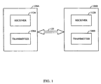
- FIG. 1 is a diagram illustrating an exemplary communication system 100 .
- the exemplary communication system has two transceivers 104 a and 104 b.
- Transceivers 104 a and 104 b each have a transmitter 108 a and 108 b, and a receiver 112 a and 112 b, respectively.
- Transmission path 122 is the air.
- transmission path 122 can be a wire or other signal transfer medium known in the art.
- transmission path 122 is a packetized data path in which the data are transmitted in data packets. This is usually the case where the information is in the form of digital data. In other environments, analog data are modulated onto a carrier and transmitted across transmission path 122 .
- one transceiver 104 can be, or is located in, a hand-held or mobile cellular telephone and the other transceiver 104 ( 104 b, 104 a) is located in a base station at a cell site that is providing service in the wireless device's or telephone's current physical location area.
- one transceiver 104 can be a hand-held, mobile, or fixed transceiver (e.g., a satellite telephone) and the other transceiver 104 ( 104 b, 104 a) is located in a gateway (or an earth station gateway).
- a satellite (not illustrated) is used to relay signals between transceivers 104 ( 104 a, 104 b), as is well known in the art.
- transceivers 104 104 a, 104 b
- one transceiver 104 can be located on board the satellite itself.
- tracking mode there are at least two modes of power control: “tracking mode” and “burst mode.” Both the tracking mode and burst mode of power control provide increases in power when system performance falls below an acceptable level. However, in burst mode, the amount of the power increase is greater than that provided in the tracking mode.
- Selection between the tracking mode and the burst mode is accomplished based on the system performance of the communication link. Specifically, if the system performance is within a preselected or defined nominal range, the tracking mode is utilized. If, however, system performance falls below this nominal range, the burst mode of power control is utilized. Utilization of the burst mode brings the system performance to the nominal range more quickly than would otherwise be the case for the tracking mode.
- the tracking mode is well suited to controlling power in nominal operating conditions where the SNR is varying by small amounts above and below the threshold level.
- burst mode is well suited for controlling power in conditions where large power drop-offs are experienced. Such conditions can result where, for example, the communication path is blocked by a large building or other interfering structure or condition.
- system performance is based on the signal-to-noise ratio (SNR) of a signal transmitted by a transmitter (such as transmitter 108 a or 108 b).
- the tracking mode increases the power in small increments when the signal-to-noise ratio (SNR) falls below an acceptable level.
- Burst mode also increases the power when the signal-to-noise ratio (SNR) falls below an acceptable level.
- SNR signal-to-noise ratio
- burst mode the amount of the power increase is greater than that provided in the tracking mode. Selection between the two modes is accomplished based on how far the SNR falls below the acceptable level. That is, based on whether or not the performance of the communication link is considered nominal.
- system performance is based on receive signal strength independent of the SNR.
- system performance is based on the number of frames received with errors.
- the burst mode is selected for controlling power. If, on the other hand, the receiver receives only occasional frame errors, tracking mode is selected.
- the power increase for each mode is incremental. That is, for a given command or decision to increase the power, the power is increased by a preselected incremental amount. Power is not increased again until a subsequent command or decision is made to again increase the power. In an alternative embodiment, for a given command or decision to increase the power, the power increases gradually until a subsequent command is received to terminate the power increase. In either embodiment, burst mode provides a greater increase in power than the tracking mode. That is, the burst mode provides a larger incremental power increase in the first embodiment and a more rapid rate of increase in the second embodiment.
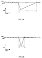
- FIG. 2 A is a diagram illustrating an exemplary operational scenario where power is controlled in only the tracking mode.
- the horizontal axis represents time and the vertical axis represents SNR.
- the threshold SNR is illustrated by horizontal line 204 .
- An example of the actual SNR of the transmitted signal is illustrated by the time-varying line 208 .
- the device is operating nominally up until a time T 1 .
- SNR 208 of transmitter 108 is varying by a small amount about SNR threshold 204 . Adjustments are made to the transmitted power in small increments.
- SNR 208 falls below threshold 204 , power is incrementally increased.
- SNR 208 rises above threshold 204 power is incrementally decreased. Power adjustments for transmitters are made using commands or control and operation techniques well known in the art.
- the SNR for signals traversing transmission path 122 drops significantly. This can occur where, for example, the path is obstructed.
- the power is increased incrementally to improve the SNR.
- a significant amount of time elapses before the SNR again reaches an acceptable level. This is illustrated by the time duration tt.
- FIG. 2 B is a diagram illustrating an exemplary operational scenario where power is selectively controlled in both the tracking mode and the burst mode.
- the horizontal axis represents time and the vertical axis represents SNR.
- the threshold SNR is illustrated by horizontal line 204 .
- An example of the actual SNR of the transmitted signal is illustrated by the time-varying line 208 .
- the device is operating nominally up until time T 1 .
- SNR 208 of a transmitter 108 transmitted signal is varying by a small amount about SNR threshold 204 .
- transmitter 108 is operating in the tracking mode and adjustments are made to the transmitted power in small increments.
- power is incrementally increased.
- the transmitter power control mode is switched to the burst mode.
- the power increase is more significant than in the tracking mode.
- the amount of time, t b that it takes for the SNR to return to an acceptable level is much shorter than the time t t required in the tracking mode.
- transmitter 108 is switched to tracking mode.
- selection of the power control mode is made by a receiver 112 .
- receiver 112 ( 112 a, 112 b) instructs transmitter 108 ( 108 b, 108 a) (of opposite transceiver 104 ) to switch power control modes when necessary. This can be done, for example, in a command portion of the transmitted signal.
- receiver 112 provides information back to transmitter 104 to enable transmitter 104 to make a decision as to whether or not to switch power control modes.
- receiver 112 may send one or more indications such as a frame error indication, such as a bit error rate value, a SNR value, or some other indication of whether or not the transmission is within nominal or desired characteristics to transmitter 108 (receiver 104 ).
- a frame error indication such as a bit error rate value, a SNR value, or some other indication of whether or not the transmission is within nominal or desired characteristics
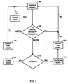
- FIG. 3 is an operational flow diagram generally illustrating a process of determining and selecting an appropriate power control mode according to one embodiment of the invention.
- receiver 112 receives a signal transmitted by transmitter 108 ( 108 b, 108 a).
- the signal is transmitted across transmission path 122 .
- Receiver 112 determines whether or not SNR 208 of the received signal is above, at or below a preselected threshold 204 . This can be done regardless of the power control mode in which the communication system is operating. This decision is illustrated by a decision step 308 . If SNR 208 of the received signal is above threshold 204 , the power is adjusted down and the operation returns to step 304 where receiver 108 continues to receive the transmitted signal. This is illustrated by step 310 and flow line 362 .
- threshold 204 is not implemented as a single value, but instead encompasses an acceptable range of SNR values.
- step 312 receiver 112 determines whether or not the degradation in SNR 208 is greater than the desired nominal value. In other words, receiver 112 determines if SNR 208 is more than an acceptable amount below threshold 204 and, therefore, if the tracking mode is undesirable because it would take longer than desired to return the SNR 208 to threshold 204 .
- step or block 316 power is controlled using or by selecting the tracking mode as illustrated by step or block 316 . If the power control mode is already the tracking mode, transmitter 108 remains in the tracking mode. However, if the current power control mode is burst mode, step 316 represents changing from burst mode to tracking mode. In a step 320 , the power of the transmitter is adjusted in or during the tracking mode operation. Receiver 112 continues to receive the transmission as illustrated by flow lines 366 , 364 .
- the power control mode is selected as the burst mode as illustrated by step or block 326 . If the power control mode is already the burst mode, transmitter 108 remains in the burst mode. However, if the current power control mode is the tracking mode, step 326 represents a change from the tracking mode to the burst mode. In a step 330 , the power is adjusted in or during the burst mode operation. Receiver 112 continues to receive the transmission as illustrated by flow line 368 .
- threshold 204 is not a single value, but a range of values, such that as long as the received signal SNR falls within that range, the signal is said to be at threshold.
- the determination made in steps 308 and 312 is not made based on the SNR per se, but is instead made based on the number of frames received with one or more errors.
- receiver 112 determines how many frames of the past X number of frames were received with errors. In this example, if more than Y out of the last X frames were received with errors, this represents an error rate beyond nominal range and the preferred power control mode is the burst mode.
- receiver 112 determines how many consecutive frames were received with errors. If the number of consecutive frames received with errors meets or exceeds a predetermined limit, this represents an error rate beyond nominal range and the preferred power control mode is the burst mode. Determining the number of frames received with errors can be accomplished using known techniques such as, for example, by way of a cyclic redundancy check (CRC) code.
- CRC cyclic redundancy check
- the invention looks at the bit error rate (BER) of the received signal.
- BER bit error rate
- the BER rising above a threshold is analogous to the SNR 208 falling below threshold 204 . If the BER rises above threshold by more than a predetermined amount, the system is no longer operating nominally and the preferred power control mode is burst mode.
- receiver 112 is described as determining whether or not the system is at, above, or below threshold and whether the system is operating nominally.
- receiver 112 ( 112 a, 112 b) sends a command to transmitter 108 ( 108 b, 108 a) instructing transmitter 108 to change modes when appropriate.
- receiver 112 simply provides telemetry to transmitter 108 . This telemetry provides transmitter 108 with sufficient information to determine whether the preferred mode is the tracking mode or burst mode.
- the receiver provides two feedback indicators in the form of bits in a message or command.
- One bit is used to indicate the "tracking mode up/down command" and the other indicates “burst mode transmit level adjustment.” It is up to the transmitter to decide what is acted upon or implemented. A decision is made by the transmitter based on factors, such as, but not limited to, the number of consecutive frame errors, etc. In this approach, a faster reaction time is provided for the system because significant events such as errors are immediately reported to the transmitter, at the cost of increased bandwidth consumed for power control purposes.
- receiver 112 commands transmitter 108 to switch power control modes
- This scenario can be handled using any of several different techniques.
- One technique uses acknowledgment messages to confirm receipt of the command.
- a second technique is to simply continue sending the command. For example, if the system is operating out of nominal bounds, receiver 112 sends a command to track in the burst mode during each command frame until the system has returned to nominal operation. Because the command is repeated, and because this repetition is, in many cases, unnecessary, this technique consumes more bandwidth than is required. For this reason, this technique may be undesirable.
- the implementation, or not, of a power control mode change is ignored. That is, there is no checking to determine whether transmitter 108 has indeed switched power control modes as commanded.
- this embodiment may seem counter-intuitive, it is actually a preferred embodiment.
- SNR 208 has decreased substantially and receiver 112 commands transmitter 108 to switch power control modes to the burst mode. If transmitter 108 does not receive this command, the only negative result is that transmitter 108 continues to control the power in the tracking mode. That is, it takes longer to return to nominal operation than would otherwise be the case if the command were received by transmitter 108 .
- transmitter 108 In a second situation, transmitter 108 is operating in the burst mode and the signal is returned to the nominal range. If transmitter 108 does not receive the command from receiver 112 instructing a change to the tracking mode, power may be increased greater than otherwise required. However, this is not a fatal error as the system continues to operate. The only disadvantage is that more power is being consumed than would otherwise be required.
Landscapes
- Engineering & Computer Science (AREA)
- Computer Networks & Wireless Communication (AREA)
- Signal Processing (AREA)
- Quality & Reliability (AREA)
- Mobile Radio Communication Systems (AREA)
- Transmitters (AREA)
- Cable Transmission Systems, Equalization Of Radio And Reduction Of Echo (AREA)
- Coloring Foods And Improving Nutritive Qualities (AREA)
- Crystals, And After-Treatments Of Crystals (AREA)
- Diaphragms For Electromechanical Transducers (AREA)
Applications Claiming Priority (7)
| Application Number | Priority Date | Filing Date | Title |
|---|---|---|---|
| US62821 | 1979-08-01 | ||
| US6282197P | 1997-10-13 | 1997-10-13 | |
| US6281997P | 1997-10-13 | 1997-10-13 | |
| US62819 | 1997-10-13 | ||
| US09/164,383 US6185432B1 (en) | 1997-10-13 | 1998-09-30 | System and method for selecting power control modes |
| US164383 | 1998-09-30 | ||
| PCT/US1998/021252 WO1999020005A2 (en) | 1997-10-13 | 1998-10-05 | Apparatus and method for selecting power control modes |
Publications (2)
| Publication Number | Publication Date |
|---|---|
| EP1048115A1 EP1048115A1 (en) | 2000-11-02 |
| EP1048115B1 true EP1048115B1 (en) | 2005-12-07 |
Family
ID=27370376
Family Applications (1)
| Application Number | Title | Priority Date | Filing Date |
|---|---|---|---|
| EP98953323A Expired - Lifetime EP1048115B1 (en) | 1997-10-13 | 1998-10-05 | Apparatus and method for selecting power control modes |
Country Status (10)
Families Citing this family (59)
| Publication number | Priority date | Publication date | Assignee | Title |
|---|---|---|---|---|
| JPH11196456A (ja) * | 1998-01-05 | 1999-07-21 | Oki Electric Ind Co Ltd | 送信電力制御装置 |
| EP1758266A3 (en) * | 1998-03-03 | 2014-04-23 | NEC Corporation | Method of controlling transmission power in a cellular type mobile communication system |
| US6463296B1 (en) * | 1999-02-16 | 2002-10-08 | Telefonaktiebolaget L M Ericsson (Publ) | Power control in a CDMA mobile communications system |
| EP1037396B1 (en) * | 1999-03-16 | 2012-05-02 | Alcatel Lucent | A method for improving performances of a mobile radiocommunication system using a power control algorithm |
| US6334047B1 (en) * | 1999-04-09 | 2001-12-25 | Telefonaktiebolaget Lm Ericsson (Publ) | Adaptive power control in a mobile radio communications system |
| EP1061668B1 (en) * | 1999-06-16 | 2004-08-18 | Alcatel | A method for improving performances of a mobile radiocommunication system using a power control algorithm |
| US6490461B1 (en) * | 1999-06-24 | 2002-12-03 | Telefonaktiebolaget Lm Ericsson (Publ) | Power control based on combined quality estimates |
| CN101034919A (zh) * | 2000-02-23 | 2007-09-12 | Ipr特许公司 | 反向链路初始功率的设定 |
| US6430418B1 (en) * | 2000-06-19 | 2002-08-06 | Trw Inc. | Method and system for controlling uplink power in a satellite communication system using error leveling |
| US6876866B1 (en) * | 2000-07-13 | 2005-04-05 | Qualcomm Incorporated | Multi-state power control mechanism for a wireless communication system |
| JP3573073B2 (ja) | 2000-08-09 | 2004-10-06 | 日本電気株式会社 | 送信電力制御システム及びそれに用いる送信電力制御方法 |
| JP3479839B2 (ja) | 2000-10-27 | 2003-12-15 | 日本電気株式会社 | 受信agc回路 |
| US7082107B1 (en) | 2001-11-26 | 2006-07-25 | Intel Corporation | Power control in wireless communications based on estimations of packet error rate |
| US7254195B2 (en) * | 2003-08-25 | 2007-08-07 | M/A-Com, Inc. | Apparatus, methods and articles of manufacture for dynamic differential delay correction |
| US7221915B2 (en) * | 2003-06-25 | 2007-05-22 | M/A-Com, Inc. | Electromagnetic wave transmitter, receiver and transceiver systems, methods and articles of manufacture |
| US7151913B2 (en) * | 2003-06-30 | 2006-12-19 | M/A-Com, Inc. | Electromagnetic wave transmitter, receiver and transceiver systems, methods and articles of manufacture |
| US7751496B2 (en) * | 2003-06-25 | 2010-07-06 | Pine Valley Investments, Inc. | Electromagnetic wave transmitter, receiver and transceiver systems, methods and articles of manufacture |
| US6882857B2 (en) * | 2002-11-26 | 2005-04-19 | Qualcomm, Incorporated | Method and apparatus for efficient processing of data for transmission in a communication system |
| MXPA05005932A (es) | 2002-12-04 | 2005-08-18 | Interdigital Tech Corp | Deteccion de confiabilidad del indicador de calidad de canal (cqi) y aplicacion a control de potencia de bucle externo. |
| GB2396523B (en) * | 2002-12-17 | 2006-01-25 | Motorola Inc | Method and apparatus for power control for a transmitter in a cellular communication system |
| US7738848B2 (en) | 2003-01-14 | 2010-06-15 | Interdigital Technology Corporation | Received signal to noise indicator |
| US6859098B2 (en) | 2003-01-17 | 2005-02-22 | M/A-Com, Inc. | Apparatus, methods and articles of manufacture for control in an electromagnetic processor |
| US7149538B2 (en) * | 2003-02-13 | 2006-12-12 | Telefonaktiebolaget Lm Ericsson (Publ) | Wireless transceivers, methods, and computer program products for restricting transmission power based on signal-to-interference ratios |
| US7091778B2 (en) * | 2003-09-19 | 2006-08-15 | M/A-Com, Inc. | Adaptive wideband digital amplifier for linearly modulated signal amplification and transmission |
| US7480511B2 (en) * | 2003-09-19 | 2009-01-20 | Trimble Navigation Limited | Method and system for delivering virtual reference station data |
| CN1691524B (zh) * | 2004-04-28 | 2011-06-29 | 智易科技股份有限公司 | 无线通讯装置的射频输出功率控制方法 |
| US20060218271A1 (en) * | 2005-03-16 | 2006-09-28 | Nokia Corporation | Triggered statistics reporting |
| US7345534B2 (en) * | 2005-05-31 | 2008-03-18 | M/A-Com Eurotec Bv | Efficient power amplification system |
| US7392021B2 (en) * | 2005-08-03 | 2008-06-24 | M/A-Com, Inc. | Apparatus, system, and method for measuring power delivered to a load |
| US20070087770A1 (en) * | 2005-10-14 | 2007-04-19 | Hong Gan | Methods and apparatuses for transmission power control in a wireless communication system |
| JP4684888B2 (ja) * | 2005-12-28 | 2011-05-18 | キヤノン株式会社 | 通信装置及び電力制御方法 |
| US8315226B2 (en) * | 2006-01-05 | 2012-11-20 | Qualcomm Incorporated | Power control and handoff with power control commands and erasure indications |
| KR101205847B1 (ko) * | 2006-01-17 | 2012-12-03 | 삼성전자주식회사 | 무선 통신 시스템에서 컨트롤 채널의 디코딩 방법과 그장치 |
| JP5036212B2 (ja) * | 2006-04-21 | 2012-09-26 | キヤノン株式会社 | 通信装置及びその送信電力制御方法 |
| US7643800B2 (en) * | 2007-01-30 | 2010-01-05 | Broadcom Corporation | Transmit power management for a communication device and method for use therewith |
| GB2447889B (en) * | 2007-03-21 | 2012-02-29 | Motorola Mobility Inc | Power control in a cellular communication system |
| US20090027112A1 (en) * | 2007-07-26 | 2009-01-29 | Chin Li | Controllable precision transconductance |
| US7671699B2 (en) * | 2007-08-14 | 2010-03-02 | Pine Valley Investments, Inc. | Coupler |
| US9363469B2 (en) * | 2008-07-17 | 2016-06-07 | Ppc Broadband, Inc. | Passive-active terminal adapter and method having automatic return loss control |
| US8356322B2 (en) | 2009-09-21 | 2013-01-15 | John Mezzalingua Associates, Inc. | Passive multi-port entry adapter and method for preserving downstream CATV signal strength within in-home network |
| US9647851B2 (en) | 2008-10-13 | 2017-05-09 | Ppc Broadband, Inc. | Ingress noise inhibiting network interface device and method for cable television networks |
| US9351051B2 (en) | 2008-10-13 | 2016-05-24 | Ppc Broadband, Inc. | CATV entry adapter and method for distributing CATV and in-home entertainment signals |
| US8429695B2 (en) * | 2008-10-21 | 2013-04-23 | Ppc Broadband, Inc. | CATV entry adapter and method utilizing directional couplers for MoCA signal communication |
| US8286209B2 (en) * | 2008-10-21 | 2012-10-09 | John Mezzalingua Associates, Inc. | Multi-port entry adapter, hub and method for interfacing a CATV network and a MoCA network |
| US10154302B2 (en) | 2008-10-13 | 2018-12-11 | Ppc Broadband, Inc. | CATV entry adapter and method for distributing CATV and in-home entertainment signals |
| US8510782B2 (en) | 2008-10-21 | 2013-08-13 | Ppc Broadband, Inc. | CATV entry adapter and method for preventing interference with eMTA equipment from MoCA Signals |
| US11910052B2 (en) | 2008-10-21 | 2024-02-20 | Ppc Broadband, Inc. | Entry device for communicating external network signals and in-home network signals |
| US8350641B2 (en) * | 2010-01-26 | 2013-01-08 | John Mezzalingua Associates, Inc. | Band selective isolation bridge for splitter |
| US8487717B2 (en) | 2010-02-01 | 2013-07-16 | Ppc Broadband, Inc. | Multipath mitigation circuit for home network |
| KR101624907B1 (ko) * | 2010-03-16 | 2016-06-08 | 삼성전자주식회사 | 광대역 무선통신 시스템에서 실내 기지국의 송신 전력 제어 장치 및 방법 |
| US8479247B2 (en) | 2010-04-14 | 2013-07-02 | Ppc Broadband, Inc. | Upstream bandwidth conditioning device |
| US8561125B2 (en) | 2010-08-30 | 2013-10-15 | Ppc Broadband, Inc. | Home network frequency conditioning device and method |
| CA2831220C (en) | 2010-12-21 | 2022-05-31 | Ppc Broadband, Inc. | Method and apparatus for reducing isolation in a home network |
| US9264012B2 (en) | 2012-06-25 | 2016-02-16 | Ppc Broadband, Inc. | Radio frequency signal splitter |
| JP2015162707A (ja) * | 2014-02-26 | 2015-09-07 | 株式会社ダイヘン | 通信装置、溶接電源装置、ワイヤ送給装置、溶接システム、および、制御方法 |
| CA3028756A1 (en) | 2016-06-30 | 2018-01-04 | Ppc Broadband, Inc. | Passive enhanced moca entry device |
| CN108259071B (zh) | 2016-12-28 | 2019-02-26 | 上海朗帛通信技术有限公司 | 一种被用于多天线传输的ue、基站中的方法和装置 |
| CN108923896B (zh) | 2017-04-19 | 2021-03-26 | 上海朗帛通信技术有限公司 | 一种被用于寻呼的用户设备、基站中的方法和装置 |
| WO2019143613A2 (en) | 2018-01-19 | 2019-07-25 | Ppc Broadband, Inc. | Systems and methods for extending an in-home splitter network |
Family Cites Families (7)
| Publication number | Priority date | Publication date | Assignee | Title |
|---|---|---|---|---|
| IE62238B1 (en) | 1988-02-25 | 1995-01-11 | Dieter Stephan | Process and apparatus for producing blister packs |
| DE69231437T2 (de) | 1991-12-26 | 2001-03-01 | Nec Corp., Tokio/Tokyo | System zur Steuerung der Sendeleistung mit Gewährleistung einer konstanten Signalqualität in einem Mobilkommunikationsnetzwerk |
| US5333175A (en) | 1993-01-28 | 1994-07-26 | Bell Communications Research, Inc. | Method and apparatus for dynamic power control in TDMA portable radio systems |
| US5383219A (en) * | 1993-11-22 | 1995-01-17 | Qualcomm Incorporated | Fast forward link power control in a code division multiple access system |
| US5873028A (en) | 1994-10-24 | 1999-02-16 | Ntt Mobile Communications Network Inc. | Transmission power control apparatus and method in a mobile communication system |
| GB2301741A (en) | 1995-06-02 | 1996-12-11 | Dsc Communications | Establishing a Downlink Communication Path in a Wireless Communications System |
| EP1048131B1 (en) * | 1997-10-13 | 2005-07-27 | QUALCOMM Incorporated | Apparatus and method for optimized power control |
-
1998
- 1998-09-30 US US09/164,383 patent/US6185432B1/en not_active Expired - Lifetime
- 1998-10-05 KR KR1020007003952A patent/KR100750433B1/ko not_active Expired - Fee Related
- 1998-10-05 AU AU10728/99A patent/AU742648B2/en not_active Ceased
- 1998-10-05 DE DE69832727T patent/DE69832727T2/de not_active Expired - Lifetime
- 1998-10-05 JP JP2000516450A patent/JP2001520478A/ja active Pending
- 1998-10-05 WO PCT/US1998/021252 patent/WO1999020005A2/en active IP Right Grant
- 1998-10-05 EP EP98953323A patent/EP1048115B1/en not_active Expired - Lifetime
- 1998-10-05 CN CNB988101181A patent/CN1211946C/zh not_active Expired - Fee Related
- 1998-10-05 AT AT98953323T patent/ATE312436T1/de not_active IP Right Cessation
- 1998-10-05 CA CA002306921A patent/CA2306921C/en not_active Expired - Fee Related
Also Published As
| Publication number | Publication date |
|---|---|
| CN1276111A (zh) | 2000-12-06 |
| WO1999020005A2 (en) | 1999-04-22 |
| DE69832727D1 (de) | 2006-01-12 |
| EP1048115A1 (en) | 2000-11-02 |
| WO1999020005A3 (en) | 1999-06-24 |
| CA2306921A1 (en) | 1999-04-22 |
| KR100750433B1 (ko) | 2007-08-21 |
| US6185432B1 (en) | 2001-02-06 |
| AU742648B2 (en) | 2002-01-10 |
| ATE312436T1 (de) | 2005-12-15 |
| CN1211946C (zh) | 2005-07-20 |
| CA2306921C (en) | 2005-04-26 |
| AU1072899A (en) | 1999-05-03 |
| DE69832727T2 (de) | 2006-08-17 |
| KR20010031086A (ko) | 2001-04-16 |
| JP2001520478A (ja) | 2001-10-30 |
Similar Documents
| Publication | Publication Date | Title |
|---|---|---|
| EP1048115B1 (en) | Apparatus and method for selecting power control modes | |
| US6259928B1 (en) | System and method for optimized power control | |
| AU757622B2 (en) | Apparatus and method for optimized power control | |
| US5787338A (en) | Method and apparatus for controlling operation of a portable or mobile battery-operated radios | |
| EP0986868B1 (en) | Enhanced reverse link power control in a wireless communication system | |
| US6137789A (en) | Mobile station employing selective discontinuous transmission for high speed data services in CDMA multi-channel reverse link configuration | |
| EP1162766B1 (en) | Method and device for transmitting burst signal in mobile communication system, information distribution method, and information distribution controller | |
| EP1142159A1 (en) | Data transmission method and radio system | |
| KR100634575B1 (ko) | 업링크 성능 향상을 위한 적응변조코딩 방법 및 장치 | |
| US7308281B2 (en) | Optimal two-leg histeresys for power control and phy mode switching control in adaptive phy mode systems | |
| KR100396669B1 (ko) | 역방향 링크의 데이터 전송율 제어 방법 및 이를 위한단말기 | |
| US20040248584A1 (en) | Mobile body communication system, radio communication control apparatus mobile body communication apparatus, and mobile body communication method | |
| HK1033050B (en) | Apparatus and method for optimized power control | |
| HK1033512A1 (en) | Apparatus and method for selecting power control modes | |
| HK1033512B (en) | Apparatus and method for selecting power control modes | |
| WO1999023772A1 (en) | Method and apparatus for reducing the effect of a fading condition in a communication system | |
| HK1032494A (en) | Apparatus and method for optimized power control | |
| SE511167C2 (sv) | Förfarande för effektstyrning vid mjuk överlämning i telekommunikationssystem |
Legal Events
| Date | Code | Title | Description |
|---|---|---|---|
| PUAI | Public reference made under article 153(3) epc to a published international application that has entered the european phase |
Free format text: ORIGINAL CODE: 0009012 |
|
| 17P | Request for examination filed |
Effective date: 20000414 |
|
| AK | Designated contracting states |
Kind code of ref document: A1 Designated state(s): AT BE CH CY DE DK ES FI FR GB GR IE IT LI LU MC NL PT SE |
|
| AX | Request for extension of the european patent |
Free format text: AL PAYMENT 20000414;LT PAYMENT 20000414;LV PAYMENT 20000414;MK PAYMENT 20000414;RO PAYMENT 20000414;SI PAYMENT 20000414 |
|
| RAP1 | Party data changed (applicant data changed or rights of an application transferred) |
Owner name: QUALCOMM INCORPORATED |
|
| 17Q | First examination report despatched |
Effective date: 20030526 |
|
| GRAP | Despatch of communication of intention to grant a patent |
Free format text: ORIGINAL CODE: EPIDOSNIGR1 |
|
| GRAS | Grant fee paid |
Free format text: ORIGINAL CODE: EPIDOSNIGR3 |
|
| GRAA | (expected) grant |
Free format text: ORIGINAL CODE: 0009210 |
|
| AK | Designated contracting states |
Kind code of ref document: B1 Designated state(s): AT BE CH CY DE DK ES FI FR GB GR IE IT LI LU MC NL PT SE |
|
| AX | Request for extension of the european patent |
Extension state: AL LT LV MK RO SI |
|
| PG25 | Lapsed in a contracting state [announced via postgrant information from national office to epo] |
Ref country code: NL Free format text: LAPSE BECAUSE OF FAILURE TO SUBMIT A TRANSLATION OF THE DESCRIPTION OR TO PAY THE FEE WITHIN THE PRESCRIBED TIME-LIMIT Effective date: 20051207 Ref country code: LI Free format text: LAPSE BECAUSE OF FAILURE TO SUBMIT A TRANSLATION OF THE DESCRIPTION OR TO PAY THE FEE WITHIN THE PRESCRIBED TIME-LIMIT Effective date: 20051207 Ref country code: IT Free format text: LAPSE BECAUSE OF FAILURE TO SUBMIT A TRANSLATION OF THE DESCRIPTION OR TO PAY THE FEE WITHIN THE PRESCRIBED TIME-LIMIT;WARNING: LAPSES OF ITALIAN PATENTS WITH EFFECTIVE DATE BEFORE 2007 MAY HAVE OCCURRED AT ANY TIME BEFORE 2007. THE CORRECT EFFECTIVE DATE MAY BE DIFFERENT FROM THE ONE RECORDED. Effective date: 20051207 Ref country code: CH Free format text: LAPSE BECAUSE OF FAILURE TO SUBMIT A TRANSLATION OF THE DESCRIPTION OR TO PAY THE FEE WITHIN THE PRESCRIBED TIME-LIMIT Effective date: 20051207 Ref country code: BE Free format text: LAPSE BECAUSE OF FAILURE TO SUBMIT A TRANSLATION OF THE DESCRIPTION OR TO PAY THE FEE WITHIN THE PRESCRIBED TIME-LIMIT Effective date: 20051207 Ref country code: AT Free format text: LAPSE BECAUSE OF FAILURE TO SUBMIT A TRANSLATION OF THE DESCRIPTION OR TO PAY THE FEE WITHIN THE PRESCRIBED TIME-LIMIT Effective date: 20051207 |
|
| REG | Reference to a national code |
Ref country code: GB Ref legal event code: FG4D |
|
| REG | Reference to a national code |
Ref country code: CH Ref legal event code: EP |
|
| REG | Reference to a national code |
Ref country code: IE Ref legal event code: FG4D |
|
| REF | Corresponds to: |
Ref document number: 69832727 Country of ref document: DE Date of ref document: 20060112 Kind code of ref document: P |
|
| REG | Reference to a national code |
Ref country code: SE Ref legal event code: TRGR |
|
| PG25 | Lapsed in a contracting state [announced via postgrant information from national office to epo] |
Ref country code: GR Free format text: LAPSE BECAUSE OF FAILURE TO SUBMIT A TRANSLATION OF THE DESCRIPTION OR TO PAY THE FEE WITHIN THE PRESCRIBED TIME-LIMIT Effective date: 20060307 Ref country code: DK Free format text: LAPSE BECAUSE OF FAILURE TO SUBMIT A TRANSLATION OF THE DESCRIPTION OR TO PAY THE FEE WITHIN THE PRESCRIBED TIME-LIMIT Effective date: 20060307 |
|
| PG25 | Lapsed in a contracting state [announced via postgrant information from national office to epo] |
Ref country code: ES Free format text: LAPSE BECAUSE OF FAILURE TO SUBMIT A TRANSLATION OF THE DESCRIPTION OR TO PAY THE FEE WITHIN THE PRESCRIBED TIME-LIMIT Effective date: 20060318 |
|
| PG25 | Lapsed in a contracting state [announced via postgrant information from national office to epo] |
Ref country code: PT Free format text: LAPSE BECAUSE OF FAILURE TO SUBMIT A TRANSLATION OF THE DESCRIPTION OR TO PAY THE FEE WITHIN THE PRESCRIBED TIME-LIMIT Effective date: 20060508 |
|
| LTIE | Lt: invalidation of european patent or patent extension |
Effective date: 20051207 |
|
| NLV1 | Nl: lapsed or annulled due to failure to fulfill the requirements of art. 29p and 29m of the patents act | ||
| REG | Reference to a national code |
Ref country code: CH Ref legal event code: PL |
|
| ET | Fr: translation filed | ||
| PG25 | Lapsed in a contracting state [announced via postgrant information from national office to epo] |
Ref country code: IE Free format text: LAPSE BECAUSE OF NON-PAYMENT OF DUE FEES Effective date: 20061005 |
|
| PLBE | No opposition filed within time limit |
Free format text: ORIGINAL CODE: 0009261 |
|
| STAA | Information on the status of an ep patent application or granted ep patent |
Free format text: STATUS: NO OPPOSITION FILED WITHIN TIME LIMIT |
|
| PG25 | Lapsed in a contracting state [announced via postgrant information from national office to epo] |
Ref country code: MC Free format text: LAPSE BECAUSE OF NON-PAYMENT OF DUE FEES Effective date: 20061031 |
|
| 26N | No opposition filed |
Effective date: 20060908 |
|
| REG | Reference to a national code |
Ref country code: IE Ref legal event code: MM4A |
|
| PG25 | Lapsed in a contracting state [announced via postgrant information from national office to epo] |
Ref country code: LU Free format text: LAPSE BECAUSE OF NON-PAYMENT OF DUE FEES Effective date: 20061005 |
|
| PG25 | Lapsed in a contracting state [announced via postgrant information from national office to epo] |
Ref country code: CY Free format text: LAPSE BECAUSE OF FAILURE TO SUBMIT A TRANSLATION OF THE DESCRIPTION OR TO PAY THE FEE WITHIN THE PRESCRIBED TIME-LIMIT Effective date: 20051207 |
|
| PGFP | Annual fee paid to national office [announced via postgrant information from national office to epo] |
Ref country code: SE Payment date: 20100923 Year of fee payment: 13 Ref country code: FR Payment date: 20101004 Year of fee payment: 13 |
|
| PGFP | Annual fee paid to national office [announced via postgrant information from national office to epo] |
Ref country code: GB Payment date: 20100923 Year of fee payment: 13 |
|
| PGFP | Annual fee paid to national office [announced via postgrant information from national office to epo] |
Ref country code: FI Payment date: 20101008 Year of fee payment: 13 Ref country code: DE Payment date: 20101029 Year of fee payment: 13 |
|
| PGFP | Annual fee paid to national office [announced via postgrant information from national office to epo] |
Ref country code: IT Payment date: 20101021 Year of fee payment: 13 |
|
| GBPC | Gb: european patent ceased through non-payment of renewal fee |
Effective date: 20111005 |
|
| REG | Reference to a national code |
Ref country code: SE Ref legal event code: EUG |
|
| REG | Reference to a national code |
Ref country code: FR Ref legal event code: ST Effective date: 20120629 |
|
| PG25 | Lapsed in a contracting state [announced via postgrant information from national office to epo] |
Ref country code: DE Free format text: LAPSE BECAUSE OF NON-PAYMENT OF DUE FEES Effective date: 20120501 |
|
| REG | Reference to a national code |
Ref country code: DE Ref legal event code: R119 Ref document number: 69832727 Country of ref document: DE Effective date: 20120501 |
|
| PG25 | Lapsed in a contracting state [announced via postgrant information from national office to epo] |
Ref country code: FR Free format text: LAPSE BECAUSE OF NON-PAYMENT OF DUE FEES Effective date: 20111102 Ref country code: FI Free format text: LAPSE BECAUSE OF NON-PAYMENT OF DUE FEES Effective date: 20111005 Ref country code: GB Free format text: LAPSE BECAUSE OF NON-PAYMENT OF DUE FEES Effective date: 20111005 Ref country code: IT Free format text: LAPSE BECAUSE OF NON-PAYMENT OF DUE FEES Effective date: 20111005 |
|
| PG25 | Lapsed in a contracting state [announced via postgrant information from national office to epo] |
Ref country code: SE Free format text: LAPSE BECAUSE OF NON-PAYMENT OF DUE FEES Effective date: 20111006 |