EP1047013B1 - System and method for interfacing data stored on a magnetic strip - Google Patents
System and method for interfacing data stored on a magnetic strip Download PDFInfo
- Publication number
- EP1047013B1 EP1047013B1 EP00301178A EP00301178A EP1047013B1 EP 1047013 B1 EP1047013 B1 EP 1047013B1 EP 00301178 A EP00301178 A EP 00301178A EP 00301178 A EP00301178 A EP 00301178A EP 1047013 B1 EP1047013 B1 EP 1047013B1
- Authority
- EP
- European Patent Office
- Prior art keywords
- data
- track
- transmit
- control mechanism
- handler
- Prior art date
- Legal status (The legal status is an assumption and is not a legal conclusion. Google has not performed a legal analysis and makes no representation as to the accuracy of the status listed.)
- Expired - Lifetime
Links
Images


Classifications
-
- G—PHYSICS
- G06—COMPUTING OR CALCULATING; COUNTING
- G06K—GRAPHICAL DATA READING; PRESENTATION OF DATA; RECORD CARRIERS; HANDLING RECORD CARRIERS
- G06K7/00—Methods or arrangements for sensing record carriers, e.g. for reading patterns
- G06K7/08—Methods or arrangements for sensing record carriers, e.g. for reading patterns by means detecting the change of an electrostatic or magnetic field, e.g. by detecting change of capacitance between electrodes
- G06K7/082—Methods or arrangements for sensing record carriers, e.g. for reading patterns by means detecting the change of an electrostatic or magnetic field, e.g. by detecting change of capacitance between electrodes using inductive or magnetic sensors
- G06K7/083—Methods or arrangements for sensing record carriers, e.g. for reading patterns by means detecting the change of an electrostatic or magnetic field, e.g. by detecting change of capacitance between electrodes using inductive or magnetic sensors inductive
- G06K7/084—Methods or arrangements for sensing record carriers, e.g. for reading patterns by means detecting the change of an electrostatic or magnetic field, e.g. by detecting change of capacitance between electrodes using inductive or magnetic sensors inductive sensing magnetic material by relative movement detecting flux changes without altering its magnetised state
Definitions
- the present invention generally relates to data processing techniques and, in particular, to a system and method for reading data from a magnetic strip and for interfacing the data with electrical systems.
- a magnetic strip located on a plastic card or other device.
- a magnetic strip also known as a magnetic stripe
- the credit card is swiped through a card reader that reads information from the magnetic strip and processes the data from the magnetic strip through techniques well known in the art.
- the card reader often includes three separate reading devices that read information from a respective track of the magnetic strip.
- Each reading device serially transmits the data read from the magnetic strip to a computer system that processes the data.
- each reading device transmits a notification signal to the computer system prior to reading data from the magnetic strip.
- the computer system prepares to receive data. After the notification signal is transmitted, the reading device serially transmits the data read from the magnetic strip to the computer system.
- Serial transmission is inefficient because it takes a relatively long time to transmit the data bit by bit to the computer system.
- the computer system is usually required to respond to the notification messages from the reading devices even if there are other tasks that need to be performed by the computer system. If the computer system does not respond to a notification message in a timely fashion, then data could be lost.
- many computer systems are designed to immediately respond to notification messages from the reading devices even though it may be more efficient for the computer system to perform other tasks before receiving data from the reading devices.
- the computer system is usually required to receive data from each reading device separately. Therefore, the computer system is usually required to manage the reception of three separate and sometimes simultaneous flows of data from the reading devices.
- German patent DE 2 714 833 (the closest prior art) describes an arrangement for reading more than are magnetic strip simultaneously
- US patent 4,023,203 describes a method of simultaneous reading by delaying the signals of the respective strips.
- An embodiment of the present invention provides a system for interfacing data from magnetic strips, comprising: a magnetic strip interface configured to read data from a first track and a second track of a magnetic strip and to transmit the data; a first data handler coupled to said magnetic strip interface, said first data handler configured to receive the data read from the first track and to define a first data word based on the data read from the first track, said first data handler further configured to transmit the first data word in response to a first command signal; a second data handler coupled to said magnetic strip interface, said second data handler configured to receive the data read from the second track and to define a second data word based on the data read from the second track, said second data handler further configured to transmit the second data word in response to a second command signal; and a control mechanism configured to transmit the first command signal and the second command signal; characterised by said control mechanism being further configured to control when the first command signal and the second command signal are respectively transmitted to said first data handler and said second data handler based on a priority scheme.
- Another embodiment of the present invention provides a method for interfacing data from magnetic strips, comprising the steps of: reading data from a first track of a magnetic strip; reading data from a second track of a magnetic strip; converting the data from the first track into a first data word; converting the data from the second track into a second data word; transmitting the first data word; transmitting the second data word; and selectively controlling which of said transmitting steps to perform first based on a priority scheme.
- Fig. 1 depicts a magnetic strip reading system 15 of the prior art.
- the reading system 15 includes reading devices 18, which are each capable of reading a track of a magnetic strip. Therefore, the system 15 depicted by Fig. 1 is capable of reading up to three tracks of a magnetic strip.
- Each reading device 18 separately interfaces data from a respective track of the magnetic strip with a computer system 27.
- each reading device 18 serially transmits a data signal 21 and a clock signal 23 to the computer system 27, which processes the data signal 21 and clock signal 23 through known techniques.
- the data signal 21 and the clock signal 23 are defined by data read from the magnetic strip.
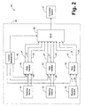
- Fig. 2 shows an embodiment of a magnetic strip reading system 35 in accordance with the present invention.
- the system 35 includes a computer system 37 and an integrated interface system 40 that interfaces data from a magnetic strip with the computer system 37.
- the interface system 40 includes data handlers 42 respectively connected to each reading device 18.
- Each data handler 42 is designed to receive the data signal 21 and clock signal 23, which are serial signals, and to transmit data word signals 47 to a multiplexer 52.
- Each data word signal 47 is defined by a plurality of bits from the data signals 21.
- a control mechanism 45 is configured to control the operation of the data handlers 42 and to prioritize the transmission of data to the computer system 37.
- the control mechanism 45 is implemented in hardware.
- the control mechanism 45 can also be implemented in software or a combination of hardware and software.
- the control mechanism 45 of the present invention along with its associated methodology is stored in computer memory 55 of a computer system 58.
- control mechanism 45 when implemented in software, can be stored and transported on any computer-readable medium for use by or in connection with an instruction execution system, apparatus, or device, such as a computer-based system, processor-containing system, or other system that can fetch the instructions from the instruction execution system, apparatus, or device and execute the instructions.
- a "computer-readable medium" can be any means that can contain, store, communicate, propagate, or transport the program for use by or in connection with the instruction execution system, apparatus, or device.
- the computer readable medium can be, for example but not limited to, an electronic, magnetic, optical, electromagnetic, infrared, or semiconductor system, apparatus, device, or propagation medium.
- the computer-readable medium would include the following: an electrical connection (electronic) having one or more wires, a portable computer diskette (magnetic), a random access memory (RAM) (magnetic), a read-only memory (ROM) (magnetic), an erasable programmable read-only memory (EPROM or Flash memory) (magnetic), an optical fiber (optical), and a portable compact disc read-only memory (CDROM) (optical).
- an electrical connection electronic having one or more wires
- a portable computer diskette magnetic
- RAM random access memory
- ROM read-only memory
- EPROM or Flash memory erasable programmable read-only memory
- CDROM portable compact disc read-only memory
- the computer-readable medium could even be paper or another suitable medium upon which the program is printed, as the program can be electronically captured, via for instance optical scanning of the paper or other medium, then compiled, interpreted or otherwise processed in a suitable manner if necessary, and then stored in a computer memory.
- the control mechanism 45 may be magnetically stored and transported on a conventional portable computer diskette.
- the computer system 58 of Fig. 3 comprises one or more conventional processing elements 62, such as a digital signal processor (DSP), that communicate to and drive the other elements within the system 58 via a local interface 65, which can include one or more buses.
- DSP digital signal processor
- an input device 67 for example, a keyboard or keypad, can be used to input data from a user of the system 58
- display 69 such as a liquid crystal display (LCD), or a printer 72 can be used to output data to the user.
- a disk storage mechanism 75 can be connected to the local interface 65 to transfer data to and from a nonvolatile disk (e.g. , magnetic, optical, etc. ).
- the system 58 can be connected to a network interface 77 that allows the system 58 to exchange data with a network 79.
- the reading devices 18, act as an interface data between a magnetic strip and the data handlers 42.
- the reading devices 18 are designed to read data from a magnetic strip, such as the magnetic strips located on the back of credit cards, automatic teller machine (ATM) cards , etc.
- Each reading device 18 is configured to transmit a serial data signal 21 and clock signal 23 to a respective data handler 42.
- the data signals 21 and the clock signals 23 represent data read from the magnetic strip.
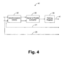
- Fig. 4 depicts a more detailed view of each data handler 42.
- Each of the data handlers 42 includes a snychronizing device 82, a serial-to-parallel converter 85, and a holding register 88.
- the synchronizing device 82 is designed to synchronize the data signal 21 and the clock signal 23 with the timing of the data handler 42. Once the data signal 21 and clock signal 23 are synchronized with the data handler 42, the synchronizing device 82 is configured to transmit the data signal 21 and the clock signal 23 to the serial-to-parallel converter 85.
- the serial-to-parallel converter 85 is configured to receive and store each bit of the data signal 21 transmitted from synchronizing device 82.
- the serial-to-parallel converter 85 is also designed to convert the serial data signal 21 from serial to parallel.
- the serial-to-parallel converter 85 uses the data received from signals 21, which have been synchronized with the data handler 42 by the synchronization device 82, to form a data word.
- a data word is a collection of data bits and can comprise any number of data bits.
- the serial-to-parallel converter 85 is designed to transmit the data word to holding register 88.
- the serial-to-parallel converter 85 transmits a notification signal to the control mechanism 45, when the serial-to-parallel converter 85 has received enough bits to define a data word. Therefore, the control mechanism 45 is aware when the serial-to-parallel converter 85 has defined a new data word. In response to the notification signal, the control mechanism 45 is designed to transmit a command signal to the serial-to-parallel converter 85 instructing the serial-to-parallel converter 85 to transmit the newly defined data word to holding register 88. In response to the command signal from control mechanism 45, the serial-to-parallel converter 85 is designed to transmit the newly defined data word to the holding register 88.
- serial-to-parallel converter 85 may be designed in other embodiments to transmit each newly defined data word to the holding register 88 without receiving commands from the control mechanism 45.
- a notification message it is still desirable for a notification message to be transmitted to the control mechanism 45 indicating when a new data word has been defined so that the control mechanism 45 is aware when data is ready for transmission to the computer system 37. It is possible for this notification message to be transmitted to the control mechanism 45 from other devices, such as the holding register 88, for example.
- the serial-to-parallel converter 85 preferably includes circuitry for detecting the occurrence of a data overrun.
- a data overrun can occur when data from reading device 18 overwrites data previously received by the serial-to-parallel converter 85 before the previously received data has been transmitted to the holding register 88.
- the serial-to-parallel converter 85 is configured to transmit a notification signal to the control mechanism 45 to indicate the occurrence of the overrun.
- the control mechanism is designed to transmit an interrupt signal, or other type of notification signal, to the computer system 37 to make the computer system 37 aware that the data being transmitted to the computer system 37 may be corrupted.
- the holding register 88 Upon receiving a newly defined data word from the serial-to-parallel converter 85, the holding register 88 is preferably configured to include a header on each data word to identify which track of the magnetic strip the data word is associated with. For example, assume that the magnetic strip includes three tracks of information such that each of the data handlers 42 corresponds to a respective track ( i.e. , each of the data handlers 42 processes data from a respective track of the magnetic strip). In the preferred embodiment, the holding register 88 corresponding with the first track (“track 1") inserts and asserts a header bit into each data word associated with track 1. Therefore, if a data word has an asserted header bit, then the data word is defined by data from track 1.
- the holding register 88 corresponding with the second track inserts and deasserts two header bits into each data word associated with track 2
- the holding register 88 corresponding with the third track inserts two header bits into each data word associated with track 3.
- the holding register 42 corresponding with the third track asserts the first header bit and deasserts the next header bit.
- the inserted header bits for each of the tracks are located at the most significant bit(s) location in each data word. Therefore, each data word having the most significant bit asserted is defined by data from track 1.
- each data word having the two most significant bits deasserted is defined by data from track 2, and each data word having the most significant bit deasserted and the next most significant bit asserted is defined by data from track 3.
- each data word may be comprised of different values, may include a different number of bits, and may be positioned in different locations within the data words.
- the holding register 88 is preferably designed as a first in, first out (FIFO) device. Therefore, the holding register 88 is configured to receive and store the parallel data words transmitted from the serial-to-parallel converter 85. In response to a transmit command from control mechanism 45, the holding register 88 is designed to transmit a data word to multiplexer 52 as signal 47. Since the holding register 88 is preferably a FIFO device, the data words are transmitted by the holding register 88 in the same order that the data words were received by the holding register 88. Therefore, the first data word received by the holding register 88 is the first data word transmitted by the holding register 88.
- FIFO first in, first out
- the control mechanism 45 is configured to prioritize the transmission of data from the data handlers 42.
- a predefined priority scheme 92 may be hardcoded in hardware or may be stored in memory 55.
- the term "predefined” or “predetermined” is relative to the data being processed by the system 35 and shall be defined to mean as determined or defined before the data being processed by the system 40 is read from the magnetic strip.
- the predefined priority scheme 92 indicates which data handler 42 should be given priority ( i.e. , be allowed to transmit data to the multiplexer 52 first) when more than one data handler 42 is simultaneously ready to transmit data to the multiplexer 52.
- the data handler 47 that is processing a larger amount of data is given a higher priority. Therefore, the data handler 47 with the largest of amount of data to transmit per stripe is selected as the data handler 42 with the highest priority.
- each track on each credit card includes approximately the same amount of information from card to card.
- Table 1 Table 1 Track Number Priority Bits/Inch (bpi) Number of Bits in the Header Bits/Data Word 1 2 210 1 7 2 3 75 2 6 3 1 210 2 6
- the data handler 42 associated with track 3 is required to transmit the most data for each swipe of the credit card and is assigned the highest priority ("priority 1") as a result.
- track 1 and track 3 include the same amount of data
- the data handler 42 associated with track 3 transmits more data because it has a two bit header instead of a one bit header, as described hereinbefore. Therefore, assuming that each data word transmitted from the holding register 88 is 8 bits in length, the data words associated with track 1 include 7 bits of data from the magnetic strip, whereas the data words associated with tracks 2 and 3 include only 6 bits of data from the magnetic strip. It should be noted that the number of bits defining the data words can vary without departing from the principles of the present invention.
- the data handler 42 associated with track 1 is required to transmit more data than the remaining data handler 42 (i.e. , the data handler 42 associated with track 2) and is, therefore, assigned the next highest priority ("priority 2").
- the data handler 42 associated with track 2 transmits the least amount of data for each swipe of the credit card and is, therefore, assigned the lowest priority ("priority 3").
- control mechanism 45 determines, based on the aforementioned notification signals transmitted to the control mechanism 45 by the serial-to-parallel converter 85, that one of the data handlers 42 is ready to transmit data to the multiplexer 52, the control mechanism 45 is designed to then determine whether there is more than one data handler 42 that is ready to transmit data. If there are no other data handlers 42 ready to transmit data, then the control mechanism 45 is designed to transmit a command signal to the holding register 88 of the data handler 42 that is ready to transmit data. In response, the holding register 88 transmits a data word to the multiplexer 52 as data signal 47.
- control mechanism 45 is designed to select the data handler 42 with the highest priority of the data handlers 42 that are ready to transmit data.
- the control mechanism 45 is then designed to transmit the command signal to the holding register 88 of the selected data handler 42.
- the holding register 88 of the selected data handler 42 transmits a data word to the multiplexer 52 as data signal 47.
- the control mechanism 45 After the control mechanism 45 transmits a control signal to the appropriate holding register 88, the control mechanism 45 is designed to determine if there are any data handlers 42 ready to transmit data. If there is a data handler 42 ready to transmit data at this point, the control mechanism 45 is designed to change the current priority scheme (i.e. , the priority scheme previously used to determine priority, which is the predefined priority scheme 92 in this example) to create a new priority scheme 95 ( Fig. 3 ). In this regard, the new priority scheme 95 corresponds to the current priority scheme, except that the data handler 42 that just transmitted data to the multiplexer 52 ( i.e. , the last data handler 42 to transmit data to the multiplexer 52) is assigned the lowest priority.
- the current priority scheme i.e. , the priority scheme previously used to determine priority, which is the predefined priority scheme 92 in this example
- the new priority scheme 95 corresponds to the current priority scheme, except that the data handler 42 that just transmitted data to the multiplexer 52 ( i.e
- the predefined priority scheme 92 and the new priority scheme 95 may be defined in hardware, software, or a combination thereof.
- the control mechanism 45 is configured to select the data handler 42 with the highest priority (based on the new priority scheme 95) of the data handlers 42 ready to transmit data. Then, the control mechanism 45 is designed to transmit a command signal to the holding register 88 of the selected data handler 42 to cause this holding register 88 to transmit data. If the control mechanism 45 determines that there are no data handlers 42 currently ready to transmit data, then the control mechanism 45 takes no further action until another notification message is received. Once this occurs, the control mechanism 45 is designed to use the predetermined priority scheme 92 again to determine priority between the data handlers 42 that are simultaneously ready to transmit data.
- the multiplexer 52 preferably receives control signals from the control mechanism 45, and based on these control signals, the multiplexer 52 is designed to multiplex the data word signals 47.
- the mulitplexer 52 based on the control signals received from control mechanism 45, selects one of the data word signals 47 to transmit to computer system 37 in the preferred embodiment. Therefore, the bus(es) connecting the multiplexer 52 with each of the data handlers 42 and the bus connecting the multiplexer 52 with the computer system 37 should correspond to the number of bits included in the data word signals 47 transmitted from the data handlers 42. For example, if the data handlers 42 are designed to transmit 8 bit data words, then the foregoing buses should correspond to 8 bit connections.
- each data handler 42 can be coupled directly to and transmit data signals 47 directly to the computer system 37.
- each data handler 42 can be coupled directly to and transmit data signals 47 directly to the computer system 37.
- such a non-integrated configuration would require the computer system 37 to handle reception of data signals 47 from separate sources ( i.e. , from each of the data handlers 42). This is generally undesirable since it increases the complexity and number of processing tasks of the computer system 37.
- the control mechanism 45 is preferably designed to determine when serial transmission is desired.
- the computer system 37 can be designed to transmit a signal to control mechanism 45 to indicate that the computer system 37 expects to receive data serially.
- the control mechanism 45 is designed to transmit control signals to multiplexer 52 instructing multiplexer 52 to select signals 21 and 23 from each of the data handlers 42 for transmission to computer system 37.
- the control mechanism 45 is further designed to ignore notification signals from serial-to-parallel converter 85 and to refrain from transmitting command signals to holding register 88. Therefore, the data handlers 42 are effectively bypassed, and the system 35 operates similar to the prior art system 15.
- computer system 37 is not a necessary feature of the present invention. Accordingly, the system 35 can interface the data from the magnetic strip to other devices or systems without departing from the principles of the present invention. For example, in some applications, is may be desirable to interface the data with a direct memory access (DMA), which in turn interfaces the data with the computer system 37.
- DMA direct memory access
- control mechanism 45 may be configured to disable any of the reading devices 18 and/or data handlers 42, if desired.
- the reading devices 18 and/or data handlers 42 may be disabled through a variety of techniques, such as, for example, by turning the power or clock off to these devices.
- the system 35 may be utilized in applications where a magnetic strip has less tracks than the number of reading devices 18 and the number of data handlers 42. Accordingly, the reading devices 18 and data handlers 42 not utilized to read and process data in these applications may be powered down to conserve power and/or to reduce noise in the system 35.
- a predefined priority scheme 92 assigns the highest priority to track 3, the next highest priority to track 1, and the lowest priority to track 2.
- the control mechanism 45 detects when a magnetic strip is being swiped through the reading devices 18 and, therefore, becomes aware that the reading devices 18 are about to start sending information to the data handlers 45. In response, the control mechanism 45 transmits an interrupt signal, or other type of notification signal, to the computer system 37 so that the computer system 37 may prepare to receive data from the interfacing system 35.
- the reading devices 18 read the data from each respective track.
- the data and clock from each track is serially transmitted to a serial-to-parallel converter 85.
- the serial-to-parallel converter 85 converts the data to parallel data words through techniques well known in the art. Then, in block 107 of Fig. 5 , the control mechanism 45 determines when a new data word associated with any of the tracks is defined and, therefore, ready to be transmitted.
- each of the serial-to-parallel converters 85 of the data handlers 42 transmits a notification signal to the control mechanism 45 when enough bits have been received to define a new data word.
- the control mechanism 45 instructs the serial-to-parallel converter 85 associated with the new data word to transmit the new data word to the data register 88 coupled to this serial-to-parallel converter, as shown by blocks 107 and 109.
- blocks 109 and 111 if more than one new data word is simultaneously defined and ready to be transmitted, then each of the newly defined data words is transmitted to a holding register 88.
- control mechanism 45 transmits a command signal to a serial-to-parallel converter 85 to instruct the serial-to-parallel converter 85 to transmit its newly defined data word.
- the serial-to-parallel converter 85 transmits the new data word to its respective holding register 88.
- other methodologies for controlling the operation of the serial-to-parallel converters 85 are possible.
- the control mechanism 45 selects one of the data handlers 42. If there is only one data handler 42 ready to transmit a data word at this point ( i.e. , has a data word in the holding register 88 associated with the data handler 42), the control mechanism 45 selects the one data handler 42, as depicted by blocks 114 and 116. However, if there is more than one data handler 42 ready to transmit a data word, then the control mechanism 45 selects one of the data handlers 42 ready to transmit a data word based on the predefined priority scheme 92, as shown by blocks 114 and 118.
- control mechanism 45 selects one of the data handlers 42 in block 116 or 118, the control mechanism 45 transmits an interrupt signal, or other type of notification signal, to computer system 37 to notify the computer system 37 that the interfacing system 40 is ready to transmit a data word, as shown by block 124. Then, the control mechanism 45 waits for the computer system 37 to transmit a reply signal indicating that the computer system 37 is ready to receive a data word, as depicted by block 137.
- the control mechanism 45 determines whether any new data words have been defined by any of the serial-to-parallel converters 85, as shown by block 129. If there have been, the control mechanism 45 transmits a command signal to the appropriate serial-to-parallel converter 85 to cause the serial-to-parallel converter 85 to transmit the new data word to its respective holding register 88, as shown by block 131. This helps to prevent data overruns in the serial-to-parallel converters 85 from occurring while the control mechanism 45 is waiting for a reply from the computer system 37.
- the serial-to-parallel converter 85 preferably detects this event and transmits a notification signal to the control mechanism 45 indicating that a data overrun has occurred.
- the control mechanism 45 transmits an interrupt signal, or other type of notification signal, to the computer system 37 to indicate the occurrence of the overrun.
- the data word associated with the selected data handler 42 (i.e. , the data handler 42 processing data from track 3 in the example described hereinabove) is transmitted to the computer system 37, as depicted by block 134.
- the control mechanism 45 transmits a command signal to the holding register 88 of the selected data handler 42 in response to the reply signal.
- the holding register 88 in response to the command signal, transmits a data word (i.e. , signal 47) to the multiplexer 52.
- the multiplexer 52 based on control signals from the control mechanism 45, transmits the data word from the holding register 88 of the selected data handler 42 to the computer system 37.
- the control mechanism 45 determines in block 136 whether there are any data handlers 42 ready to transmit a data word.
- the data words ready to be transmitted can include the data words identified in blocks 107, 111 or 129.
- the control mechanism 45 defines a new priority scheme 95, as shown by block 139.
- control mechanism 45 modifies the current priority scheme (i.e. , the priority scheme most recently used to select a data handler 42 in blocks 116, 118 or 142, which in the example described hereinbefore is the predetermined priority scheme 92) such that the last data handler 42 to transmit a data word to the computer system 37 is assigned the lowest priority. Therefore, according to the new priority scheme 95 in the foregoing example, the data handler 42 associated with track 1 has the highest priority, the data handler 42 associated with track 2 has the next highest priority, and the data handler 42 associated with track 3 has the lowest priority.
- the current priority scheme i.e. , the priority scheme most recently used to select a data handler 42 in blocks 116, 118 or 142, which in the example described hereinbefore is the predetermined priority scheme 92
- the control mechanism 45 selects the data handler 42 that has the highest priority of the data handlers 42 that are ready to transmit a data word to the computer system 37. Therefore, in the foregoing example, the control mechanism 45 selects the data handler 42 associated with track 1 in block 142. Then, similar to block 124, the control mechanism 45 in block 144 transmits an interrupt signal, or other type of notification signal, to computer system 37 to notify the computer system 37 that the interfacing system 40 is ready to transmit a data word. Then, the control mechanism 45 returns to block 137. As a result, a data word is transmitted from the data handler 42 associated with track 1 to the computer system 37 via blocks 137-134.
- the data handler 42 associated with track 2 is now the only data handler 42 with a data word to be transmitted.
- the new priority scheme 95 is modified in block 139 such that the data handler 42 associated with track 2 has the highest priority, the data handler associated with track 3 has the next highest priority, and the data handler 42 associated with track 1 has the lowest priority.
- the control mechanism 45 selects the data handler 42 associated with track 2 based on this new priority scheme 95 and returns to blocks 124 and 137. As a result, a data word from the data handler 42 associated with track 2 is transmitted to the computer system 37 via blocks 137-134.
- blocks 124-131 are not necessary for implementation of the present invention.
- the interfacing system 40 it is possible for the interfacing system 40 to transmit data words to the computer system 37 without waiting for a reply signal from the computer system 37.
- the computer system 37 will be unable to control when the data words are transmitted to the computer system 37. This lack of control by the computer system 37 is undesirable in many applications.
- priority schemes 92 and 95 of the present invention are based on the amount of data in each track of the magnetic strip, it is possible to base priority schemes 92 and 95 on other factors. It is even possible to arbitrarily assign priority in the predefined priority scheme 92, if desired.
- reading devices 18 depicted three reading devices 18, the present invention should not be so limited. Any number (one or more) of reading devices 18 and corresponding data handlers 42 may be employed without departing from the principles of the present invention.
Landscapes
- Engineering & Computer Science (AREA)
- Artificial Intelligence (AREA)
- Computer Vision & Pattern Recognition (AREA)
- Physics & Mathematics (AREA)
- General Physics & Mathematics (AREA)
- Theoretical Computer Science (AREA)
- Signal Processing For Digital Recording And Reproducing (AREA)
Description
- The present invention generally relates to data processing techniques and, in particular, to a system and method for reading data from a magnetic strip and for interfacing the data with electrical systems.
- It is often desirable to store information on a magnetic strip located on a plastic card or other device. For example, a magnetic strip; also known as a magnetic stripe, is typically located on the back of a credit card. The credit card is swiped through a card reader that reads information from the magnetic strip and processes the data from the magnetic strip through techniques well known in the art.
- Many credit cards include three rows or tracks of data within the magnetic strip. Therefore, the card reader often includes three separate reading devices that read information from a respective track of the magnetic strip. Each reading device serially transmits the data read from the magnetic strip to a computer system that processes the data. In this regard, each reading device transmits a notification signal to the computer system prior to reading data from the magnetic strip. In response to the notification signal, the computer system prepares to receive data. After the notification signal is transmitted, the reading device serially transmits the data read from the magnetic strip to the computer system.
- Serial transmission is inefficient because it takes a relatively long time to transmit the data bit by bit to the computer system. Furthermore, the computer system is usually required to respond to the notification messages from the reading devices even if there are other tasks that need to be performed by the computer system. If the computer system does not respond to a notification message in a timely fashion, then data could be lost. As a result, many computer systems are designed to immediately respond to notification messages from the reading devices even though it may be more efficient for the computer system to perform other tasks before receiving data from the reading devices.
- Further decreasing the efficiency of the computer system is the fact that the computer system is usually required to receive data from each reading device separately. Therefore, the computer system is usually required to manage the reception of three separate and sometimes simultaneous flows of data from the reading devices.
- Thus, a heretofore unaddressed need exists in the industry for providing a system and method of efficiently interfacing data read from a magnetic strip. It is desirable that the interface system be integrated so that an external computer system does not have to manage separate flows of data. It is further desirable for the interface system to transmit the data from the magnetic strip in parallel (i.e., via data words) so that the amount of time required to transmit the data is reduced.
-
German patent DE 2 714 833 (the closest prior art) describes an arrangement for reading more than are magnetic strip simultaneouslyUS patent 4,023,203 describes a method of simultaneous reading by delaying the signals of the respective strips. - An embodiment of the present invention provides a system for interfacing data from magnetic strips, comprising: a magnetic strip interface configured to read data from a first track and a second track of a magnetic strip and to transmit the data; a first data handler coupled to said magnetic strip interface, said first data handler configured to receive the data read from the first track and to define a first data word based on the data read from the first track, said first data handler further configured to transmit the first data word in response to a first command signal; a second data handler coupled to said magnetic strip interface, said second data handler configured to receive the data read from the second track and to define a second data word based on the data read from the second track, said second data handler further configured to transmit the second data word in response to a second command signal; and a control mechanism configured to transmit the first command signal and the second command signal; characterised by said control mechanism being further configured to control when the first command signal and the second command signal are respectively transmitted to said first data handler and said second data handler based on a priority scheme.
- Another embodiment of the present invention provides a method for interfacing data from magnetic strips, comprising the steps of: reading data from a first track of a magnetic strip; reading data from a second track of a magnetic strip; converting the data from the first track into a first data word; converting the data from the second track into a second data word; transmitting the first data word; transmitting the second data word; and selectively controlling which of said transmitting steps to perform first based on a priority scheme.
- The invention can be better understood with reference to the following drawings. The elements of the drawings are not necessarily to scale relative to each other, emphasis instead being placed upon clearly illustrating the principles of the invention. Furthermore, like reference numerals designate corresponding parts throughout the several views.
-
Fig. 1 is a block diagram illustrating a conventional magnetic strip reading system. -
Fig. 2 is a block diagram illustrating a magnetic strip reading system in accordance with the principles of the present invention. -
Fig. 3 is a block diagram illustrating a computer system employing the interfacing system ofFig. 2 . -
Fig. 4 is a block diagram illustrating the data handlers shown inFig. 2 . -
Fig. 5 is a flow chart illustrating the architecture and functionality of the interfacing system ofFig. 2 . -
Fig. 1 depicts a magneticstrip reading system 15 of the prior art. Thereading system 15 includesreading devices 18, which are each capable of reading a track of a magnetic strip. Therefore, thesystem 15 depicted byFig. 1 is capable of reading up to three tracks of a magnetic strip. Eachreading device 18 separately interfaces data from a respective track of the magnetic strip with acomputer system 27. In this regard, eachreading device 18 serially transmits adata signal 21 and aclock signal 23 to thecomputer system 27, which processes thedata signal 21 andclock signal 23 through known techniques. Thedata signal 21 and theclock signal 23 are defined by data read from the magnetic strip. -
Fig. 2 shows an embodiment of a magneticstrip reading system 35 in accordance with the present invention. Thesystem 35 includes acomputer system 37 and an integratedinterface system 40 that interfaces data from a magnetic strip with thecomputer system 37. Theinterface system 40 includesdata handlers 42 respectively connected to eachreading device 18. Eachdata handler 42 is designed to receive thedata signal 21 andclock signal 23, which are serial signals, and to transmit data word signals 47 to amultiplexer 52. Eachdata word signal 47 is defined by a plurality of bits from thedata signals 21. - A
control mechanism 45 is configured to control the operation of thedata handlers 42 and to prioritize the transmission of data to thecomputer system 37. In the preferred embodiment, thecontrol mechanism 45 is implemented in hardware. However, thecontrol mechanism 45 can also be implemented in software or a combination of hardware and software. When implemented in software, as illustrated by way of example inFig. 3 , thecontrol mechanism 45 of the present invention along with its associated methodology is stored incomputer memory 55 of acomputer system 58. - Note that the
control mechanism 45, when implemented in software, can be stored and transported on any computer-readable medium for use by or in connection with an instruction execution system, apparatus, or device, such as a computer-based system, processor-containing system, or other system that can fetch the instructions from the instruction execution system, apparatus, or device and execute the instructions. In the context of this document, a "computer-readable medium" can be any means that can contain, store, communicate, propagate, or transport the program for use by or in connection with the instruction execution system, apparatus, or device. The computer readable medium can be, for example but not limited to, an electronic, magnetic, optical, electromagnetic, infrared, or semiconductor system, apparatus, device, or propagation medium. More specific examples (a nonexhaustive list) of the computer-readable medium would include the following: an electrical connection (electronic) having one or more wires, a portable computer diskette (magnetic), a random access memory (RAM) (magnetic), a read-only memory (ROM) (magnetic), an erasable programmable read-only memory (EPROM or Flash memory) (magnetic), an optical fiber (optical), and a portable compact disc read-only memory (CDROM) (optical). Note that the computer-readable medium could even be paper or another suitable medium upon which the program is printed, as the program can be electronically captured, via for instance optical scanning of the paper or other medium, then compiled, interpreted or otherwise processed in a suitable manner if necessary, and then stored in a computer memory. As an example, thecontrol mechanism 45 may be magnetically stored and transported on a conventional portable computer diskette. - The
computer system 58 ofFig. 3 comprises one or moreconventional processing elements 62, such as a digital signal processor (DSP), that communicate to and drive the other elements within thesystem 58 via alocal interface 65, which can include one or more buses. Furthermore, aninput device 67, for example, a keyboard or keypad, can be used to input data from a user of thesystem 58, and display 69, such as a liquid crystal display (LCD), or aprinter 72 can be used to output data to the user. Adisk storage mechanism 75 can be connected to thelocal interface 65 to transfer data to and from a nonvolatile disk (e.g., magnetic, optical, etc.). Thesystem 58 can be connected to anetwork interface 77 that allows thesystem 58 to exchange data with anetwork 79. - Referring again to
Fig. 2 , thereading devices 18, through techniques well known in the art, act as an interface data between a magnetic strip and thedata handlers 42. In this regard, thereading devices 18 are designed to read data from a magnetic strip, such as the magnetic strips located on the back of credit cards, automatic teller machine (ATM) cards, etc. Eachreading device 18 is configured to transmit a serial data signal 21 andclock signal 23 to arespective data handler 42. The data signals 21 and the clock signals 23 represent data read from the magnetic strip. -
Fig. 4 depicts a more detailed view of eachdata handler 42. Each of thedata handlers 42 includes asnychronizing device 82, a serial-to-parallel converter 85, and a holdingregister 88. The synchronizingdevice 82 is designed to synchronize the data signal 21 and theclock signal 23 with the timing of thedata handler 42. Once the data signal 21 andclock signal 23 are synchronized with thedata handler 42, the synchronizingdevice 82 is configured to transmit the data signal 21 and theclock signal 23 to the serial-to-parallel converter 85. - The serial-to-
parallel converter 85 is configured to receive and store each bit of the data signal 21 transmitted from synchronizingdevice 82. The serial-to-parallel converter 85 is also designed to convert the serial data signal 21 from serial to parallel. In this regard, the serial-to-parallel converter 85 uses the data received fromsignals 21, which have been synchronized with thedata handler 42 by thesynchronization device 82, to form a data word. As used herein, a data word is a collection of data bits and can comprise any number of data bits. When a data word is defined, the serial-to-parallel converter 85 is designed to transmit the data word to holdingregister 88. - In the preferred embodiment, the serial-to-
parallel converter 85 transmits a notification signal to thecontrol mechanism 45, when the serial-to-parallel converter 85 has received enough bits to define a data word. Therefore, thecontrol mechanism 45 is aware when the serial-to-parallel converter 85 has defined a new data word. In response to the notification signal, thecontrol mechanism 45 is designed to transmit a command signal to the serial-to-parallel converter 85 instructing the serial-to-parallel converter 85 to transmit the newly defined data word to holdingregister 88. In response to the command signal fromcontrol mechanism 45, the serial-to-parallel converter 85 is designed to transmit the newly defined data word to the holdingregister 88. - It should be noted that the serial-to-
parallel converter 85 may be designed in other embodiments to transmit each newly defined data word to the holdingregister 88 without receiving commands from thecontrol mechanism 45. However, in such an embodiment, it is still desirable for a notification message to be transmitted to thecontrol mechanism 45 indicating when a new data word has been defined so that thecontrol mechanism 45 is aware when data is ready for transmission to thecomputer system 37. It is possible for this notification message to be transmitted to thecontrol mechanism 45 from other devices, such as the holdingregister 88, for example. - Furthermore, the serial-to-
parallel converter 85 preferably includes circuitry for detecting the occurrence of a data overrun. A data overrun can occur when data from readingdevice 18 overwrites data previously received by the serial-to-parallel converter 85 before the previously received data has been transmitted to the holdingregister 88. When a data overrun is detected, the serial-to-parallel converter 85 is configured to transmit a notification signal to thecontrol mechanism 45 to indicate the occurrence of the overrun. In response, the control mechanism is designed to transmit an interrupt signal, or other type of notification signal, to thecomputer system 37 to make thecomputer system 37 aware that the data being transmitted to thecomputer system 37 may be corrupted. - Upon receiving a newly defined data word from the serial-to-
parallel converter 85, the holdingregister 88 is preferably configured to include a header on each data word to identify which track of the magnetic strip the data word is associated with. For example, assume that the magnetic strip includes three tracks of information such that each of thedata handlers 42 corresponds to a respective track (i.e., each of thedata handlers 42 processes data from a respective track of the magnetic strip). In the preferred embodiment, the holdingregister 88 corresponding with the first track ("track 1") inserts and asserts a header bit into each data word associated withtrack 1. Therefore, if a data word has an asserted header bit, then the data word is defined by data fromtrack 1. The holdingregister 88 corresponding with the second track (track 2") inserts and deasserts two header bits into each data word associated with track 2, and the holdingregister 88 corresponding with the third track ("track 3") inserts two header bits into each data word associated with track 3. The holdingregister 42 corresponding with the third track asserts the first header bit and deasserts the next header bit. Preferably the inserted header bits for each of the tracks are located at the most significant bit(s) location in each data word. Therefore, each data word having the most significant bit asserted is defined by data fromtrack 1. Furthermore, each data word having the two most significant bits deasserted is defined by data from track 2, and each data word having the most significant bit deasserted and the next most significant bit asserted is defined by data from track 3. - It should be appreciated by one skilled in the art that other techniques and/or other types of headers may be employed to identify the track associated with each data word without departing from the principles of the present invention. Furthermore, the header included in each data word may be comprised of different values, may include a different number of bits, and may be positioned in different locations within the data words.
- The holding
register 88 is preferably designed as a first in, first out (FIFO) device. Therefore, the holdingregister 88 is configured to receive and store the parallel data words transmitted from the serial-to-parallel converter 85. In response to a transmit command fromcontrol mechanism 45, the holdingregister 88 is designed to transmit a data word to multiplexer 52 assignal 47. Since the holdingregister 88 is preferably a FIFO device, the data words are transmitted by the holdingregister 88 in the same order that the data words were received by the holdingregister 88. Therefore, the first data word received by the holdingregister 88 is the first data word transmitted by the holdingregister 88. - The
control mechanism 45 is configured to prioritize the transmission of data from thedata handlers 42. In this regard, apredefined priority scheme 92 may be hardcoded in hardware or may be stored inmemory 55. As used herein, the term "predefined" or "predetermined" is relative to the data being processed by thesystem 35 and shall be defined to mean as determined or defined before the data being processed by thesystem 40 is read from the magnetic strip. Thepredefined priority scheme 92 indicates whichdata handler 42 should be given priority (i.e., be allowed to transmit data to themultiplexer 52 first) when more than onedata handler 42 is simultaneously ready to transmit data to themultiplexer 52. In the preferred embodiment, thedata handler 47 that is processing a larger amount of data is given a higher priority. Therefore, thedata handler 47 with the largest of amount of data to transmit per stripe is selected as thedata handler 42 with the highest priority. - For example, in credit card applications, it is common to include three tracks of information on a magnetic strip associated with a credit card. Each respective track on the magnetic strip includes approximately the same amount of information from card to card. For example, assume that each track on each credit card includes the amount of data shown by Table 1:
Table 1 Track Number Priority Bits/Inch (bpi) Number of Bits in the Header Bits/ Data Word 1 2 210 1 7 2 3 75 2 6 3 1 210 2 6 data handler 42 associated with track 3 is required to transmit the most data for each swipe of the credit card and is assigned the highest priority ("priority 1") as a result. Note that althoughtrack 1 and track 3 include the same amount of data, thedata handler 42 associated with track 3 transmits more data because it has a two bit header instead of a one bit header, as described hereinbefore. Therefore, assuming that each data word transmitted from the holdingregister 88 is 8 bits in length, the data words associated withtrack 1 include 7 bits of data from the magnetic strip, whereas the data words associated with tracks 2 and 3 include only 6 bits of data from the magnetic strip. It should be noted that the number of bits defining the data words can vary without departing from the principles of the present invention. - Furthermore, the
data handler 42 associated withtrack 1 is required to transmit more data than the remaining data handler 42 (i.e., thedata handler 42 associated with track 2) and is, therefore, assigned the next highest priority ("priority 2"). Thedata handler 42 associated with track 2 transmits the least amount of data for each swipe of the credit card and is, therefore, assigned the lowest priority ("priority 3"). - When the
control mechanism 45 determines, based on the aforementioned notification signals transmitted to thecontrol mechanism 45 by the serial-to-parallel converter 85, that one of thedata handlers 42 is ready to transmit data to themultiplexer 52, thecontrol mechanism 45 is designed to then determine whether there is more than onedata handler 42 that is ready to transmit data. If there are noother data handlers 42 ready to transmit data, then thecontrol mechanism 45 is designed to transmit a command signal to the holdingregister 88 of thedata handler 42 that is ready to transmit data. In response, the holdingregister 88 transmits a data word to themultiplexer 52 as data signal 47. However, if there areother data handlers 42 ready to transmit data as well, then thecontrol mechanism 45 is designed to select thedata handler 42 with the highest priority of thedata handlers 42 that are ready to transmit data. Thecontrol mechanism 45 is then designed to transmit the command signal to the holdingregister 88 of the selecteddata handler 42. In response, the holdingregister 88 of the selecteddata handler 42 transmits a data word to themultiplexer 52 as data signal 47. - After the
control mechanism 45 transmits a control signal to the appropriate holdingregister 88, thecontrol mechanism 45 is designed to determine if there are anydata handlers 42 ready to transmit data. If there is adata handler 42 ready to transmit data at this point, thecontrol mechanism 45 is designed to change the current priority scheme (i.e., the priority scheme previously used to determine priority, which is thepredefined priority scheme 92 in this example) to create a new priority scheme 95 (Fig. 3 ). In this regard, thenew priority scheme 95 corresponds to the current priority scheme, except that thedata handler 42 that just transmitted data to the multiplexer 52 (i.e., thelast data handler 42 to transmit data to the multiplexer 52) is assigned the lowest priority. This is to ensure that thedata handlers 42 having the higher priority according to thepredetermined priority scheme 92 are not serviced so often at the expense of lowerpriority data handlers 42 to cause an overrun of data in the lowerpriority data handlers 42. It should be noted that thepredefined priority scheme 92 and thenew priority scheme 95 may be defined in hardware, software, or a combination thereof. - Once the
new priority scheme 95 is defined, thecontrol mechanism 45 is configured to select thedata handler 42 with the highest priority (based on the new priority scheme 95) of thedata handlers 42 ready to transmit data. Then, thecontrol mechanism 45 is designed to transmit a command signal to the holdingregister 88 of the selecteddata handler 42 to cause this holdingregister 88 to transmit data. If thecontrol mechanism 45 determines that there are nodata handlers 42 currently ready to transmit data, then thecontrol mechanism 45 takes no further action until another notification message is received. Once this occurs, thecontrol mechanism 45 is designed to use thepredetermined priority scheme 92 again to determine priority between thedata handlers 42 that are simultaneously ready to transmit data. - The
multiplexer 52 preferably receives control signals from thecontrol mechanism 45, and based on these control signals, themultiplexer 52 is designed to multiplex the data word signals 47. In this regard, themulitplexer 52, based on the control signals received fromcontrol mechanism 45, selects one of the data word signals 47 to transmit tocomputer system 37 in the preferred embodiment. Therefore, the bus(es) connecting themultiplexer 52 with each of thedata handlers 42 and the bus connecting themultiplexer 52 with thecomputer system 37 should correspond to the number of bits included in the data word signals 47 transmitted from thedata handlers 42. For example, if thedata handlers 42 are designed to transmit 8 bit data words, then the foregoing buses should correspond to 8 bit connections. - It should be noted that the
multiplexer 52 is not a necessary feature of the present invention. In alternative embodiments, eachdata handler 42 can be coupled directly to and transmit data signals 47 directly to thecomputer system 37. However, such a non-integrated configuration would require thecomputer system 37 to handle reception of data signals 47 from separate sources (i.e., from each of the data handlers 42). This is generally undesirable since it increases the complexity and number of processing tasks of thecomputer system 37. - Although it is preferable for the data transmitted from the
data handlers 42 to be in parallel digital word format, as described hereinabove, it is possible for the data to be transmitted serially, if desired. In this regard, thecontrol mechanism 45 is preferably designed to determine when serial transmission is desired. For example, thecomputer system 37 can be designed to transmit a signal to controlmechanism 45 to indicate that thecomputer system 37 expects to receive data serially. In response, thecontrol mechanism 45 is designed to transmit control signals tomultiplexer 52 instructingmultiplexer 52 to selectsignals data handlers 42 for transmission tocomputer system 37. Thecontrol mechanism 45 is further designed to ignore notification signals from serial-to-parallel converter 85 and to refrain from transmitting command signals to holdingregister 88. Therefore, thedata handlers 42 are effectively bypassed, and thesystem 35 operates similar to theprior art system 15. - It should be further noted that
computer system 37 is not a necessary feature of the present invention. Accordingly, thesystem 35 can interface the data from the magnetic strip to other devices or systems without departing from the principles of the present invention. For example, in some applications, is may be desirable to interface the data with a direct memory access (DMA), which in turn interfaces the data with thecomputer system 37. - Furthermore, the
control mechanism 45 may be configured to disable any of thereading devices 18 and/ordata handlers 42, if desired. Thereading devices 18 and/ordata handlers 42 may be disabled through a variety of techniques, such as, for example, by turning the power or clock off to these devices. For example, thesystem 35 may be utilized in applications where a magnetic strip has less tracks than the number ofreading devices 18 and the number ofdata handlers 42. Accordingly, thereading devices 18 anddata handlers 42 not utilized to read and process data in these applications may be powered down to conserve power and/or to reduce noise in thesystem 35. - The preferred use and operation of the magnetic
strip interfacing system 35 and associated methodology are described hereafter. - Assume, for illustrative purposes, that
system 35 is to read a magnetic strip having three tracks (track 1, track 2 and track 3) of information, and that the amount of data per inch on each track is indicated by Table 1, hereinabove. Therefore, apredefined priority scheme 92 assigns the highest priority to track 3, the next highest priority to track 1, and the lowest priority to track 2. - At some point, the magnetic strip is swiped through the
reading devices 18. Thecontrol mechanism 45, through known techniques, detects when a magnetic strip is being swiped through thereading devices 18 and, therefore, becomes aware that thereading devices 18 are about to start sending information to thedata handlers 45. In response, thecontrol mechanism 45 transmits an interrupt signal, or other type of notification signal, to thecomputer system 37 so that thecomputer system 37 may prepare to receive data from theinterfacing system 35. - As the magnetic strip is swiped through the
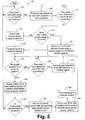
reading devices 18, thereading devices 18 read the data from each respective track. As the data is read from the magnetic strip, the data and clock from each track is serially transmitted to a serial-to-parallel converter 85. The serial-to-parallel converter 85 converts the data to parallel data words through techniques well known in the art. Then, inblock 107 ofFig. 5 , thecontrol mechanism 45 determines when a new data word associated with any of the tracks is defined and, therefore, ready to be transmitted. - In the preferred embodiment, each of the serial-to-
parallel converters 85 of thedata handlers 42 transmits a notification signal to thecontrol mechanism 45 when enough bits have been received to define a new data word. When a new data word is defined, thecontrol mechanism 45 instructs the serial-to-parallel converter 85 associated with the new data word to transmit the new data word to the data register 88 coupled to this serial-to-parallel converter, as shown byblocks blocks register 88. In the preferred embodiment, thecontrol mechanism 45 transmits a command signal to a serial-to-parallel converter 85 to instruct the serial-to-parallel converter 85 to transmit its newly defined data word. In response, the serial-to-parallel converter 85 transmits the new data word to itsrespective holding register 88. However, other methodologies for controlling the operation of the serial-to-parallel converters 85 are possible. - After transmitting at least one command signal to the serial-to-
parallel converters 85, thecontrol mechanism 45 selects one of thedata handlers 42. If there is only onedata handler 42 ready to transmit a data word at this point (i.e., has a data word in the holdingregister 88 associated with the data handler 42), thecontrol mechanism 45 selects the onedata handler 42, as depicted byblocks data handler 42 ready to transmit a data word, then thecontrol mechanism 45 selects one of thedata handlers 42 ready to transmit a data word based on thepredefined priority scheme 92, as shown byblocks 114 and 118. - As an example, assume that all three
data handlers 42 are simultaneously ready to transmit a respective data word inblock 114. Since thedata handler 42 that is associated with track 3 (i.e., that receives the data read from track 3) has the highest priority according to thepredefined priority scheme 92, thecontrol mechanism 45 selects thedata handler 42 that is associated with track 3. - Once the
control mechanism 45 selects one of thedata handlers 42 inblock 116 or 118, thecontrol mechanism 45 transmits an interrupt signal, or other type of notification signal, tocomputer system 37 to notify thecomputer system 37 that theinterfacing system 40 is ready to transmit a data word, as shown byblock 124. Then, thecontrol mechanism 45 waits for thecomputer system 37 to transmit a reply signal indicating that thecomputer system 37 is ready to receive a data word, as depicted by block 137. - While the
control mechanism 45 is waiting to receive the reply signal from thecomputer system 37, thecontrol mechanism 45 determines whether any new data words have been defined by any of the serial-to-parallel converters 85, as shown byblock 129. If there have been, thecontrol mechanism 45 transmits a command signal to the appropriate serial-to-parallel converter 85 to cause the serial-to-parallel converter 85 to transmit the new data word to itsrespective holding register 88, as shown byblock 131. This helps to prevent data overruns in the serial-to-parallel converters 85 from occurring while thecontrol mechanism 45 is waiting for a reply from thecomputer system 37. However, if a data overrun does occur, the serial-to-parallel converter 85 preferably detects this event and transmits a notification signal to thecontrol mechanism 45 indicating that a data overrun has occurred. In response, thecontrol mechanism 45 transmits an interrupt signal, or other type of notification signal, to thecomputer system 37 to indicate the occurrence of the overrun. - Once the reply signal from the
computer system 37 is received by thecontrol mechanism 45, the data word associated with the selected data handler 42 (i.e., thedata handler 42 processing data from track 3 in the example described hereinabove) is transmitted to thecomputer system 37, as depicted byblock 134. In preferred embodiment, thecontrol mechanism 45 transmits a command signal to the holdingregister 88 of the selecteddata handler 42 in response to the reply signal. The holdingregister 88, in response to the command signal, transmits a data word (i.e., signal 47) to themultiplexer 52. Themultiplexer 52, based on control signals from thecontrol mechanism 45, transmits the data word from the holdingregister 88 of the selecteddata handler 42 to thecomputer system 37. - Once the data word is transmitted to the
computer system 37, thecontrol mechanism 45 then determines inblock 136 whether there are anydata handlers 42 ready to transmit a data word. Note that the data words ready to be transmitted can include the data words identified inblocks block 111. As a result, thedata handlers 42 associated withtracks 1 and 2 have a respective data word ready to be transmitted. Therefore, thecontrol mechanism 45 defines anew priority scheme 95, as shown byblock 139. - In this regard, the
control mechanism 45 modifies the current priority scheme (i.e., the priority scheme most recently used to select adata handler 42 inblocks last data handler 42 to transmit a data word to thecomputer system 37 is assigned the lowest priority. Therefore, according to thenew priority scheme 95 in the foregoing example, thedata handler 42 associated withtrack 1 has the highest priority, thedata handler 42 associated with track 2 has the next highest priority, and thedata handler 42 associated with track 3 has the lowest priority. - Based on this
new priority scheme 95, thecontrol mechanism 45 selects thedata handler 42 that has the highest priority of thedata handlers 42 that are ready to transmit a data word to thecomputer system 37. Therefore, in the foregoing example, thecontrol mechanism 45 selects thedata handler 42 associated withtrack 1 inblock 142. Then, similar to block 124, thecontrol mechanism 45 in block 144 transmits an interrupt signal, or other type of notification signal, tocomputer system 37 to notify thecomputer system 37 that theinterfacing system 40 is ready to transmit a data word. Then, thecontrol mechanism 45 returns to block 137. As a result, a data word is transmitted from thedata handler 42 associated withtrack 1 to thecomputer system 37 via blocks 137-134. - Assuming that no new data words have been defined since
block 111, thedata handler 42 associated with track 2 is now theonly data handler 42 with a data word to be transmitted. As a result, thenew priority scheme 95 is modified inblock 139 such that thedata handler 42 associated with track 2 has the highest priority, the data handler associated with track 3 has the next highest priority, and thedata handler 42 associated withtrack 1 has the lowest priority. Inblock 142, thecontrol mechanism 45 selects thedata handler 42 associated with track 2 based on thisnew priority scheme 95 and returns toblocks 124 and 137. As a result, a data word from thedata handler 42 associated with track 2 is transmitted to thecomputer system 37 via blocks 137-134. - Assuming that no new data words have been defined since
block 111, none of thedata handlers 42 now have a data word ready to be transmitted. Therefore, thecontrol mechanism 45 returns to block 107, and the foregoing process is repeated. - It should be noted that blocks 124-131 are not necessary for implementation of the present invention. In this regard, it is possible for the
interfacing system 40 to transmit data words to thecomputer system 37 without waiting for a reply signal from thecomputer system 37. However, withoutblocks 124 and 137, thecomputer system 37 will be unable to control when the data words are transmitted to thecomputer system 37. This lack of control by thecomputer system 37 is undesirable in many applications. - Furthermore, although the
priority schemes priority schemes predefined priority scheme 92, if desired. - In addition, although the preferred embodiment depicts three
reading devices 18, the present invention should not be so limited. Any number (one or more) ofreading devices 18 andcorresponding data handlers 42 may be employed without departing from the principles of the present invention.
Claims (9)
- A system (40) for interfacing data from magnetic strips, comprising:a magnetic strip interface (18) configured to read data from a first track and a second track of a magnetic strip and to transmit the data;a first data handler (42) coupled to said magnetic strip interface, said first data handler (42) configured to receive the data read from the first track and to define a first data word based on the data read from the first track, said first data handler (42) further configured to transmit the first data word in response to a first command signal;a second data handler (42) coupled to said magnetic strip interface, said second data handler (42) configured to receive the data read from the second track and to define a second data word based on the data read from the second track, said second data handler (42) further configured to transmit the second data word in response to a second command signal; anda control mechanism (45) configured to transmit the first command signal and the second command signal;characterised by said control mechanism (45) being further configured to control when the first command signal and the second command signal are respectively transmitted to said first data handler (42) and said second data handler (42) based on a priority scheme.
- The system (40) of claim 1, wherein said control mechanism (45) is configured to receive a notification signal and to transmit at least one of the first command signal and the second command signal in response to the notification signal.
- The system of claim 1, further comprising a multiplexer (52) coupled to said first and second data handlers (42), said multiplexer (52) configured to receive the first and second data words and to transmit the first and second data words based on control signals, wherein said control mechanism (45) is further configured to transmit the control signals.
- The system of claim 1, wherein the priority scheme is based the amount of data included in the first track and based on the amount of data included in the second track.
- The system (40) of claim 1, wherein the priority scheme indicates that the first track has a higher priority than the second track, and wherein said control mechanism (45) is further configured to change the priority scheme such that the first track has a lower priority than the second track after the first data word has been transmitted by said first data handler (42).
- A method for interfacing data from magnetic strips, comprising the steps of:reading data from a first track of a magnetic strip;reading data from a second track of a magnetic strip;converting the data from the first track into a first data word;converting the data from the second track into a second data word;transmitting the first data word;transmitting the second data word; andselectively controlling which of said transmitting steps to perform first based on a priority scheme.
- The method of claim 6, where the priority scheme is based on the amount of data included in the first track and the amount of data included in the second track.
- The method of claim 6, wherein the priority scheme indicates that the most recently transmitted data word has the lowest priority.
- The method of claim 6, further comprising the steps of:receiving a signal;indicating with the signal that a computer system is ready to receive data; andperforming one of said transmitting steps in response to the signal.
Applications Claiming Priority (2)
| Application Number | Priority Date | Filing Date | Title |
|---|---|---|---|
| US09/294,239 US6233104B1 (en) | 1999-04-19 | 1999-04-19 | System and method for interfacing data stored on a magnetic strip |
| US294239 | 1999-04-19 |
Publications (3)
| Publication Number | Publication Date |
|---|---|
| EP1047013A2 EP1047013A2 (en) | 2000-10-25 |
| EP1047013A3 EP1047013A3 (en) | 2002-08-28 |
| EP1047013B1 true EP1047013B1 (en) | 2008-03-26 |
Family
ID=23132505
Family Applications (1)
| Application Number | Title | Priority Date | Filing Date |
|---|---|---|---|
| EP00301178A Expired - Lifetime EP1047013B1 (en) | 1999-04-19 | 2000-02-16 | System and method for interfacing data stored on a magnetic strip |
Country Status (3)
| Country | Link |
|---|---|
| US (1) | US6233104B1 (en) |
| EP (1) | EP1047013B1 (en) |
| DE (1) | DE60038406D1 (en) |
Families Citing this family (2)
| Publication number | Priority date | Publication date | Assignee | Title |
|---|---|---|---|---|
| US7809021B2 (en) | 2002-07-10 | 2010-10-05 | Solarflare Communications, Inc. | Communication system and encoding method having low overhead |
| JP4957889B2 (en) * | 2006-08-29 | 2012-06-20 | 株式会社エクォス・リサーチ | Traveling vehicle |
Family Cites Families (6)
| Publication number | Priority date | Publication date | Assignee | Title |
|---|---|---|---|---|
| JPS5165915A (en) * | 1974-12-04 | 1976-06-08 | Fujitsu Ltd | Toratsukukanisozurehoshohoshiki |
| DE2714833C2 (en) * | 1977-04-02 | 1982-09-23 | Philips Patentverwaltung Gmbh, 2000 Hamburg | Arrangement to compensate for the skew when reading a magnetic account card |
| US4680732A (en) * | 1982-07-23 | 1987-07-14 | Ncr Corporation | Interface circuit for connecting peripheral equipment to a computer terminal |
| US4794642A (en) * | 1987-09-24 | 1988-12-27 | American Telephone And Telegraph Company, At&T Bell Laboratories | Call screening in a public telephone station |
| MY106779A (en) * | 1990-09-07 | 1995-07-31 | Mitsubishi Heavy Ind Ltd | Magnetic recording method and circuit for toll road ticket. |
| JP2962627B2 (en) * | 1993-01-20 | 1999-10-12 | 沖電気工業株式会社 | Magnetic data reader |
-
1999
- 1999-04-19 US US09/294,239 patent/US6233104B1/en not_active Expired - Fee Related
-
2000
- 2000-02-16 DE DE60038406T patent/DE60038406D1/en not_active Expired - Lifetime
- 2000-02-16 EP EP00301178A patent/EP1047013B1/en not_active Expired - Lifetime
Also Published As
| Publication number | Publication date |
|---|---|
| EP1047013A2 (en) | 2000-10-25 |
| US6233104B1 (en) | 2001-05-15 |
| DE60038406D1 (en) | 2008-05-08 |
| EP1047013A3 (en) | 2002-08-28 |
Similar Documents
| Publication | Publication Date | Title |
|---|---|---|
| EP0206083B1 (en) | Method and apparatus for interfacing buses of different sizes | |
| US5175732A (en) | Method and apparatus for controlling data communication operations within stations of a local-area network | |
| US20100088454A1 (en) | Bridging device with power-saving function | |
| EP3001323A1 (en) | Serial peripheral interface | |
| WO2001091046A1 (en) | Ic card | |
| US20060010279A1 (en) | Apparatus for use in a computer systems | |
| US6233104B1 (en) | System and method for interfacing data stored on a magnetic strip | |
| HK36994A (en) | Apparatus for read handshake in high-speed asynchronous bus interface | |
| US5228129A (en) | Synchronous communication interface for reducing the effect of data processor latency | |
| CA2723056C (en) | Multimedia card interface method, computer program product and apparatus | |
| US5247640A (en) | Dual access control system including plural magnetic disk control units and contention control circuitry | |
| JP2001127827A (en) | Data transfer system | |
| US20050144338A1 (en) | Data transfer apparatus | |
| EP2026214A1 (en) | Data transfer device, request issuing unit, and request issuing method | |
| KR0146090B1 (en) | High speed data transmitting system for processing image | |
| US20030061429A1 (en) | Synchronizer for processor facility and PCMCIA card | |
| EP0609082A1 (en) | Information transfer in a data processing system | |
| JPH11298450A (en) | Serial data transfer controller | |
| EP0609083A1 (en) | Information transfer in a data processing system | |
| JPH023343B2 (en) | ||
| JPH06309272A (en) | Memory access method | |
| JPH0911585A (en) | Printer device and control method for automatically switching a plurality of I / Fs | |
| ZA200704397B (en) | Multimedia card interface method, computer program product and apparatus | |
| JPH0279645A (en) | System for controlling delimiter of communication control equipment | |
| JPH0495122A (en) | Terminal controller |
Legal Events
| Date | Code | Title | Description |
|---|---|---|---|
| PUAI | Public reference made under article 153(3) epc to a published international application that has entered the european phase |
Free format text: ORIGINAL CODE: 0009012 |
|
| AK | Designated contracting states |
Kind code of ref document: A2 Designated state(s): AT BE CH CY DE DK ES FI FR GB GR IE IT LI LU MC NL PT SE |
|
| AX | Request for extension of the european patent |
Free format text: AL;LT;LV;MK;RO;SI |
|
| RAP1 | Party data changed (applicant data changed or rights of an application transferred) |
Owner name: AGILENT TECHNOLOGIES INC. |
|
| RAP1 | Party data changed (applicant data changed or rights of an application transferred) |
Owner name: AGILENT TECHNOLOGIES INC. A DELAWARE CORPORATION |
|
| RAP1 | Party data changed (applicant data changed or rights of an application transferred) |
Owner name: AGILENT TECHNOLOGIES, INC. (A DELAWARE CORPORATION |
|
| PUAL | Search report despatched |
Free format text: ORIGINAL CODE: 0009013 |
|
| AK | Designated contracting states |
Kind code of ref document: A3 Designated state(s): AT BE CH CY DE DK ES FI FR GB GR IE IT LI LU MC NL PT SE |
|
| AX | Request for extension of the european patent |
Free format text: AL;LT;LV;MK;RO;SI |
|
| 17P | Request for examination filed |
Effective date: 20030203 |
|
| AKX | Designation fees paid |
Designated state(s): DE FR GB |
|
| 17Q | First examination report despatched |
Effective date: 20050822 |
|
| RAP1 | Party data changed (applicant data changed or rights of an application transferred) |
Owner name: AVAGO TECHNOLOGIES GENERAL IP (SINGAPORE) PTE. LTD |
|
| GRAP | Despatch of communication of intention to grant a patent |
Free format text: ORIGINAL CODE: EPIDOSNIGR1 |
|
| GRAS | Grant fee paid |
Free format text: ORIGINAL CODE: EPIDOSNIGR3 |
|
| GRAA | (expected) grant |
Free format text: ORIGINAL CODE: 0009210 |
|
| AK | Designated contracting states |
Kind code of ref document: B1 Designated state(s): DE FR GB |
|
| REG | Reference to a national code |
Ref country code: GB Ref legal event code: FG4D |
|
| REF | Corresponds to: |
Ref document number: 60038406 Country of ref document: DE Date of ref document: 20080508 Kind code of ref document: P |
|
| EN | Fr: translation not filed | ||
| PG25 | Lapsed in a contracting state [announced via postgrant information from national office to epo] |
Ref country code: DE Free format text: LAPSE BECAUSE OF FAILURE TO SUBMIT A TRANSLATION OF THE DESCRIPTION OR TO PAY THE FEE WITHIN THE PRESCRIBED TIME-LIMIT Effective date: 20080627 |
|
| PLBE | No opposition filed within time limit |
Free format text: ORIGINAL CODE: 0009261 |
|
| STAA | Information on the status of an ep patent application or granted ep patent |
Free format text: STATUS: NO OPPOSITION FILED WITHIN TIME LIMIT |
|
| 26N | No opposition filed |
Effective date: 20081230 |
|
| PG25 | Lapsed in a contracting state [announced via postgrant information from national office to epo] |
Ref country code: FR Free format text: LAPSE BECAUSE OF FAILURE TO SUBMIT A TRANSLATION OF THE DESCRIPTION OR TO PAY THE FEE WITHIN THE PRESCRIBED TIME-LIMIT Effective date: 20090116 |
|
| GBPC | Gb: european patent ceased through non-payment of renewal fee |
Effective date: 20090216 |
|
| PG25 | Lapsed in a contracting state [announced via postgrant information from national office to epo] |
Ref country code: GB Free format text: LAPSE BECAUSE OF NON-PAYMENT OF DUE FEES Effective date: 20090216 |