EP1046549A2 - Faltverfahren für einen Luftsack - Google Patents
Faltverfahren für einen Luftsack Download PDFInfo
- Publication number
- EP1046549A2 EP1046549A2 EP00108009A EP00108009A EP1046549A2 EP 1046549 A2 EP1046549 A2 EP 1046549A2 EP 00108009 A EP00108009 A EP 00108009A EP 00108009 A EP00108009 A EP 00108009A EP 1046549 A2 EP1046549 A2 EP 1046549A2
- Authority
- EP
- European Patent Office
- Prior art keywords
- folding
- holding plate
- center line
- parallel
- folded
- Prior art date
- Legal status (The legal status is an assumption and is not a legal conclusion. Google has not performed a legal analysis and makes no representation as to the accuracy of the status listed.)
- Withdrawn
Links
- 238000000034 method Methods 0.000 title claims description 19
- 239000004744 fabric Substances 0.000 claims abstract description 17
- 238000004804 winding Methods 0.000 claims abstract description 3
- 238000009434 installation Methods 0.000 description 4
- 239000002360 explosive Substances 0.000 description 2
- 239000000463 material Substances 0.000 description 2
- 240000006240 Linum usitatissimum Species 0.000 description 1
- 206010040954 Skin wrinkling Diseases 0.000 description 1
- 230000001427 coherent effect Effects 0.000 description 1
- 230000003111 delayed effect Effects 0.000 description 1
- 238000004519 manufacturing process Methods 0.000 description 1
Images
Classifications
-
- B—PERFORMING OPERATIONS; TRANSPORTING
- B60—VEHICLES IN GENERAL
- B60R—VEHICLES, VEHICLE FITTINGS, OR VEHICLE PARTS, NOT OTHERWISE PROVIDED FOR
- B60R21/00—Arrangements or fittings on vehicles for protecting or preventing injuries to occupants or pedestrians in case of accidents or other traffic risks
- B60R21/02—Occupant safety arrangements or fittings, e.g. crash pads
- B60R21/16—Inflatable occupant restraints or confinements designed to inflate upon impact or impending impact, e.g. air bags
- B60R21/23—Inflatable members
- B60R21/237—Inflatable members characterised by the way they are folded
Definitions
- the invention relates to a method for folding an airbag for a in the steering wheel Motor vehicle arranged airbag module, which consists of two approximately circular fabric sections exists, which are connected to one another at the edge, and in the middle of a tissue section has a gas inlet and mounting opening with retaining plate, one of a pot-like Lower part and a lid-like upper part is limited receiving volume.
- One of the purposes of such folding processes is to keep the airbag fabric as small as possible To reduce volume, which often complicates the fact that the available installation space is not coherent, but more or less dissected, because it also contains other parts of the Airbag module must be accommodated or because the installation environment is no different Admits volume.
- a second important aspect when folding an airbag is the inflation behavior, which can be influenced within certain limits by the manner of folding is. Of course, the explosive inflation of the airbag due to the type of folding cannot be prevented or delayed inadmissibly. On the other hand, the type and Influence the way that the airbag does not unfold too quickly or that the unfolding preferably first transversely to the direction of impact and only then in the direction of impact he follows.
- the invention has for its object a method of the type mentioned to propose in which all of the above conditions are met, especially for in Steering wheels to be arranged airbag modules is suitable.
- the folding method according to the invention is very simple, because with the zigzag or just watch out for meandering folding along folding edges that are parallel to each other must be that the individual folded layers have the same height. Since the folding positions are vertical are arranged to the level of the holding plate, it is easily possible to determine the height of the finished Adapt the folding package to the height of the available installation space. Since this installation space Airbag modules, which are installed in steering wheels, to the driver through a cover cap is limited, which is adapted to the steering wheel environment and for actuating the horn contact is formed, it is expedient if the cover cap in the folded air bag over its entire surface abutment is found so that it itself is not too rigid and must be self-supporting, which hinders the deployment of the airbag could. Since the height of the folded positions can be freely selected in the method according to the invention one also the requirement for a reliable abutment for the cover cap easily meet changing boundary conditions.
- the vertically arranged folding layers In comparison with folding layers arranged parallel to the holding plate or to the cover cap, the vertically arranged folding layers also have the advantage that they are much more elastic Form abutments, which is advantageous for those impact situations below the Response threshold for the deployment of the airbag are. It can also make the required Mobility of the cap for actuating the horn contact can be realized more easily.
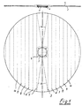
- 1 and 2 are circular fabric sections, which are flat one above the other are spread out, the fabric section 2 with the gas inlet and assembly opening 3rd lies down. Between the two circular fabric sections 1 and 2 there is a holding plate 4 arranged, which serves to attach the airbag in the airbag module.
- 5 to 10 are the first Fold lines that run parallel to a center line and along which the Airbag fabric is folded zigzag or meandering.
- the airbag fabric above and below the retaining plate 4 is also approximately longitudinal the oblique fold lines 5a folded.
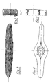
- the entire fabric material is on the Gas inlet and mounting opening 3 opposite side of the gas bag arranged and over the width of the holding plate 4 is folded in a plurality of folded positions of the same height, all folding positions are arranged perpendicular to the plane of the holding plate 4.
- the fabric material of the airbag is open the side of the gas inlet and mounting opening 3, which in turn is perpendicular the plane of the holding plate standing folding positions in the area of the gas inlet and assembly opening 3rd are spaced from each other and form a space for receiving a gas generator. It it should be pointed out that to clarify the exact course of the folding The transverse dimensions of the folded positions are shown enlarged.
- the folding forms according to FIGS. 3 and 5 are then turned perpendicular to the holding plate 4 standing axis wrapped or folded, whereby the entire folding package to the existing Recording volume is adjusted.
- the height of the folded layers can be chosen freely with this method be, so that it is easily possible to the finished folding package to the height of the existing one Adjust the recording volume.
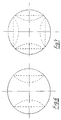
- FIGS. 6 and 7 two other possible starting forms can be seen, which are represented by Inverting edge areas along parallel and / or perpendicular to the center line Folded edges can be reached. These starting forms are for carrying out the invention Process just as suitable as the starting form according to Figure 1. In all cases, the height of the folding positions freely chosen, and the folding packs according to FIGS. 3 and 5 can be wound or Folding processes to be adapted to the existing volume.
Landscapes
- Engineering & Computer Science (AREA)
- Mechanical Engineering (AREA)
- Air Bags (AREA)
Abstract
Description
Claims (7)
- Verfahren zum Falten eines Luftsacks für ein im Lenkrad eines Kraftfahrzeuges angeordnetes Airbag-Modul, der aus zwei etwa kreisförmigen Gewebeabschnitten besteht, die randseitig miteinander verbunden sind, und der in der Mitte eines Gewebeabschnitts eine Gaseinlaß- und Montageöffnung mit Halteblech aufweist, wobei ein von einem topfartigen Unterteil und einem deckelartigen Oberteil begrenztes Aufnahmevolumen vorgegeben ist, gekennzeichnet durch folgende Schritte:(1) die beiden kreisförmigen Gewebeabschnitte werden flach übereinanderliegend so ausgebreitet, daß sie in eine Ebene parallel zum Halteblech liegen,(2) die links und rechts von einer Mittellinie liegenden Hälften der übereinanderliegenden Gewebeabschnitte werden längs parallel zur Mittellinie verlaufender Faltlinien zu zwei auf der der Gaseinlaßöffnung gegenüberliegenden Seite angeordneten, langgestreckten, unmittelbar nebeneinander liegenden Paketen aufgefaltet, deren einzelne Faltlagen im wesentlichen die gleiche Höhe aufweisen und senkrecht zum Halteblech angeordnet sind,(3) die beiden langgestreckten Pakte werden um senkrecht zum Halteblech verlaufende Achsen durch Falten und/oder Wickeln an das Aufnahmevolumen angepaßt.
- Verfahren nach Anspruch 1, jedoch mit der Maßgabe, daß im zweiten Schritt die links und rechts von der Mittellinie liegenden Hälften der übereinanderliegenden Gewebeabschnitte längs parallel zur Mittellinie verlaufender Faltlinien zu zwei auf der Gaseinlaßseite liegenden, langgestreckten Paketen aufgefaltet werden, die im Bereich der Gaseinlaßöffnung voneinander beabstandet sind und einen Freiraum für die Anordnung eines Gasgenerators aufweisen.
- Verfahren nach Anspruch 1 oder 2, dadurch gekennzeichnet, daß die Pakete im dritten Schritt je für sich gefaltet bzw. gewickelt werden.
- Verfahren nach Anspruch 1 oder 2, dadurch gekennzeichnet, daß die Pakete im dritten Schritt gemeinsam gefaltet bzw. gewickelt werden.
- Verfahren nach einem der Ansprüche 1 bis 4, dadurch gekennzeichnet, daß vor dem ersten Schritt die außenliegenden Gewebeabschnitte parallel zur Mittellinie eingestülpt werden, so daß eine Ausgangsform mit zwei zueinander parallelen, geraden Rändern und dazwischenliegenden Rändern in Form von Kreisbogenabschnitten entsteht.
- Verfahren nach einem der Ansprüche 1 bis 4, dadurch gekennzeichnet, daß vor dem ersten Schritt die außenliegenden Gewebeabschnitte parallel und senkrecht zur Mittellinie eingestülpt werden, so daß eine im wesentlichen quadratische Ausgangsform entsteht.
- Verfahren nach Anspruch 5 oder 6, dadurch gekennzeichnet, daß die eingestülpten Bereiche ein- oder mehrfach bis zur jeweils vorausgehenden Stülpkante zurückgestülpt werden.
Applications Claiming Priority (2)
| Application Number | Priority Date | Filing Date | Title |
|---|---|---|---|
| DE19918584A DE19918584A1 (de) | 1999-04-23 | 1999-04-23 | Faltverfahren für einen Luftsack |
| DE19918584 | 1999-04-23 |
Publications (2)
| Publication Number | Publication Date |
|---|---|
| EP1046549A2 true EP1046549A2 (de) | 2000-10-25 |
| EP1046549A3 EP1046549A3 (de) | 2000-11-29 |
Family
ID=7905691
Family Applications (1)
| Application Number | Title | Priority Date | Filing Date |
|---|---|---|---|
| EP00108009A Withdrawn EP1046549A3 (de) | 1999-04-23 | 2000-04-19 | Faltverfahren für einen Luftsack |
Country Status (3)
| Country | Link |
|---|---|
| EP (1) | EP1046549A3 (de) |
| JP (1) | JP2000313298A (de) |
| DE (1) | DE19918584A1 (de) |
Family Cites Families (4)
| Publication number | Priority date | Publication date | Assignee | Title |
|---|---|---|---|---|
| JPH0657520B2 (ja) * | 1986-02-28 | 1994-08-03 | 本田技研工業株式会社 | エアバツクの折り畳み方法 |
| DE19502744C1 (de) * | 1995-01-18 | 1996-03-21 | Petri Ag Niederlassung Berlin | Gassack für einen Airbagmodul und Verfahren zur Faltung des Gassackes |
| US6170870B1 (en) * | 1996-01-29 | 2001-01-09 | Petri Ag | Airbag for airbag module and method for folding airbag |
| JPH1044900A (ja) * | 1996-08-02 | 1998-02-17 | Sensor Technol Kk | エアバッグの折り畳み方法 |
-
1999
- 1999-04-23 DE DE19918584A patent/DE19918584A1/de not_active Withdrawn
-
2000
- 2000-04-19 EP EP00108009A patent/EP1046549A3/de not_active Withdrawn
- 2000-04-24 JP JP2000121995A patent/JP2000313298A/ja not_active Withdrawn
Non-Patent Citations (1)
| Title |
|---|
| None |
Also Published As
| Publication number | Publication date |
|---|---|
| DE19918584A1 (de) | 2000-10-26 |
| EP1046549A3 (de) | 2000-11-29 |
| JP2000313298A (ja) | 2000-11-14 |
Similar Documents
| Publication | Publication Date | Title |
|---|---|---|
| DE19848592B4 (de) | Airbag mit Abschirmung | |
| EP0897837B1 (de) | Verfahren zum Falten eines Gassackes einer Aufprallschutzvorrichtung | |
| EP1681209B1 (de) | Seitenairbageinrichtung | |
| EP0850160B1 (de) | Verfahren und vorrichtung zur faltung eines gassackes für ein airbagmodul | |
| DE4220825C2 (de) | Gefaltetes Gaskissen | |
| DE4422276C2 (de) | Gassack, Verfahren zu seiner Faltung und Vorrichtung zur Durchführung des Faltverfahrens | |
| DE19806301A1 (de) | Airbag mit Expansionshemmer | |
| DE19641641A1 (de) | Airbagmodul mit vereinfachter Kissenbefestigung | |
| EP1043195B1 (de) | Faltverfahren für den Luftsack eines Seitenairbags | |
| EP0865972A2 (de) | Gassack | |
| DE19860932A1 (de) | Airbagmodul | |
| DE2529602C2 (de) | Aufblasbarer Schutzsack einer Fahrzeugsicherheitsvorrichtung und Verfahren zu seiner Herstellung | |
| EP1149741A2 (de) | Faltverfahren und -vorrichtung | |
| DE4408037C2 (de) | Aufprallschutzeinrichtung für einen Insassen eines Kraftfahrzeuges | |
| EP1896299B1 (de) | Gassackanordnung für ein airbagmodul eines kraftfahrzeugs | |
| DE19523336A1 (de) | Gefalteter Airbag | |
| EP0877682B1 (de) | Gassack für ein airbagmodul und verfahren zur faltung des gassackes | |
| EP0622275A2 (de) | Verfahren zum Falten eines Luftsackes | |
| DE19502744C1 (de) | Gassack für einen Airbagmodul und Verfahren zur Faltung des Gassackes | |
| DE10039555B4 (de) | Gassack und Verfahren zur Herstellung eines Gassackes | |
| EP1062126A1 (de) | Airbagmodul, insbesondere beifahrerairbagmodul | |
| DE4214662C2 (de) | Aufprallschutzeinrichtung für einen Insassen eines Kraftfahrzeuges | |
| DE2827994C3 (de) | Verpackung für stoßempfindliche Güter, z.B. elektrische oder mechanische Geräte, insbesondere für Autoradios | |
| DE102021122900A1 (de) | Lenkrad mit einem gassack | |
| DE19519998C2 (de) | Beifahrerairbagmodul |
Legal Events
| Date | Code | Title | Description |
|---|---|---|---|
| PUAI | Public reference made under article 153(3) epc to a published international application that has entered the european phase |
Free format text: ORIGINAL CODE: 0009012 |
|
| PUAL | Search report despatched |
Free format text: ORIGINAL CODE: 0009013 |
|
| AK | Designated contracting states |
Kind code of ref document: A2 Designated state(s): AT BE CH CY DE DK ES FI FR GB GR IE IT LI LU MC NL PT SE |
|
| AX | Request for extension of the european patent |
Free format text: AL;LT;LV;MK;RO;SI |
|
| AK | Designated contracting states |
Kind code of ref document: A3 Designated state(s): AT BE CH CY DE DK ES FI FR GB GR IE IT LI LU MC NL PT SE |
|
| AX | Request for extension of the european patent |
Free format text: AL;LT;LV;MK;RO;SI |
|
| AKX | Designation fees paid | ||
| REG | Reference to a national code |
Ref country code: DE Ref legal event code: 8566 |
|
| STAA | Information on the status of an ep patent application or granted ep patent |
Free format text: STATUS: THE APPLICATION IS DEEMED TO BE WITHDRAWN |
|
| 18D | Application deemed to be withdrawn |
Effective date: 20010630 |