EP1046457A1 - Device for transfer to a work station of items to be assembled - Google Patents
Device for transfer to a work station of items to be assembled Download PDFInfo
- Publication number
- EP1046457A1 EP1046457A1 EP99107967A EP99107967A EP1046457A1 EP 1046457 A1 EP1046457 A1 EP 1046457A1 EP 99107967 A EP99107967 A EP 99107967A EP 99107967 A EP99107967 A EP 99107967A EP 1046457 A1 EP1046457 A1 EP 1046457A1
- Authority
- EP
- European Patent Office
- Prior art keywords
- carousel
- carrier element
- carriage
- roller
- notch
- Prior art date
- Legal status (The legal status is an assumption and is not a legal conclusion. Google has not performed a legal analysis and makes no representation as to the accuracy of the status listed.)
- Granted
Links
Images


Classifications
-
- G—PHYSICS
- G04—HOROLOGY
- G04D—APPARATUS OR TOOLS SPECIALLY DESIGNED FOR MAKING OR MAINTAINING CLOCKS OR WATCHES
- G04D1/00—Gripping, holding, or supporting devices
- G04D1/005—Gripping, holding, or supporting devices for non-automatic assembly, with automatic transport between workbenches
- G04D1/0064—Turntables or plates (carousels)
-
- B—PERFORMING OPERATIONS; TRANSPORTING
- B23—MACHINE TOOLS; METAL-WORKING NOT OTHERWISE PROVIDED FOR
- B23P—METAL-WORKING NOT OTHERWISE PROVIDED FOR; COMBINED OPERATIONS; UNIVERSAL MACHINE TOOLS
- B23P19/00—Machines for simply fitting together or separating metal parts or objects, or metal and non-metal parts, whether or not involving some deformation; Tools or devices therefor so far as not provided for in other classes
- B23P19/001—Article feeders for assembling machines
-
- B—PERFORMING OPERATIONS; TRANSPORTING
- B23—MACHINE TOOLS; METAL-WORKING NOT OTHERWISE PROVIDED FOR
- B23Q—DETAILS, COMPONENTS, OR ACCESSORIES FOR MACHINE TOOLS, e.g. ARRANGEMENTS FOR COPYING OR CONTROLLING; MACHINE TOOLS IN GENERAL CHARACTERISED BY THE CONSTRUCTION OF PARTICULAR DETAILS OR COMPONENTS; COMBINATIONS OR ASSOCIATIONS OF METAL-WORKING MACHINES, NOT DIRECTED TO A PARTICULAR RESULT
- B23Q7/00—Arrangements for handling work specially combined with or arranged in, or specially adapted for use in connection with, machine tools, e.g. for conveying, loading, positioning, discharging, sorting
- B23Q7/02—Arrangements for handling work specially combined with or arranged in, or specially adapted for use in connection with, machine tools, e.g. for conveying, loading, positioning, discharging, sorting by means of drums or rotating tables or discs
Definitions
- the present invention relates to a device for bringing one after the other a plurality of small objects at a work station served by an operator responsible in particular for manually assembling minus a component on said objects.
- the description of such workstations is known from several documents.
- the document CH 596 062 shows for example a series of elements rectangular carriers which each support a part to be assembled, these load-bearing elements which can move along perpendicular axes between them and this parallel and perpendicular to the longitudinal direction an assembly line, this is a heavy, bulky system and difficult to transport. It should also be noted that the exhibits assemble are integral with a chain which, once loaded, is very difficult to modify. If a change still needs to be made, you will have to move the entire device or move all the pieces one by one placed on the load-bearing elements. Finally, there is no provision in this document to extract the workpiece from the chain that carries it, such so that adjacent parts can interfere with the operator.
- the document FR 1 248 779 describes a machine tool which comprises a table that can be brought in step by step, then locked angularly in different working positions. Workpiece carriers are arranged on the around the table and are brought successively opposite the pins toolholders. If it is obvious that such a system can be transposed to a system allowing the manual assembly of moving parts one after the other in front of an operator, this operator will be hampered by the parts located on either side of the work piece so that these pieces bordering will support the operator's wrists, which is avoid at all costs. Note also that the rotary table of the document cited is not removable and that to move to other parts to be assembled, it remove all parts from the table before replacing them with others.
- Figures 1 and 2 show the device of the invention in its idea the more general.
- a workstation 2 includes two armrests 25 and 26 on which the forearms of a operator. Between these armrests is the actual workstation where the object 1 ′ can undergo an intervention (FIG. 2), for example an adjustment or still the installation of at least one component, for example ice or needles.
- an intervention for example an adjustment or still the installation of at least one component, for example ice or needles.
- This device first comprises a circular carousel 3 moved by a first drive member 5 that can be seen in Figures 4 and 5.
- the carousel 5 carries in its peripheral zone a plurality of carrier elements 4 which seen in Figures 3, 4 and 5.
- These carrier elements 4 each carry a object 1 to which must be assembled, for example, a component.
- the device then comprises a carriage 6 driven by a second member motor 7 as can be seen in FIGS. 4 and 5.
- This carriage is arranged to enter one of the load-bearing elements 4 when this load-bearing element occupies a determined angular position suitable for bringing said element porter at work station 2.
- the device includes a control system symbolized on the Figures 1, 2 and 5 by a pusher 8.
- the pusher 8 can be actuated by the operator once the assembly operation is complete. This actuation brings back via the carriage 6, the carrier element 4 on the carousel 3, then what the carousel rotates until the next carrier element occupies the position specific angle suitable for bringing it to workstation 2 via the same carriage 6.
- the carousel 3 has in its peripheral area a plurality of first rectangular notches 13 arranged radially.
- the figures show twenty notches 13. There could be fewer, for example only two, or more, say twenty-five.
- Workstation 2 (figures 1, 2 and 5) has a plate 14 in which a second is practiced rectangular notch 15 whose width A is substantially equal to the width B of the first notches 13.
- the carrier element 4 consists of a roller 16 which has a recess 17 in the middle of its edge which gives it the appearance of a washer of yo-yo.
- the recess 17 is engaged either in one of the first notches 13 ( Figures 3 and 4) or in the second notch 17 according to that, respectively, the carrier element 4 is located on the carousel 3 or on the workstation 2.
- the trolley 6 has the mission to bring the carrier element 4, in this case the roller 16, from the position it occupies in solid lines on the carousel 3 in the position it occupies in lines dotted on the work station 2.
- the carriage 6 is provided with two let us hold 18 and 19 between which the roller 16 engages when the first notch 13 is located opposite the second notch 15.
- these tenons 18 and 19 are advantageously covered a layer of vibration absorbing material, for example formed of a section of silicone hose, threaded over these tenons, to eliminate vibrations during the transport of the load-bearing elements 4.
- a layer of vibration absorbing material for example formed of a section of silicone hose, threaded over these tenons, to eliminate vibrations during the transport of the load-bearing elements 4.
- the carrying element 4 ′ is then in position at the work station 2 where can be performed the intervention or interventions that should be undertaken on object 1 (not shown here).
- the determined angular position of the carousel 3 must be that for which one of the first notches 13 of said carousel 3 is an extension of the second notch 15 of the station working 2.
- FIG. 3 shows the carousel 3 outside the context of the machine.
- a watch 1 on which must be practiced a certain operation.
- This watch rests on a load-bearing element including the pebble 16 has been drawn in dotted lines.
- a supporting element 4 with its roller 16.
- the recess 17 is in the form of a circle 21.
- This arrangement allows the carrier element 4 to rotate on itself as well as object 1 that could overcome it. So when the object is brought to the post of work, does the operator have the leisure to bring it in different positions angles required by the interventions to be performed.
- a carrier element 4 with its roller 16 In the same figure 3 and to the left of watch 1, a carrier element 4 with its roller 16.
- the recess 17 is in the form of a square 22 making impossible rotation of the roller, the side of the square being substantially equal to the width B of the first notch 13.
- this roller arrives at the post work 2, we understand that it will be prevented from any rotation since the second notch 15 has a width B substantially equal to the width A of the first notch 13.
- This provision is intended for operations - for example setting up the watch hands - where it is imperative that the object is not allowed to rotate.
- Figures 3 and 6 show that the first notch 13 is provided a spring 20 to hold the carrier element in place 4.
- a cell 30 in the notch 13 a cell in which takes place a split spring of tubular shape 20.
- the spring 20 flexes and keeps said roller in place.
- the Figures 1 and 5 show that the second notch 15 located in the plate 14 of the workstation also carries a cell 30 in which takes place a spring 20 (not shown) to hold in place the carrier element 4 when it is at the bottom of this second cell.
- This holding in place is important especially to prevent objects from falling from the carousel 3 when transporting the latter. It is also important that the object at work be well kept in place when operating on it certain operations of mounting and / or adjustment.
- the carousel 3 is removably mounted on a plate 9 itself driven by a first drive member 5.
- the carousel is freely engaged on the shaft 31 of the plate 9.
- Plate 9 is provided with a pin 10 engaged in a hole 11 practiced in the carousel 3.
- This pin drives the rotating carousel.
- the first motor member 5 is of the stepping type capable of rotating the carousel 3 with one step (see figure 3) corresponding to the angle ⁇ which separates two neighboring load-bearing elements. This advance of one step takes place when the workpiece 1 '( Figure 2) returned to carousel 3 at the instigation of the control device 8.
- the first organ drives an endless screw 33 via a coupling 32.
- the screw 33 drives in turn a toothed wheel 34 which is integral with the shaft 31.
- the device comprises a second drive member 7 for bringing one of the carrier elements 4 to the work 2.
- This second motor member 7 also consists of a stepping motor.
- this second drive member 7 drives, by means of a coupling 35, a toothed belt 12 meshing with two toothed pulleys 36 and 37.
- the carriage 6 To this belt is attached the carriage 6 to convey by a back and forth movement, the carrier element 4 first at workstation 2, then at carousel 3.
- the device of the invention requires to be controlled by a small programmable computer controlled among others by different state sensors.
- this control system will allow for example the rapid rotation of the carousel of one or more steps in one direction or the other, the selection by the keyboard of the number of positions of the discs and the rotation of the carousel without entering load-bearing elements.
- This system may also include a total and daily counter with reset and search automatic machine references when switching on.
- the device will include at least one zero point detector of the carousel, a zero point detector of the carriage driving the element carrier and a detector of the presence of the carousel.
- the device described is particularly suitable for treating parts horology and, in general, small objects related to micromechanics.
Landscapes
- Engineering & Computer Science (AREA)
- Mechanical Engineering (AREA)
- Physics & Mathematics (AREA)
- General Physics & Mathematics (AREA)
- Automatic Assembly (AREA)
Abstract
Description
La présente invention est relative à un dispositif pour amener l'un après l'autre une pluralité d'objets de petites dimensions à un poste de travail desservi par un opérateur chargé notamment d'assembler manuellement au moins un composant sur lesdits objets.The present invention relates to a device for bringing one after the other a plurality of small objects at a work station served by an operator responsible in particular for manually assembling minus a component on said objects.
Il peut s'agir ici d'un poste de travail isolé ou d'un poste de travail associé à plusieurs autres insérés dans une chaíne d'assemblage. La description de tels postes de travail est connue de plusieurs documents.This can be an isolated workstation or a workstation associated with several others inserted in an assembly line. The description of such workstations is known from several documents.
Le document CH 596 062 montre par exemple une série d'éléments porteurs rectangulaires qui supportent chacun une pièce à assembler, ces éléments porteurs pouvant se déplacer selon des axes perpendiculaires entre eux et cela parallèlement et perpendiculairement à la direction longitudinale d'une chaíne d'assemblage, il s'agit là d'un système lourd, encombrant et difficilement transportable. On fera remarquer aussi que les pièces à assembler sont solidaires d'une chaíne qui, une fois chargée, est très difficilement modifiable. Si une modification doit être tout de même apportée, il faudra déplacer l'entier du dispositif ou déplacer une à une toutes les pièces posées sur les éléments porteurs. Enfin, il n'est nullement prévu dans ce document d'extraire la pièce à travailler de la chaíne qui la transporte, de telle sorte que les pièces voisines peuvent gêner l'opérateur.The document CH 596 062 shows for example a series of elements rectangular carriers which each support a part to be assembled, these load-bearing elements which can move along perpendicular axes between them and this parallel and perpendicular to the longitudinal direction an assembly line, this is a heavy, bulky system and difficult to transport. It should also be noted that the exhibits assemble are integral with a chain which, once loaded, is very difficult to modify. If a change still needs to be made, you will have to move the entire device or move all the pieces one by one placed on the load-bearing elements. Finally, there is no provision in this document to extract the workpiece from the chain that carries it, such so that adjacent parts can interfere with the operator.
Le document FR 1 248 779 décrit une machine outil qui comprend une table susceptible d'être amenée pas à pas, puis bloquée angulairement dans différentes positions de travail. Des porte-pièces sont disposés sur le pourtour de la table et sont amenés successivement vis-à-vis des broches porte-outils. S'il est évident qu'un tel système peut être transposé à un système permettant l'assemblage manuel de pièces défilant l'une après l'autre devant un opérateur, cet opérateur va être gêné par les pièces situées de part et d'autre de la pièce à travailler de telle sorte que ces pièces limitrophes serviront de support aux poignets de l'opérateur, ce qui est à éviter à tout prix. A remarquer également que la table rotative du document cité n'est pas amovible et que pour passer à d'autres pièces à assembler, il faudra enlever de la table toutes les pièces avant de les remplacer par d'autres.The document FR 1 248 779 describes a machine tool which comprises a table that can be brought in step by step, then locked angularly in different working positions. Workpiece carriers are arranged on the around the table and are brought successively opposite the pins toolholders. If it is obvious that such a system can be transposed to a system allowing the manual assembly of moving parts one after the other in front of an operator, this operator will be hampered by the parts located on either side of the work piece so that these pieces bordering will support the operator's wrists, which is avoid at all costs. Note also that the rotary table of the document cited is not removable and that to move to other parts to be assembled, it remove all parts from the table before replacing them with others.
Pour pallier les inconvénients cités ci-dessus, le dispositif de l'invention prévoit d'installer les objets à travailler sur un posage amovible, facile à remplacer, l'objet en travail étant sorti de ce posage pendant les opérations d'assemblage. Dans ce but, le dispositif de l'invention est remarquable en ce sens qu'il comprend :
- un carrousel circulaire mû par un premier organe moteur, ce carrousel portant dans sa zone périphérique une pluralité d'éléments porteurs arrangés pour porter chacun un objet auquel doit être assemblé au moins un composant,
- un chariot mû par un second organe moteur, ce chariot étant arrangé pour venir saisir un des éléments porteurs quant ledit élément porteur occupe une position angulaire déterminée, et pour amener ce même élément porteur au poste de travail installé en dehors de la périphérie du carrousel, et
- un dispositif de commande actionnable par l'opérateur une fois l'assemblage terminé pour, successivement, ramener l'élément porteur sur le carrousel via le chariot, et faire tourner ledit carrousel jusqu'à ce que l'élément porteur voisin occupe la position angulaire déterminée propre à l'amener sur le poste de travail via ledit chariot.
- a circular carousel driven by a first motor member, this carousel carrying in its peripheral zone a plurality of carrier elements arranged to each carry an object to which at least one component must be assembled,
- a carriage driven by a second motor member, this carriage being arranged to come and grasp one of the carrier elements when said carrier element occupies a determined angular position, and to bring this same carrier element to the work station installed outside the periphery of the carousel, and
- a control device operable by the operator once the assembly is completed in order, successively, to bring the carrier element back onto the carousel via the carriage, and rotate said carousel until the neighboring carrier element occupies the angular position determined to bring it to the work station via said carriage.
L'invention va être expliquée maintenant à l'aide de la description qui suit et des figures qui l'illustrent à titre d'exemple et parmi lesquelles :
- la figure 1 est une vue de dessus du dispositif selon l'invention où toutes les pièces nécessitant une intervention sont installées sur un carrousel circulaire,
- la figure 2 est une vue semblable à celle de la figure 1, une des pièces à travailler étant installée à un poste de travail,
- la figure 3 montre le seul carrousel visible aux figures 1 et 2, mais enlevé du dispositif,
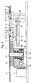
- la figure 4 est une coupe dans le dispositif montré aux figures 1 et 2,
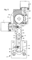
- la figure 5 est une vue de dessus du mécanisme composant l'invention, et
- la figure 6 est un agrandissement de la zone VI montrée en figure 3.
- FIG. 1 is a top view of the device according to the invention where all the parts requiring intervention are installed on a circular carousel,
- FIG. 2 is a view similar to that of FIG. 1, one of the workpieces being installed at a work station,
- FIG. 3 shows the only carousel visible in FIGS. 1 and 2, but removed from the device,
- FIG. 4 is a section through the device shown in FIGS. 1 and 2,
- FIG. 5 is a top view of the mechanism making up the invention, and
- FIG. 6 is an enlargement of zone VI shown in FIG. 3.
Les figures 1 et 2 montrent le dispositif de l'invention dans son idée la
plus générale. On y voit une pluralité d'objets 1 de petites dimensions - ici en
exemple, des montres - susceptibles d'être amenés l'un après l'autre à un
poste de travail 2. De manière bien connue, ce poste de travail comprend
deux accoudoirs 25 et 26 sur lesquels peuvent reposer les avant-bras d'un
opérateur. Entre ces accoudoirs se trouve le poste de travail proprement dit
où l'objet 1' peut subir une intervention (figure 2), par exemple un réglage ou
encore la pose d'au moins un composant, par exemple la glace ou les aiguilles.Figures 1 and 2 show the device of the invention in its idea the
more general. We see a plurality of small objects 1 - here in
for example, watches - which can be brought one after the other to a
Ce dispositif comporte d'abord un carrousel circulaire 3 mû par un
premier organe moteur 5 qu'on aperçoit sur les figures 4 et 5. Le carrousel 5
porte dans sa zone périphérique une pluralité d'éléments porteurs 4 qu'on
voit sur les figures 3, 4 et 5. Ces éléments porteurs 4 portent chacun un
objet 1 auquel doit être assemblé, par exemple, un composant.This device first comprises a
Le dispositif comporte ensuite un chariot 6 mû par un second organe
moteur 7 comme cela est visible sur les figures 4 et 5. Ce chariot est arrangé
pour venir saisir un des éléments porteurs 4 quand cet élément porteur
occupe une position angulaire déterminée propre à amener ledit élément
porteur au poste de travail 2.The device then comprises a
Enfin le dispositif comporte un système de commande symbolisé sur les
figures 1, 2 et 5 par un poussoir 8. Le poussoir 8 peut être actionné par
l'opérateur une fois l'opération d'assemblage terminée. Cet actionnement
ramène via le chariot 6, l'élément porteur 4 sur le carrousel 3, ensuite de quoi
le carrousel tourne jusqu'à ce que l'élément porteur suivant occupe la position
angulaire déterminée propre à l'amener sur le poste de travail 2 via le même
chariot 6.Finally, the device includes a control system symbolized on the
Figures 1, 2 and 5 by a
La description qui vient d'être donnée définit l'invention selon son acception la plus générale. On va examiner maintenant dans le détail un mode de réalisation particulier qui satisfait à ce principe général.The description which has just been given defines the invention according to its most general acceptance. We will now examine in detail a mode of particular realization which satisfies this general principle.
Comme on le voit sur les figures 1 à 3 et particulièrement bien sur la
figure 3, le carrousel 3 comporte dans sa zone périphérique une pluralité de
premières échancrures rectangulaires 13 disposées radialement. Les figures
montrent vingt échancrures 13. Il pourrait y en avoir moins, par exemple
seulement deux, ou plus, par exemple vingt-cinq. Le poste de travail 2 (figures
1, 2 et 5) présente une plaque 14 dans laquelle est pratiquée une seconde
échancrure rectangulaire 15 dont la largeur A est sensiblement égale à la
largeur B des premières échancrures 13. Comme cela est bien visible sur les
figures 3 et 4, l'élément porteur 4 est constitué d'un galet 16 qui présente un
évidement 17 au milieu de sa tranche ce qui lui donne l'aspect d'une rondelle
de yo-yo. L'évidement 17 est engagé soit dans une des premières
échancrures 13 (figures 3 et 4) soit dans la seconde échancrure 17 selon
que, respectivement l'élément porteur 4 se trouve sur le carrousel 3 ou sur le
poste de travail 2. Comme le montre la figure 4, le chariot 6 a pour mission
d'amener l'élément porteur 4, en l'occurrence le galet 16, de la position qu'il
occupe en traits pleins sur le carrousel 3 à la position qu'il occupe en traits
pointillés sur le poste de travail 2. A cet effet, le chariot 6 est pourvu de deux
tenons 18 et 19 entre lesquels s'engage le galet 16 quand la première
échancrure 13 se trouve en face de la seconde échancrure 15. Comme le
montre la figure 4, ces tenons 18 et 19 sont avantageusement recouverts
d'une couche de matériau absorbant les vibrations, par exemple formée d'une
section de tuyau en silicone, enfilée sur ces tenons, afin d'éliminer les vibrations
lors du transport des éléments porteurs 4. Une fois le galet 16 (voir figure 5)
saisi de part et d'autre par les tenons 18 et 19, le chariot 6 avance dans le
sens de la flèche F pour loger ce même galet au fond de la seconde
échancrure 15 comme cela est montré en traits pointillés sur la figure 4. A ce
moment là le chariot 6 occupe la position 6', le galet 16 et son évidement 17
les positions 16' et 17', et les tenons 18 et 19 les positions 18' et 19'.
L'élément porteur 4' est alors en position au poste de travail 2 où peuvent
être exécutés la ou les interventions qu'il y a lieu d'entreprendre sur l'objet 1
(non représenté ici). Au risque de se répéter, on rappellera encore que, pour
que le transport du galet ait lieu, la position angulaire déterminée du carrousel
3 doit être celle pour laquelle une des premières échancrures 13 dudit
carrousel 3 se trouve en prolongement de la seconde échancrure 15 du poste
de travail 2.As seen in Figures 1 to 3 and particularly well on the
Figure 3, the
On a représenté à la figure 3 le carrousel 3 en dehors du contexte de
la machine. On y voit une montre 1 sur laquelle doit être pratiquée une
certaine opération. Cette montre repose sur un élément porteur dont le galet
16 a été dessiné en pointillés. A la droite de ladite montre, a été représenté
un élément porteur 4 avec son galet 16. Dans une première exécution possible
du galet, l'évidement 17 se présente sous la forme d'un cercle 21. Cette
disposition permet de faire tourner l'élément porteur 4 sur lui-même ainsi que
l'objet 1 qui pourrait le surmonter. Ainsi quand l'objet est amené au poste de
travail, l'opérateur a-t-il le loisir de l'amener dans différentes positions
angulaires nécessitées par les interventions à accomplir.Figure 3 shows the
Sur la même figure 3 et à gauche de la montre 1 a été représenté un
élément porteur 4 avec son galet 16. Dans une seconde exécution possible du
galet, l'évidement 17 se présente sous la forme d'un carré 22 rendant
impossible la rotation du galet, le côté du carré étant sensiblement égal à la
largeur B de la première échancrure 13. Quand ce galet parviendra au poste
de travail 2, on comprend qu'il sera empêché de toute rotation puisque la
seconde échancrure 15 possède un largeur B sensiblement égale à la largeur
A de la première échancrure 13. Cette disposition est destinée à des
opérations - par exemple la mise en place des aiguilles de la montre - où il est
impératif que l'objet ne se laisse pas entraíner en rotation.In the same figure 3 and to the left of watch 1, a
Les figures 3 et 6 montrent que la première échancrure 13 est munie
d'un ressort 20 pour maintenir en place l'élément porteur 4. A cet effet, on
pratique un alvéole 30 dans l'échancrure 13, alvéole dans lequel prend place
un ressort fendu de forme tubulaire 20. Quand le galet 16 se trouve au fond
de l'échancrure 13, le ressort 20 fléchit et maintient en place ledit galet. Les
figures 1 et 5 montrent que la seconde échancrure 15 située dans la plaque
14 du poste de travail porte également un alvéole 30 dans lequel prend place
un ressort 20 (non représenté) pour maintenir en place l'élément porteur 4
quand il se trouve au fond de ce second alvéole. Ce maintien en place est
important surtout pour éviter que les objets ne tombent du carrousel 3
quand on transporte ce dernier. Il est important aussi que l'objet en travail
soit bien maintenu en place quand on opère sur lui certaines opérations de
montage et/ou de réglage.Figures 3 and 6 show that the
Si l'on se reporte maintenant à la figure 4, on voit que le carrousel 3
est monté de manière amovible sur un plateau 9 entraíné lui-même par un
premier organe moteur 5. Le carrousel est engagé librement sur l'arbre 31 du
plateau 9. Le plateau 9 est pourvu d'une goupille 10 engagée dans un trou 11
pratiqué dans le carrousel 3. Cette goupille entraíne le carrousel en rotation.
Le premier organe moteur 5 est du type pas à pas capable de faire tourner
le carrousel 3 d'un pas (voir figure 3) correspondant à l'angle α qui sépare
deux éléments porteurs voisins. Cette avance d'un pas s'effectue quand la
pièce en travail 1' (figure 2) a réintégré le carrousel 3 sous l'impulsion du
dispositif de commande 8. Comme le montrent les figures 4 et 5, le premier
organe entraíne une vis sans fin 33 via un accouplement 32. La vis 33 entraíne
à son tour une roue dentée 34 qui est solidaire de l'arbre 31.If we now refer to Figure 4, we see that the
Les explications qui viennent d'être données rendent évident à quel
point l'interchangeabilité du carrousel 3 est aisée. En effet, il suffit de soulever
manuellement le carrousel pour le remplacer par un autre. Ainsi apparaít un
avantage dispensé par l'invention à savoir de disposer de carrousels
facilement manipulables, aisément transportables et même empilables dans
des magasins, avantages que n'offre aucun appareil connu, du moins à la
connaissance du déposant.The explanations just given make it clear to which
point the interchangeability of
Comme on l'a déjà dit plus haut, le dispositif comporte un second
organe moteur 7 pour amener un des éléments porteurs 4 au poste de
travail 2. Ce second organe moteur 7 consiste aussi en un moteur pas à pas.
Comme le montrent les figures 4 et 5, ce second organe moteur 7 entraíne,
par le truchement d'un accouplement 35, une courroie crantée 12 engrenant
avec deux poulies dentées 36 et 37. A cette courroie est attaché le chariot 6
pour véhiculer par un mouvement de va-et-vient, l'élément porteur 4 d'abord
au poste de travail 2, puis au carrousel 3. On a donc ainsi montré un autre
avantage de l'invention qui consiste à sortir un objet à travailler de l'ensemble
des autres objets en attente pour ne pas être gêné par eux.As already mentioned above, the device comprises a
Sans qu'il soit nécessaire de le décrire dans le détail, parce qu'évident de l'homme du métier, le dispositif de l'invention demande à être piloté par un petit ordinateur programmable commandé entre autres par différents senseurs d'état. Outre un clavier de commande avec affichage LCD, ce système de commande permettra par exemple la rotation rapide du carrousel d'un ou de plusieurs pas dans un sens ou dans l'autre, la sélection par le clavier du nombre de positions des disques et la rotation du carrousel sans saisie d'éléments porteurs. Ce système peut comprendre encore un compteur totalisateur et journalier avec remise à zéro et une recherche automatique des références machine à l'enclenchement. En ce qui concerne les senseurs d'état, le dispositif comprendra au moins un détecteur du point zéro du carrousel, un détecteur du point zéro du chariot entraínant l'élément porteur et un détecteur de la présence du carrousel.Without having to describe it in detail, because obvious skilled in the art, the device of the invention requires to be controlled by a small programmable computer controlled among others by different state sensors. In addition to a control keyboard with LCD display, this control system will allow for example the rapid rotation of the carousel of one or more steps in one direction or the other, the selection by the keyboard of the number of positions of the discs and the rotation of the carousel without entering load-bearing elements. This system may also include a total and daily counter with reset and search automatic machine references when switching on. Concerning the state sensors, the device will include at least one zero point detector of the carousel, a zero point detector of the carriage driving the element carrier and a detector of the presence of the carousel.
Le dispositif décrit convient particulièrement bien à traiter des pièces d'horlogerie et, en général, des objets de petites dimensions ayant rapport à la micromécanique.The device described is particularly suitable for treating parts horology and, in general, small objects related to micromechanics.
Claims (8)
Priority Applications (2)
| Application Number | Priority Date | Filing Date | Title |
|---|---|---|---|
| DE69911577T DE69911577D1 (en) | 1999-04-22 | 1999-04-22 | Device for feeding composable objects to a work station |
| EP19990107967 EP1046457B1 (en) | 1999-04-22 | 1999-04-22 | Device for transfer to a work station of items to be assembled |
Applications Claiming Priority (1)
| Application Number | Priority Date | Filing Date | Title |
|---|---|---|---|
| EP19990107967 EP1046457B1 (en) | 1999-04-22 | 1999-04-22 | Device for transfer to a work station of items to be assembled |
Publications (2)
| Publication Number | Publication Date |
|---|---|
| EP1046457A1 true EP1046457A1 (en) | 2000-10-25 |
| EP1046457B1 EP1046457B1 (en) | 2003-09-24 |
Family
ID=8238020
Family Applications (1)
| Application Number | Title | Priority Date | Filing Date |
|---|---|---|---|
| EP19990107967 Expired - Lifetime EP1046457B1 (en) | 1999-04-22 | 1999-04-22 | Device for transfer to a work station of items to be assembled |
Country Status (2)
| Country | Link |
|---|---|
| EP (1) | EP1046457B1 (en) |
| DE (1) | DE69911577D1 (en) |
Families Citing this family (3)
| Publication number | Priority date | Publication date | Assignee | Title |
|---|---|---|---|---|
| DE102007036270B4 (en) * | 2007-07-31 | 2016-11-03 | Bayerische Motoren Werke Aktiengesellschaft | Workpiece storage unit |
| DE102007047795B4 (en) | 2007-11-15 | 2010-04-29 | Fms Montagetechnik Gmbh | Mounting device for mounting assemblies, in particular movements |
| CN109093133A (en) * | 2018-07-26 | 2018-12-28 | 湖州永盛机械铸造有限公司 | A kind of motor casing casting process equipment |
Citations (6)
| Publication number | Priority date | Publication date | Assignee | Title |
|---|---|---|---|---|
| US3290767A (en) * | 1965-06-30 | 1966-12-13 | D Horlogerie Le Coultre Et Cie | Assembly apparatus |
| GB1478946A (en) * | 1975-02-24 | 1977-07-06 | Iva Gebrs Ten Vaarwerk Bv | Assembly tables |
| CH596062A5 (en) * | 1976-01-16 | 1978-02-28 | Lanco Ag | |
| EP0048677A1 (en) * | 1980-08-28 | 1982-03-31 | Société Roland BAILLY Assemblages | Universal working stand of the table-type having exchangeable supporting plates |
| GB2108457A (en) * | 1981-08-29 | 1983-05-18 | Ego Elektro Blanc & Fischer | Assembly stage having a plurality of individual operator positions |
| WO1985001236A1 (en) * | 1983-09-09 | 1985-03-28 | Equipements Industriels De Montage S.A. | Stepping transfer machine for transferring interchangeable work plates |
-
1999
- 1999-04-22 EP EP19990107967 patent/EP1046457B1/en not_active Expired - Lifetime
- 1999-04-22 DE DE69911577T patent/DE69911577D1/en not_active Expired - Lifetime
Patent Citations (6)
| Publication number | Priority date | Publication date | Assignee | Title |
|---|---|---|---|---|
| US3290767A (en) * | 1965-06-30 | 1966-12-13 | D Horlogerie Le Coultre Et Cie | Assembly apparatus |
| GB1478946A (en) * | 1975-02-24 | 1977-07-06 | Iva Gebrs Ten Vaarwerk Bv | Assembly tables |
| CH596062A5 (en) * | 1976-01-16 | 1978-02-28 | Lanco Ag | |
| EP0048677A1 (en) * | 1980-08-28 | 1982-03-31 | Société Roland BAILLY Assemblages | Universal working stand of the table-type having exchangeable supporting plates |
| GB2108457A (en) * | 1981-08-29 | 1983-05-18 | Ego Elektro Blanc & Fischer | Assembly stage having a plurality of individual operator positions |
| WO1985001236A1 (en) * | 1983-09-09 | 1985-03-28 | Equipements Industriels De Montage S.A. | Stepping transfer machine for transferring interchangeable work plates |
Also Published As
| Publication number | Publication date |
|---|---|
| EP1046457B1 (en) | 2003-09-24 |
| DE69911577D1 (en) | 2003-10-30 |
Similar Documents
| Publication | Publication Date | Title |
|---|---|---|
| EP0397558B1 (en) | Machine for applying tubular labels to bottles or similar | |
| WO2008074174A1 (en) | Device for automatically supplying a machining work station of a machine tool with mechanical parts | |
| EP1583617A2 (en) | Product conveying device, in particular fruits or vegetables, adapted to at least weight-based sorting of the products | |
| FR2699100A1 (en) | Machine tool equipped with a disc tool magazine. | |
| EP0768469A1 (en) | Quick acting fastening device, on a threaded driving shaft | |
| EP1046457B1 (en) | Device for transfer to a work station of items to be assembled | |
| FR2897353A1 (en) | PUSH-BUTTON MECHANISM FOR INDIVIDUAL SECTION MACHINE | |
| EP1401746B1 (en) | Device for transporting parts for supplying machines | |
| EP0023269B1 (en) | Printer comprising removable dot print head | |
| EP1231017A1 (en) | High precision transfering device for placing a piece on an immobilized pallet | |
| EP0086166A1 (en) | Pick finding device associated with a dobby or other weaving mechanism | |
| EP0000451B1 (en) | Article-retention clamp, a system for hanging, removing and overlapping application of such a clamp, and a handling device to put this clamp and system into use | |
| FR2539547A1 (en) | REPRODUCING APPARATUS FOR ROTATING RECORDING MEDIA | |
| EP0539308B1 (en) | Publicity board with movable prismatic members | |
| FR2642054A1 (en) | Device for transferring articles from one station to another | |
| FR2559988A1 (en) | COMPONENT ASSEMBLY TABLE DRIVE MECHANISM | |
| FR2492714A1 (en) | ROTARY CAROUSEL MACHINE WITH AXIAL MOVEMENT SERVING MULTIPLE WORKSTATIONS | |
| WO1998001245A1 (en) | Device for adjusting the size of a machine tool blank holder | |
| EP0023268B1 (en) | Dot printer comprising a tiltable print head | |
| FR2657452A1 (en) | HEAD ADJUSTING DEVICE. | |
| FR2798114A1 (en) | Bicycle crank and double chain wheel assembly has slot in larger wheel forming flexible section for shifting chain between chain wheels | |
| EP0114774B1 (en) | Loader and unloader for work pieces with a single driving motor | |
| EP0073687A1 (en) | Automatic tool changing apparatus for machine tools | |
| EP0564360B1 (en) | Offset printing machine | |
| EP0612101A1 (en) | Selection device for bringing an object, for instance a substrate, to a treating station |
Legal Events
| Date | Code | Title | Description |
|---|---|---|---|
| PUAI | Public reference made under article 153(3) epc to a published international application that has entered the european phase |
Free format text: ORIGINAL CODE: 0009012 |
|
| AK | Designated contracting states |
Kind code of ref document: A1 Designated state(s): CH DE FR IT LI |
|
| AX | Request for extension of the european patent |
Free format text: AL;LT;LV;MK;RO;SI |
|
| 17P | Request for examination filed |
Effective date: 20010425 |
|
| AKX | Designation fees paid |
Free format text: CH DE FR IT LI |
|
| 17Q | First examination report despatched |
Effective date: 20020827 |
|
| GRAH | Despatch of communication of intention to grant a patent |
Free format text: ORIGINAL CODE: EPIDOS IGRA |
|
| GRAS | Grant fee paid |
Free format text: ORIGINAL CODE: EPIDOSNIGR3 |
|
| GRAA | (expected) grant |
Free format text: ORIGINAL CODE: 0009210 |
|
| AK | Designated contracting states |
Kind code of ref document: B1 Designated state(s): CH DE FR IT LI |
|
| PG25 | Lapsed in a contracting state [announced via postgrant information from national office to epo] |
Ref country code: IT Free format text: LAPSE BECAUSE OF FAILURE TO SUBMIT A TRANSLATION OF THE DESCRIPTION OR TO PAY THE FEE WITHIN THE PRE;WARNING: LAPSES OF ITALIAN PATENTS WITH EFFECTIVE DATE BEFORE 2007 MAY HAVE OCCURRED AT ANY TIME BEFORE 2007. THE CORRECT EFFECTIVE DATE MAY BE DIFFERENT FROM THE ONE RECORDED.SCRIBED TIME-LIMIT Effective date: 20030924 |
|
| REG | Reference to a national code |
Ref country code: CH Ref legal event code: EP |
|
| REF | Corresponds to: |
Ref document number: 69911577 Country of ref document: DE Date of ref document: 20031030 Kind code of ref document: P |
|
| PG25 | Lapsed in a contracting state [announced via postgrant information from national office to epo] |
Ref country code: DE Free format text: LAPSE BECAUSE OF FAILURE TO SUBMIT A TRANSLATION OF THE DESCRIPTION OR TO PAY THE FEE WITHIN THE PRESCRIBED TIME-LIMIT Effective date: 20031225 |
|
| REG | Reference to a national code |
Ref country code: CH Ref legal event code: NV Representative=s name: ICB INGENIEURS CONSEILS EN BREVETS SA |
|
| PLBE | No opposition filed within time limit |
Free format text: ORIGINAL CODE: 0009261 |
|
| STAA | Information on the status of an ep patent application or granted ep patent |
Free format text: STATUS: NO OPPOSITION FILED WITHIN TIME LIMIT |
|
| 26N | No opposition filed |
Effective date: 20040625 |
|
| PG25 | Lapsed in a contracting state [announced via postgrant information from national office to epo] |
Ref country code: FR Free format text: LAPSE BECAUSE OF NON-PAYMENT OF DUE FEES Effective date: 20041231 |
|
| REG | Reference to a national code |
Ref country code: FR Ref legal event code: ST |
|
| PGFP | Annual fee paid to national office [announced via postgrant information from national office to epo] |
Ref country code: CH Payment date: 20070328 Year of fee payment: 9 |
|
| REG | Reference to a national code |
Ref country code: CH Ref legal event code: PL |
|
| PG25 | Lapsed in a contracting state [announced via postgrant information from national office to epo] |
Ref country code: LI Free format text: LAPSE BECAUSE OF NON-PAYMENT OF DUE FEES Effective date: 20080430 Ref country code: CH Free format text: LAPSE BECAUSE OF NON-PAYMENT OF DUE FEES Effective date: 20080430 |