EP1044832A2 - Mix door driving mechanism for use in automotive air conditioner - Google Patents
Mix door driving mechanism for use in automotive air conditioner Download PDFInfo
- Publication number
- EP1044832A2 EP1044832A2 EP00107297A EP00107297A EP1044832A2 EP 1044832 A2 EP1044832 A2 EP 1044832A2 EP 00107297 A EP00107297 A EP 00107297A EP 00107297 A EP00107297 A EP 00107297A EP 1044832 A2 EP1044832 A2 EP 1044832A2
- Authority
- EP
- European Patent Office
- Prior art keywords
- gear
- driving mechanism
- mix door
- output gear
- air mix
- Prior art date
- Legal status (The legal status is an assumption and is not a legal conclusion. Google has not performed a legal analysis and makes no representation as to the accuracy of the status listed.)
- Granted
Links
Images


Classifications
-
- F—MECHANICAL ENGINEERING; LIGHTING; HEATING; WEAPONS; BLASTING
- F16—ENGINEERING ELEMENTS AND UNITS; GENERAL MEASURES FOR PRODUCING AND MAINTAINING EFFECTIVE FUNCTIONING OF MACHINES OR INSTALLATIONS; THERMAL INSULATION IN GENERAL
- F16H—GEARING
- F16H19/00—Gearings comprising essentially only toothed gears or friction members and not capable of conveying indefinitely-continuing rotary motion
- F16H19/02—Gearings comprising essentially only toothed gears or friction members and not capable of conveying indefinitely-continuing rotary motion for interconverting rotary or oscillating motion and reciprocating motion
- F16H19/04—Gearings comprising essentially only toothed gears or friction members and not capable of conveying indefinitely-continuing rotary motion for interconverting rotary or oscillating motion and reciprocating motion comprising a rack
-
- B—PERFORMING OPERATIONS; TRANSPORTING
- B60—VEHICLES IN GENERAL
- B60H—ARRANGEMENTS OF HEATING, COOLING, VENTILATING OR OTHER AIR-TREATING DEVICES SPECIALLY ADAPTED FOR PASSENGER OR GOODS SPACES OF VEHICLES
- B60H1/00—Heating, cooling or ventilating [HVAC] devices
- B60H1/00642—Control systems or circuits; Control members or indication devices for heating, cooling or ventilating devices
- B60H1/00814—Control systems or circuits characterised by their output, for controlling particular components of the heating, cooling or ventilating installation
- B60H1/00821—Control systems or circuits characterised by their output, for controlling particular components of the heating, cooling or ventilating installation the components being ventilating, air admitting or air distributing devices
- B60H1/00835—Damper doors, e.g. position control
- B60H1/00857—Damper doors, e.g. position control characterised by the means connecting the initiating means, e.g. control lever, to the damper door
-
- F—MECHANICAL ENGINEERING; LIGHTING; HEATING; WEAPONS; BLASTING
- F16—ENGINEERING ELEMENTS AND UNITS; GENERAL MEASURES FOR PRODUCING AND MAINTAINING EFFECTIVE FUNCTIONING OF MACHINES OR INSTALLATIONS; THERMAL INSULATION IN GENERAL
- F16H—GEARING
- F16H19/00—Gearings comprising essentially only toothed gears or friction members and not capable of conveying indefinitely-continuing rotary motion
- F16H19/02—Gearings comprising essentially only toothed gears or friction members and not capable of conveying indefinitely-continuing rotary motion for interconverting rotary or oscillating motion and reciprocating motion
- F16H19/04—Gearings comprising essentially only toothed gears or friction members and not capable of conveying indefinitely-continuing rotary motion for interconverting rotary or oscillating motion and reciprocating motion comprising a rack
- F16H2019/046—Facilitating the engagement or stopping of racks
-
- Y—GENERAL TAGGING OF NEW TECHNOLOGICAL DEVELOPMENTS; GENERAL TAGGING OF CROSS-SECTIONAL TECHNOLOGIES SPANNING OVER SEVERAL SECTIONS OF THE IPC; TECHNICAL SUBJECTS COVERED BY FORMER USPC CROSS-REFERENCE ART COLLECTIONS [XRACs] AND DIGESTS
- Y10—TECHNICAL SUBJECTS COVERED BY FORMER USPC
- Y10T—TECHNICAL SUBJECTS COVERED BY FORMER US CLASSIFICATION
- Y10T74/00—Machine element or mechanism
- Y10T74/18—Mechanical movements
- Y10T74/18568—Reciprocating or oscillating to or from alternating rotary
- Y10T74/188—Reciprocating or oscillating to or from alternating rotary including spur gear
- Y10T74/18808—Reciprocating or oscillating to or from alternating rotary including spur gear with rack
- Y10T74/18816—Curvilinear rack
Definitions
- the present invention relates in general to an automotive air conditioner and more particularly to a driving mechanism for driving a slide type air mix door installed in the air conditioner. More specifically, the present invention relates to the air mix door driving mechanisms of a type that employs a so-called rack-and-pinion arrangement.
- One of the conventional air conditioners is of a type which comprises an intake unit through which outside/inside air is introduced, a cooler unit with an evaporator through which the air is cooled and a heater unit with a heater core through which the air is heated.
- the evaporator is a device set in a refrigerant circulation cooling system, through which a low temperature-low pressure refrigerant from an expansion valve flows for cooling air passing therethrough
- the heater core is a device through which a warmed engine cooling water from an operating engine flows for heating air passing therethrough.
- the air intake unit, the cooler unit and the heater unit are aligned in a case and mounted on a front space of a passenger room of the vehicle.
- the air conditioners of this type tend to have a longer and bulky construction and thus they are not suitable for small-sized motor vehicles.
- air is led to the evaporator to be cooled and then distributed, by means of an air mix door, to upper and/or lower air flow passages, the lower air passage having the heater core installed therein.
- the air mix door is of a slide door type that slides up and down in front of mouth portions of the upper and lower air flow passages. Due to usage of this slide type door, the distance between the evaporator and the heater core can be shortened.
- the cooled air directed to the lower air passage is heated by the heater core and led to an air mix chamber where it is mixed with the cooled air that has passed through the upper air passage.
- the temperature of the air mixed in the air mix chamber depends on the work position of the air mix door.
- the mixed air thus having a certain temperature is then distributed to various portions of a passenger room through various air blowing openings formed in the case.
- mode doors are provided to the air blowing openings for providing the air conditioner with a plurality of air distribution modes.
- a driving mechanism For moving the slide type air mix door in the above-mentioned manner, a driving mechanism is employed which generally comprises two racks which are provided on lateral sides of the air mix door, two gears which are rotatably held by the air conditioner case and meshed with the racks respectively and an electric actuator which drives the gears.
- the electric actuator when the electric actuator is energized for a given time, the gears are rotated by certain angles and thus the air mix door is moved to a desired work position.
- the output shaft of the same inevitably has a dimensional deviation of about ⁇ 2° in operation angle. While, usually the driving mechanism has no means for compensating for such dimensional deviation. Thus, due to such dimensional deviation, it tends to occur that even when the air mix door has come to a terminal stop position, energization of the electric actuator still continues, that is to say, stopping of the electric actuator is not timed with arrival of the air mix door at the stop position. In this case, the electric actuator is attacked by an excessive load inevitably, and thus the life of the electric actuator and thus that of the driving mechanism becomes shortened. In order to solve this drawback, a load sensor that turns off the electric actuator upon sensing the excessive load may be employed. However, in this case, cost performance is sacrificed.
- an object of the present invention is to provide an air mix door driving mechanism for use in an automotive air conditioner, which can protect the electric actuator even when stopping of the electric actuator is not exactly timed with arrival of the air mix door at a stop position.
- the object of the present invention to provide an air mix door driving mechanism for use in an automotive air conditioner, which can assuredly protect the electric actuator even when energization of the electric actuator continues for a while after arrival of the air mix door at the stop position.
- a driving mechanism for driving a slide type air mix door slidably installed in an automotive air conditioner.
- the driving mechanism comprises a rack connected to the air mix door; a gear unit including an input gear, an output gear and a flexible structure through which the input gear and the output gear are integrally and coaxially connected, the output gear being operatively meshed with the rack; and an electric actuator for driving the gear unit through the input gear.
- a gear unit constructed of a plastic.
- the gear unit comprises a hollow input gear; a hollow output gear; and a flexible structure through which the input and output gears are coaxially and integrally connected.
- FIG. 1 there is shown in a sectioned manner an automotive air conditioner to which an air mix door driving mechanism M of the present invention is practically applied.
- the air conditioner comprises a cooler unit 1 and a heater unit 2 which are integrated and installed in a plastic case C.
- these two units 1 and 2 When mounted in an associated motor vehicle, these two units 1 and 2 are aligned and arranged at front and rear positions with respect to a longitudinal axis of the vehicle. Due to after-mentioned unique arrangement of the two units 1 and 2, the case C has a reduced longitudinal length.
- the case C comprises a front-half case and a rear-half case which are coupled in a face-to-face connecting manner.
- an upstream air flow passage UAP there are defined an upstream air flow passage UAP, a heated air flow passage HAP and a bypass air flow passage BAP. That is, the heated air flow passage HAP and the bypass air flow passage BAP are branched from a downstream end of the upstream air flow passage UAP.
- an evaporator 3 which is stood substantially vertically, and within the heated air flow passage HAP, there is installed a heater core 4 which is slightly inclined as shown. Due to presence of the evaporator 3, air flowing in the upstream air flow passage UAP is cooled, and due to presence of the heater core 4, air flowing in the heated air flow passage HAP is heated. Due to the standing posture taken by both the evaporator 3 and heater core 4, the distance therebetween can be reduced and thus the longitudinal length of the case C can be reduced.
- an air mix door D which is slid up and down.
- the air mix door D is of a slide type and driven by the air mix door driving mechanism M as will be described in detail hereinafter.
- the air mix door D By sliding the air mix door D, the open degree of the mouth portion of each air flow passage BAP or HAP is varied. That is, under operation, cooled air from the upstream air flow passage UAP is distributed to the two air flow passages BAP and HAP by a rate determined by the position of the air mix door D.
- the air mix door D assumes its uppermost stop position as shown in Fig. 1, the bypass air flow passage BAP is fully closed and the heated air flow passage HAP is fully opened. In this case, the cooled air from the upstream air flow passage UAP is fully led to the heated air flow passage HAP and thus head.
- bypass air flow passage BAP and the heated air flow passage HAP are mated at their downstream portions to constitute an air mix chamber 9.
- an air guide wall G is provided in the case C, which extends from the heated air flow passage HAP to the air mix chamber 9.
- the air mix door D comprises a door proper 12 which is generally rectangular and curved in shape.
- the door proper 12 has a size to fully close the mouth portion of each of the bypass and heated air flow passages BAP and HAP, and the door proper 12 is so arranged that a concave inner surface thereof faces upstream, that is, toward the evaporator 3.
- This upstream facing arrangement brings about a smoothed air flow toward a desired passage, that is, toward the mouth portion of the bypass air flow passage BAP or that of the heated air flow passage HAP, because as is seen from Fig. 1, the concave inner surface of the door proper 12 functions to smoothly guide the cooled air toward the heated air flow passage HAP (or the bypass air flow passage BAP).
- the door proper 12 comprises upper and lower flat portions 12a and a curved middle portion 12b.
- a convex outer surface of the door proper 12 is lined with a sealing member 15, such as foamed polyurethane mat or the like.
- the door proper 12 is provided at its concave inner surface with two spaced reinforcing plates 16 for obtaining a rigid structure thereof. These reinforcing plates 16 can serve also as air guide plates.
- the door proper 12 has lateral sides which are curved like the curved middle portion 12b. Each lateral side is formed at its concave inner side with a rack 17 which includes a plurality of aligned teeth.
- an air mix door guide mechanism For guiding the upward and downward movement of the mix door D, there is provided an air mix door guide mechanism.
- the guide mechanism comprises two pairs of guide rollers 18 which are rotatably connected to upper and lower corner portions of the lateral sides of the door proper 12. It is to be noted that each guide roller 18 rotates about an axis which is parallel with a common axis of the gear units 20. These two pairs of guide rollers 18 are respectively received in two pairs of guide grooves 19 which are provided in opposed side walls of the case C, as is understood from Figs. 4 and 6.
- each pair of the guide grooves 19 are arranged to constitute an arc of a circle.
- Each guide groove 19 is in the form of a grooved cam. It is to be noted that upper two guide rollers 18 are received in the upper two guide grooves 19 and the lower two guide rollers 18 are in the lower two guide grooves 19.
- the curved air mix door D is thus moved upward and downward along a given way provided by the pair of guide grooves 19 in and along which the corresponding guide rollers 18 travel.
- fixed guide pins may be used in place of the rotatable guide rollers 18.
- the two gear units 20 are employed for moving the curved air mix door D along the given way determined by the two pairs of guide grooves 19, the two gear units 20 are employed. As is seen from Figs. 2 and 4, these two gear units 20 are coaxially connected by a connecting shaft 21.
- an electric actuator 29 is employed, which is mounted to one of the opposed side walls of the casing C.
- the electric actuator 29 comprises an electric motor and a speed reduction gear which are installed in a case.
- each guide groove 19 has a radius of curvature "r" that is substantially equal to that of the curve of the air mix door D.
- the two pairs of guide grooves 19 receive the respective guide rollers 18 of the curved air mix door D. Due to the nature of the four supporting points provided between the air mix door D and the guide grooves 19, stable supporting of the air mix door D relative to the opposed side walls of the case C is achieved and thus even when the air mix door D is attacked by a marked pressure from the flowing air, noisy vibration of the door D is suppressed.
- each guide groove 19 has both ends 19a which are bent obliquely rearward, that is, in a downstream direction. With these bent ends 19a, the air mix door D can be shifted rearward by a certain distance when assuming its uppermost or lowermost stop position, so that as is seen from Figs. 1 and 4, the door D can press the sealing member 15 against partition walls 31 of the case C thereby achieving sealing therebetween. That is, when the air mix door D is brought to such a full close position for the bypass air flow passage BAP or for the heated air flow passage HAP, the closing of the passage BAP or HAP by the air mix door D is assuredly and stably made.
- the sealing member 15 is kept away from the partition walls 31 when the air mix door D assumes intermediate positions other than the uppermost and lowermost stop positions. That is, only when sealing is really needed, the sealing member 15 is pressed against the partition walls 31, which can keep the sealing performance of the sealing member 15 for a longer time. In fact, usually, the sealing member 15 is kept away from the partition walls 31 and thus the movement of air mix door D is carried out smoothly.
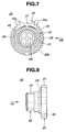
- each gear unit 20 comprises a hollow input gear 22 and a hollow output gear 23 which are coaxially and integrally connected through a hollow cylindrical bearing portion CB (see Fig. 8).
- a cross-shaped hub structure HS within the hollow of the gear unit 20, there is integrally installed a cross-shaped hub structure HS.
- the input gear 22 receives a power from the electric actuator 29 through a transmission member (not shown) and the output gear 23 is meshed with the corresponding rack 17 on the air mix door D.
- Each gear 22 or 23 has teeth 24 or 25 formed thereabout.
- each gear unit 20 is rotatably received in an opening formed in the side wall of the casing C.
- the teeth 25 of the output gear 23 are meshed with the teeth of the corresponding rack 17 of the mix door D.
- the teeth 25 of the output gear 23 comprise a row of shorter teeth 25b which are arranged on a circumferentially major portion of the gear 23 and two groups of taller teeth 25a which are arranged on circumferentially opposed end portions of the gear 23. It is to be noted that the height of the taller teeth 25a gradually increases as the position nears the terminal end.
- the teeth of each rack 17 comprises a row of shorter teeth 17b which are arranged on an intermediate portion of the rack 17 and two groups of taller teeth 17a which are arranged on longitudinally end portions of the rack 17. It is to be noted that the height of the taller teeth 17a gradually increases as the position nears the terminal end.
- the taller teeth 25a of the output gear 23 becomes meshed with the taller teeth 17a of the rack 17. With this, the meshed engagement between the output gear 23 and the rack 17 at the uppermost or lowermost stop position of the air mix door D is assuredly obtained.
- the gear unit 20 is made of a molded plastic provided through injection molding. Polypropylene, polyacetal, Nylon (trade mark) and the like are usable as the material for the gear unit 20.
- the gear unit 20 comprises the hollow input gear 22 and the hollow output gear 23 which are coaxially and integrally connected through the hollow cylindrical bearing portion CB (see Fig. 8).
- the hub structure HS which has a cross-shaped cross section.
- the hub structure HS is constructed to catch one end of the connecting shaft 21 (see Fig. 2).
- the hollow output gear 23 is formed at its cylindrical wall portion with a circularly extending slit 26.
- the slit 26 extends throughout the thickness of the output gear 23.
- a bridge portion 27 of the output gear 23 which has a certain flexibility due to its narrower shape.
- the output gear 23 can have a flexibility relative to the hub structure HS, that is, relative to the input gear 22. More specifically, flection of the output gear 23 is carried out mainly at the flexible bridge portion 27.
- the input gear 22 is applied with a certain driving force from the electric actuator 29, initial rotation of the input gear 22 brings about a certain flection of the output gear 23 at the bridge portion 27.
- the bridge portion 27 is positioned near the taller teeth 25a of the output gear 23, more specifically between the opposed two of the taller teeth 25a. With this arrangement, the bridge portion 27 has a sufficient thickness in radial direction since the portion between the opposed two of the taller teeth 25a is free of the teeth 25. Of course, the bridge portion 27 may be provided at other positions, such as a position near the shorter teeth 25b. Furthermore, as will be described in detail hereinafter, many bridge portions may be provided for the flexible but assured connection between the output gear 23 and the input gear 22.
- the output gear 23 may have two small projections 28 projected into the circularly extending slit 26.
- these projections 28 are formed on an outside surface of the slit 26.
- each projection 28 is brought into abutment with an inside surface of the slit 26 controlling the flexibility of the output gear 23 relative to the input gear 22.
- the projections 28 may be formed on the inside surface of the slit 26.
- the air mix door D fully closes the bypass air flow passage BAP while fully opening the heated air flow passage HAP.
- the upper side guide rollers 18 of the mix door D are received in the upper bent ends 19a of the upper side guide grooves 19, and the lower side guide rollers 18 of the mix door D are received in the upper bent ends 19a of the lower side guide grooves 19.
- the taller teeth 25a at one end part of each output gear 23 engage with the lower-side taller teeth 17a of the corresponding rack 17 of the air mix door D.
- the air mix door D is kept biased rightward in the drawing pressing the sealing member 15 against the partition walls 31. Under this condition, cooled air from the upstream air flow passage UAP enters only the heated air flow passage HAP, as is indicated by a curved thick arrow.
- each gear unit 20 rotates clockwise in Fig. 1. With this, the curved air mix door D is slid downward along the given way provided by the pair of guide grooves 19, as has been described hereinabove.
- the air mix door driving mechanism M assumes the condition as shown in Fig. 9. That is, the upper side guide rollers 18 of the door D are received in the lower bent ends 19a of the upper side guide grooves 19, and the lower side guide rollers 18 of the door D are received in the lower bent ends 19a of the lower side guide grooves 19. Furthermore, the taller teeth 25a at the other end part of the output gear 23 engage with the higher-side taller teeth 17a of the rack 17 of the mix door D. Thus, the air mix door D is biased rightward in Fig. 9 pressing the sealing member 15 against the partition walls 31. Under this condition, cooled air from the upstream air flow passage UAP enters only the bypass air flow passage BAP. That is, in this case, a so-called "full cool mode" is established by the air conditioner.
- stopping of the electric actuator 29 is not exactly timed with arrival of the mix door D at the lowermost stop position, that is to say, if the stopping of the electric actuator 29 takes place a little after the air mix door D arrives at the lowermost stop position, the right side taller teeth 25a of the output gear 23 (as viewed in the drawing) meshed with the upper side taller teeth 17a of the rack 17 are applied with a certain counterforce in the direction of the arrow A.
- the flexibility of the output gear 23 relative to the input gear 22 is easily changed by varying the size and shape of the slit 26, the bridge portion 27 and the projections 28.
- a first modified gear unit 20a which is employable in the mix door driving mechanism of the present invention.
- the circularly extending slit 26a extends around an upper part of the output gear 23 where the right-side and left-side taller teeth 25a of the gear 23 are provided.
- the central angle defined between opposed ends of the slit 26a is about 180° ⁇ 45°, and preferably, about 180° to about 210°.
- a broader bridge portion 27a is defined at a lower part of the output gear 23. In other words, in this first modification 20a, a narrow bridge portion is not provided.
- FIG. 11 there is shown a second modified gear unit 20b which is also employable in the air mix door driving mechanism of the present invention.
- two semi-circular slits 26b are symmetrically provided in the output gear 23 leaving upper and lower narrower bridge portions 27b between mutually facing ends of the slits 26b.
- the upper bridge portion 27b is located near the right side and left side taller teeth 25a and the lower bridge portion 27b is located at a diametrically opposed position of the upper bridge portion 27b.
- the output gear 23 is formed, inside the semi-circular slits 26b, with two shorter arcuate slits 28a and 28b each extending by the upper or lower bridge portion 27b as shown. As shown, the shorter arcuate slits 28a and 28b are located at diametrically opposed portions of the output gear 23.
- each shorter arcuate slit 28a or 28b is smaller than 90°.
- the upper arcuate slit 28a is longer than the lower one 28b.
- two narrower bridge portions 27b are provided.
- the output gear 23 can be flexed relative to the input gear 22 when being applied with a certain counterforce through the taller teeth 25a.
- a third modified gear unit 20c which is also employable in the mix door driving mechanism of the present invention.
- this third modification 20c similar to the above-mentioned second modification 20b, two semi-circular slits 26d are symmetrically provided in the output gear 23 leaving upper and lower narrower bridge portions 27d between mutually facing ends of the slits 26d. Furthermore, similar to the second modification 20b, inside the semi-circular slits 26d, there are provided two arcuate slits 26c each extending by the upper or lower bridge portion 27d as shown. In this third modification 20c, the arcuate slits 26c are sufficiently long to define two narrower bridge portions 27c between mutually facing ends of the arcuate slits 26c. Thus, in this third modification 20c, four narrower bridge portions 27d and 27c are provided.
- the output gear 23 can be flexed relative to the input gear 22 when receiving a certain counterforce through the taller teeth 25a.
Abstract
Description
- The present invention relates in general to an automotive air conditioner and more particularly to a driving mechanism for driving a slide type air mix door installed in the air conditioner. More specifically, the present invention relates to the air mix door driving mechanisms of a type that employs a so-called rack-and-pinion arrangement.
- In order to clarify the task of the present invention, some conventional automotive air conditioners will be briefly described before describing the detail of the present invention.
- One of the conventional air conditioners is of a type which comprises an intake unit through which outside/inside air is introduced, a cooler unit with an evaporator through which the air is cooled and a heater unit with a heater core through which the air is heated. As is known, the evaporator is a device set in a refrigerant circulation cooling system, through which a low temperature-low pressure refrigerant from an expansion valve flows for cooling air passing therethrough, and the heater core is a device through which a warmed engine cooling water from an operating engine flows for heating air passing therethrough. The air intake unit, the cooler unit and the heater unit are aligned in a case and mounted on a front space of a passenger room of the vehicle. However, due to the aligned arrangement of these three units, the air conditioners of this type tend to have a longer and bulky construction and thus they are not suitable for small-sized motor vehicles.
- In view of the above, various compact air conditioners have been proposed and put into practical use for such small-sized motor vehicles. One of the compact type air conditioners has such a construction that the evaporator and the heater core are stood and arranged closely in a case and aligned longitudinally in a motor vehicle. For obtaining much compact construction, a measure has been proposed wherein the cooler and heater units are integrated, by which the evaporator and heater core can be positioned much closer to each other.
- In operation, through the intake unit arranged at one side of the case, air is led to the evaporator to be cooled and then distributed, by means of an air mix door, to upper and/or lower air flow passages, the lower air passage having the heater core installed therein. The air mix door is of a slide door type that slides up and down in front of mouth portions of the upper and lower air flow passages. Due to usage of this slide type door, the distance between the evaporator and the heater core can be shortened. The cooled air directed to the lower air passage is heated by the heater core and led to an air mix chamber where it is mixed with the cooled air that has passed through the upper air passage. Thus, the temperature of the air mixed in the air mix chamber depends on the work position of the air mix door. The mixed air thus having a certain temperature is then distributed to various portions of a passenger room through various air blowing openings formed in the case. Usually, mode doors are provided to the air blowing openings for providing the air conditioner with a plurality of air distribution modes.
- For moving the slide type air mix door in the above-mentioned manner, a driving mechanism is employed which generally comprises two racks which are provided on lateral sides of the air mix door, two gears which are rotatably held by the air conditioner case and meshed with the racks respectively and an electric actuator which drives the gears. Thus, when the electric actuator is energized for a given time, the gears are rotated by certain angles and thus the air mix door is moved to a desired work position.
- However, the above-mentioned driving mechanism has the following drawback.
- That is, due to the nature of the electric actuator, the output shaft of the same inevitably has a dimensional deviation of about ± 2° in operation angle. While, usually the driving mechanism has no means for compensating for such dimensional deviation. Thus, due to such dimensional deviation, it tends to occur that even when the air mix door has come to a terminal stop position, energization of the electric actuator still continues, that is to say, stopping of the electric actuator is not timed with arrival of the air mix door at the stop position. In this case, the electric actuator is attacked by an excessive load inevitably, and thus the life of the electric actuator and thus that of the driving mechanism becomes shortened. In order to solve this drawback, a load sensor that turns off the electric actuator upon sensing the excessive load may be employed. However, in this case, cost performance is sacrificed.
- It is therefore an object of the present invention to provide an air mix door driving mechanism for use in an automotive air conditioner, which is free of the above-mentioned drawback.
- That is, an object of the present invention is to provide an air mix door driving mechanism for use in an automotive air conditioner, which can protect the electric actuator even when stopping of the electric actuator is not exactly timed with arrival of the air mix door at a stop position.
- More specifically, the object of the present invention to provide an air mix door driving mechanism for use in an automotive air conditioner, which can assuredly protect the electric actuator even when energization of the electric actuator continues for a while after arrival of the air mix door at the stop position.
- It is another object of the present invention to provide a gear unit which is suitable for use in the air mix door driving mechanism.
- According to a first aspect of the present invention, there is provided a driving mechanism for driving a slide type air mix door slidably installed in an automotive air conditioner. The driving mechanism comprises a rack connected to the air mix door; a gear unit including an input gear, an output gear and a flexible structure through which the input gear and the output gear are integrally and coaxially connected, the output gear being operatively meshed with the rack; and an electric actuator for driving the gear unit through the input gear.
- According to a second aspect of the present invention, there is provided a gear unit constructed of a plastic. The gear unit comprises a hollow input gear; a hollow output gear; and a flexible structure through which the input and output gears are coaxially and integrally connected.
- Other objects and advantages of the present invention will become apparent from the following description when taken in conjunction with the accompanying drawings, in which:
- Fig. 1 is a sectional view of an automotive air conditioner to which a mix door driving mechanism of the present invention is practically applied;
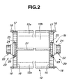
- Fig. 2 is a view taken from the direction of the arrow "II" of Fig. 1, showing the air mix door driving mechanism incorporated with a slide type air mix door;
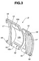
- Fig. 3 is a partially cut perspective view of the slide type air mix door;
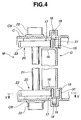
- Fig. 4 is a horizontally sectional view of the air mix door driving mechanism arranged in a casing;
- Fig. 5 is a sectional view taken along the line V-V of Fig. 4;
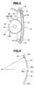
- Fig. 6 is an illustration of paired guide grooves formed in each side wall of the casing;
- Fig. 7 is a side view of a gear unit employed in the air mix door driving mechanism of the invention, which is taken from the direction of the arrow VII of Fig. 8;
- Fig. 8 is a front view of the gear unit, which is taken from the direction of the arrow VIII of Fig. 7;
- Fig. 9 is an illustration showing an advantageous operation of the air mix door driving mechanism of the present invention; and
- Figs. 10, 11 and 12 are views similar to Fig. 7, but showing first, second and third modified gear units employable in the air mix door driving mechanism of the invention.
-
- In the following, the present invention will be described in detail with reference to the accompanying drawings.
- For ease of understanding, the following description will proceed with the aid of several directional terms, such as, upper, lower, left, right, upward, downward and the like. However, it is to be noted that such terms are to be understood with respect to only a drawing or drawings on which corresponding part or parts are shown.
- Referring to Figs. 1 to 9, particularly Fig. 1, there is shown in a sectioned manner an automotive air conditioner to which an air mix door driving mechanism M of the present invention is practically applied.
- As shown, the air conditioner comprises a cooler unit 1 and a heater unit 2 which are integrated and installed in a plastic case C. When mounted in an associated motor vehicle, these two units 1 and 2 are aligned and arranged at front and rear positions with respect to a longitudinal axis of the vehicle. Due to after-mentioned unique arrangement of the two units 1 and 2, the case C has a reduced longitudinal length. The case C comprises a front-half case and a rear-half case which are coupled in a face-to-face connecting manner.
- Within the case C, there are defined an upstream air flow passage UAP, a heated air flow passage HAP and a bypass air flow passage BAP. That is, the heated air flow passage HAP and the bypass air flow passage BAP are branched from a downstream end of the upstream air flow passage UAP.
- Within the upstream air flow passage UAP, there is installed an
evaporator 3 which is stood substantially vertically, and within the heated air flow passage HAP, there is installed aheater core 4 which is slightly inclined as shown. Due to presence of theevaporator 3, air flowing in the upstream air flow passage UAP is cooled, and due to presence of theheater core 4, air flowing in the heated air flow passage HAP is heated. Due to the standing posture taken by both theevaporator 3 andheater core 4, the distance therebetween can be reduced and thus the longitudinal length of the case C can be reduced. - At mouth portions of the bypass air flow passage BAP and heated air flow passage HAP, there is vertically arranged an air mix door D which is slid up and down. The air mix door D is of a slide type and driven by the air mix door driving mechanism M as will be described in detail hereinafter. By sliding the air mix door D, the open degree of the mouth portion of each air flow passage BAP or HAP is varied. That is, under operation, cooled air from the upstream air flow passage UAP is distributed to the two air flow passages BAP and HAP by a rate determined by the position of the air mix door D. When the air mix door D assumes its uppermost stop position as shown in Fig. 1, the bypass air flow passage BAP is fully closed and the heated air flow passage HAP is fully opened. In this case, the cooled air from the upstream air flow passage UAP is fully led to the heated air flow passage HAP and thus head.
- The bypass air flow passage BAP and the heated air flow passage HAP are mated at their downstream portions to constitute an
air mix chamber 9. For this mating, an air guide wall G is provided in the case C, which extends from the heated air flow passage HAP to theair mix chamber 9. Thus, cooled air from the bypass air flow passage SAP and heated air from the heated air flow passage HAP can be mixed in theair mix chamber 9 to have a certain temperature determined by the position of the air mixed door D. - From the
air mix chamber 9, there extend three downstream air flow passages D1, D2 and D3 which lead to respectiveair blow openings pivotal mode doors air mix chamber 9 can be distributed to various portions of a passenger room through selected ones of theair blow openings mode doors opening mode door - As is seen from Fig. 3, the air mix door D comprises a door proper 12 which is generally rectangular and curved in shape. As is seen from Fig. 1, the door proper 12 has a size to fully close the mouth portion of each of the bypass and heated air flow passages BAP and HAP, and the door proper 12 is so arranged that a concave inner surface thereof faces upstream, that is, toward the
evaporator 3. This upstream facing arrangement brings about a smoothed air flow toward a desired passage, that is, toward the mouth portion of the bypass air flow passage BAP or that of the heated air flow passage HAP, because as is seen from Fig. 1, the concave inner surface of the door proper 12 functions to smoothly guide the cooled air toward the heated air flow passage HAP (or the bypass air flow passage BAP). - As is seen from Figs. 2 and 3, the door proper 12 comprises upper and lower
flat portions 12a and a curvedmiddle portion 12b. A convex outer surface of the door proper 12 is lined with a sealingmember 15, such as foamed polyurethane mat or the like. The door proper 12 is provided at its concave inner surface with two spaced reinforcingplates 16 for obtaining a rigid structure thereof. These reinforcingplates 16 can serve also as air guide plates. - As is best shown in Fig. 3, the door proper 12 has lateral sides which are curved like the curved
middle portion 12b. Each lateral side is formed at its concave inner side with arack 17 which includes a plurality of aligned teeth. - As is seen from Figs. 1 and 2, upon assembly,
respective gear units 20 of the air mix door driving mechanism M are operatively engaged with theracks 17 of the door proper 12 in such a manner as will be described hereinafter. Thus, upon operation of the air mix door driving mechanism M, thegear units 20 are rotated and thus the air mix door D is moved upward or downward. - For guiding the upward and downward movement of the mix door D, there is provided an air mix door guide mechanism.
- As is seen from Figs. 2 and 3, the guide mechanism comprises two pairs of
guide rollers 18 which are rotatably connected to upper and lower corner portions of the lateral sides of the door proper 12. It is to be noted that eachguide roller 18 rotates about an axis which is parallel with a common axis of thegear units 20. These two pairs ofguide rollers 18 are respectively received in two pairs ofguide grooves 19 which are provided in opposed side walls of the case C, as is understood from Figs. 4 and 6. - As shown in Fig. 6, each pair of the
guide grooves 19 are arranged to constitute an arc of a circle. Eachguide groove 19 is in the form of a grooved cam. It is to be noted that upper twoguide rollers 18 are received in the upper twoguide grooves 19 and the lower twoguide rollers 18 are in the lower twoguide grooves 19. - The curved air mix door D is thus moved upward and downward along a given way provided by the pair of
guide grooves 19 in and along which thecorresponding guide rollers 18 travel. However, if desired, in place of therotatable guide rollers 18, fixed guide pins may be used. - In the following, detail of the air mix door driving mechanism M will be described.
- As has been described hereinabove, for moving the curved air mix door D along the given way determined by the two pairs of
guide grooves 19, the twogear units 20 are employed. As is seen from Figs. 2 and 4, these twogear units 20 are coaxially connected by a connectingshaft 21. - As is seen from Fig. 1, for driving the
gear units 20, anelectric actuator 29 is employed, which is mounted to one of the opposed side walls of the casing C. Theelectric actuator 29 comprises an electric motor and a speed reduction gear which are installed in a case. - Referring back to Fig. 6, each
guide groove 19 has a radius of curvature "r" that is substantially equal to that of the curve of the air mix door D. As has been mentioned hereinabove, the two pairs ofguide grooves 19 receive therespective guide rollers 18 of the curved air mix door D. Due to the nature of the four supporting points provided between the air mix door D and theguide grooves 19, stable supporting of the air mix door D relative to the opposed side walls of the case C is achieved and thus even when the air mix door D is attacked by a marked pressure from the flowing air, noisy vibration of the door D is suppressed. - As shown in Fig. 6, each
guide groove 19 has bothends 19a which are bent obliquely rearward, that is, in a downstream direction. With thesebent ends 19a, the air mix door D can be shifted rearward by a certain distance when assuming its uppermost or lowermost stop position, so that as is seen from Figs. 1 and 4, the door D can press the sealingmember 15 againstpartition walls 31 of the case C thereby achieving sealing therebetween. That is, when the air mix door D is brought to such a full close position for the bypass air flow passage BAP or for the heated air flow passage HAP, the closing of the passage BAP or HAP by the air mix door D is assuredly and stably made. It is to be noted that the sealingmember 15 is kept away from thepartition walls 31 when the air mix door D assumes intermediate positions other than the uppermost and lowermost stop positions. That is, only when sealing is really needed, the sealingmember 15 is pressed against thepartition walls 31, which can keep the sealing performance of the sealingmember 15 for a longer time. In fact, usually, the sealingmember 15 is kept away from thepartition walls 31 and thus the movement of air mix door D is carried out smoothly. - As is seen from Figs. 2 and 8, each
gear unit 20 comprises ahollow input gear 22 and ahollow output gear 23 which are coaxially and integrally connected through a hollow cylindrical bearing portion CB (see Fig. 8). As will be described in detail hereinafter, within the hollow of thegear unit 20, there is integrally installed a cross-shaped hub structure HS. Theinput gear 22 receives a power from theelectric actuator 29 through a transmission member (not shown) and theoutput gear 23 is meshed with thecorresponding rack 17 on the air mix door D. Eachgear teeth - As is seen from Fig. 4, the hollow cylindrical bearing portion CB of each
gear unit 20 is rotatably received in an opening formed in the side wall of the casing C. - As is seen from Fig. 5, the
teeth 25 of theoutput gear 23 are meshed with the teeth of thecorresponding rack 17 of the mix door D. Thus, when theoutput gear 23 is rotated, the mix door D is slid upward and downward, as has been mentioned hereinabove. Theteeth 25 of theoutput gear 23 comprise a row ofshorter teeth 25b which are arranged on a circumferentially major portion of thegear 23 and two groups oftaller teeth 25a which are arranged on circumferentially opposed end portions of thegear 23. It is to be noted that the height of thetaller teeth 25a gradually increases as the position nears the terminal end. Thus, when theoutput gear 23 is rotated to such a terminal position that one of the two groups oftaller teeth 25a becomes meshed with the teeth of thecorresponding rack 17, the air mix door D is pushed rearward (viz., rightward in the drawing) by thetaller teeth 25a. In the present invention, such terminal position of theoutput gear 23 is given when the air mix door D takes the uppermost or lowermost stop position. - As is also seen from Fig. 5, the teeth of each
rack 17 comprises a row ofshorter teeth 17b which are arranged on an intermediate portion of therack 17 and two groups oftaller teeth 17a which are arranged on longitudinally end portions of therack 17. It is to be noted that the height of thetaller teeth 17a gradually increases as the position nears the terminal end. In the invention, when theoutput gear 23 assumes the above-mentioned terminal position, thetaller teeth 25a of theoutput gear 23 becomes meshed with thetaller teeth 17a of therack 17. With this, the meshed engagement between theoutput gear 23 and therack 17 at the uppermost or lowermost stop position of the air mix door D is assuredly obtained. - Referring to Figs. 7 and 8, there is shown the detail of the
gear unit 20. - The
gear unit 20 is made of a molded plastic provided through injection molding. Polypropylene, polyacetal, Nylon (trade mark) and the like are usable as the material for thegear unit 20. - As has been mentioned hereinabove, the
gear unit 20 comprises thehollow input gear 22 and thehollow output gear 23 which are coaxially and integrally connected through the hollow cylindrical bearing portion CB (see Fig. 8). As is seen from Fig. 7, within the hollow of thegear unit 20, there is coaxially and integrally formed the hub structure HS which has a cross-shaped cross section. The hub structure HS is constructed to catch one end of the connecting shaft 21 (see Fig. 2). - As is seen from Figs. 7 and 8, the
hollow output gear 23 is formed at its cylindrical wall portion with acircularly extending slit 26. As shown in Fig. 8, theslit 26 extends throughout the thickness of theoutput gear 23. As shown in Fig. 7, between opposed ends of thecircularly extending slit 26, there is provided abridge portion 27 of theoutput gear 23 which has a certain flexibility due to its narrower shape. - It is now to be noted that due to provision of the
slit 26 and theflexible bridge portion 27, theoutput gear 23 can have a flexibility relative to the hub structure HS, that is, relative to theinput gear 22. More specifically, flection of theoutput gear 23 is carried out mainly at theflexible bridge portion 27. Thus, when, with the air mix door D kept stopped, theinput gear 22 is applied with a certain driving force from theelectric actuator 29, initial rotation of theinput gear 22 brings about a certain flection of theoutput gear 23 at thebridge portion 27. - As is seen from Fig. 7, the
bridge portion 27 is positioned near thetaller teeth 25a of theoutput gear 23, more specifically between the opposed two of thetaller teeth 25a. With this arrangement, thebridge portion 27 has a sufficient thickness in radial direction since the portion between the opposed two of thetaller teeth 25a is free of theteeth 25. Of course, thebridge portion 27 may be provided at other positions, such as a position near theshorter teeth 25b. Furthermore, as will be described in detail hereinafter, many bridge portions may be provided for the flexible but assured connection between theoutput gear 23 and theinput gear 22. - As is seen from Fig. 7, the
output gear 23 may have twosmall projections 28 projected into thecircularly extending slit 26. In the illustrated embodiment, theseprojections 28 are formed on an outside surface of theslit 26. Upon flection of theoutput gear 23, eachprojection 28 is brought into abutment with an inside surface of theslit 26 controlling the flexibility of theoutput gear 23 relative to theinput gear 22. By changing the size and position of theprojections 28, the flexibility of theoutput gear 23 is varied. Of course, if desired, theprojections 28 may be formed on the inside surface of theslit 26. - In the following, operation of the air mix door driving mechanism M of the present invention will be described with reference to the drawings.
- For ease of understanding, description will be commenced with respect to the condition as shown in Fig. 1.
- In this condition, the air mix door D fully closes the bypass air flow passage BAP while fully opening the heated air flow passage HAP. The upper
side guide rollers 18 of the mix door D are received in the upper bent ends 19a of the upperside guide grooves 19, and the lowerside guide rollers 18 of the mix door D are received in the upper bent ends 19a of the lowerside guide grooves 19. Furthermore, thetaller teeth 25a at one end part of eachoutput gear 23 engage with the lower-sidetaller teeth 17a of thecorresponding rack 17 of the air mix door D. Thus, the air mix door D is kept biased rightward in the drawing pressing the sealingmember 15 against thepartition walls 31. Under this condition, cooled air from the upstream air flow passage UAP enters only the heated air flow passage HAP, as is indicated by a curved thick arrow. - When now the
electric actuator 29 is energized to run in a given direction, eachgear unit 20 rotates clockwise in Fig. 1. With this, the curved air mix door D is slid downward along the given way provided by the pair ofguide grooves 19, as has been described hereinabove. - When the air mix door D comes to the lowermost stop position, a position sensor stops the energization of the
electric actuator 29. At this lowermost stop position of the air mix door D, the bypass air flow passage BAP becomes fully opened and the heated air flow passage HAP becomes fully closed. - In this case, the air mix door driving mechanism M assumes the condition as shown in Fig. 9. That is, the upper
side guide rollers 18 of the door D are received in the lower bent ends 19a of the upperside guide grooves 19, and the lowerside guide rollers 18 of the door D are received in the lower bent ends 19a of the lowerside guide grooves 19. Furthermore, thetaller teeth 25a at the other end part of theoutput gear 23 engage with the higher-sidetaller teeth 17a of therack 17 of the mix door D. Thus, the air mix door D is biased rightward in Fig. 9 pressing the sealingmember 15 against thepartition walls 31. Under this condition, cooled air from the upstream air flow passage UAP enters only the bypass air flow passage BAP. That is, in this case, a so-called "full cool mode" is established by the air conditioner. - In the following, advantageous operation of the air mix door driving mechanism M will be described with reference to Fig. 9.
- If, due to inevitable dimensional deviation of parts of the mechanism M, stopping of the
electric actuator 29 is not exactly timed with arrival of the mix door D at the lowermost stop position, that is to say, if the stopping of theelectric actuator 29 takes place a little after the air mix door D arrives at the lowermost stop position, the right sidetaller teeth 25a of the output gear 23 (as viewed in the drawing) meshed with the upper sidetaller teeth 17a of therack 17 are applied with a certain counterforce in the direction of the arrow A. However, in this case, due to function of theflexible bridge portion 27, the counterforce applied to thetaller teeth 17a brings about a little but certain pivoting of theoutput gear 23 in the direction of the arrow B about thebridge portion 27 until theprojections 28 of theslit 26 are brought into abutment with the inside surface of theslit 26. That is, upon such ill-timed case, theoutput gear 23 effects a return back movement relative to theinput gear 22. This return back phenomenon is quite advantageous because theelectric actuator 29 is prevented from being attacked by an excessive load. That is, such phenomenon can compensate the inevitable dimensional deviation of various parts of the mechanism M and thus smoothly absorb shocks applied to thetaller teeth 25a of theoutput gear 23 and to thetaller teeth 17a of therack 17. - The flexibility of the
output gear 23 relative to theinput gear 22 is easily changed by varying the size and shape of theslit 26, thebridge portion 27 and theprojections 28. - Referring to Fig. 10, there is shown a first modified
gear unit 20a which is employable in the mix door driving mechanism of the present invention. - As shown, in this
modification 20a, thecircularly extending slit 26a extends around an upper part of theoutput gear 23 where the right-side and left-sidetaller teeth 25a of thegear 23 are provided. In this modification, the central angle defined between opposed ends of theslit 26a is about 180° ± 45°, and preferably, about 180° to about 210°. Thus, abroader bridge portion 27a is defined at a lower part of theoutput gear 23. In other words, in thisfirst modification 20a, a narrow bridge portion is not provided. - If, due to ill-timing between the stopping of the
electric actuator 29 and the arrival of the mix door D at the terminal stop position, the right sidetaller teeth 25a of the output gear 23 (as viewed in the drawing) are applied with a certain counterforce like in the above-mentioned manner as shown in Fig. 9, theoutput gear 23 is slightly but certainly flexed in the same direction due to deformation of the upper part of the same. Thus, substantially same advantages are equally obtained in the driving mechanism M employing this first modifiedgear unit 20a. - Referring to Fig. 11, there is shown a second modified
gear unit 20b which is also employable in the air mix door driving mechanism of the present invention. - As shown, in this
second modification 20b, twosemi-circular slits 26b are symmetrically provided in theoutput gear 23 leaving upper and lowernarrower bridge portions 27b between mutually facing ends of theslits 26b. In this modification, theupper bridge portion 27b is located near the right side and left sidetaller teeth 25a and thelower bridge portion 27b is located at a diametrically opposed position of theupper bridge portion 27b. Furthermore, theoutput gear 23 is formed, inside thesemi-circular slits 26b, with two shorterarcuate slits lower bridge portion 27b as shown. As shown, the shorterarcuate slits output gear 23. Preferably, the center angle defined between opposed ends of each shorterarcuate slit arcuate slit 28a is longer than the lower one 28b. Thus, in thissecond modification 20b, twonarrower bridge portions 27b are provided. - For the same reason as mentioned in the above-mentioned
first modification 20a, theoutput gear 23 can be flexed relative to theinput gear 22 when being applied with a certain counterforce through thetaller teeth 25a. - Referring to Fig. 12, there is shown a third modified
gear unit 20c which is also employable in the mix door driving mechanism of the present invention. - As shown, in this
third modification 20c, similar to the above-mentionedsecond modification 20b, twosemi-circular slits 26d are symmetrically provided in theoutput gear 23 leaving upper and lowernarrower bridge portions 27d between mutually facing ends of theslits 26d. Furthermore, similar to thesecond modification 20b, inside thesemi-circular slits 26d, there are provided twoarcuate slits 26c each extending by the upper orlower bridge portion 27d as shown. In thisthird modification 20c, thearcuate slits 26c are sufficiently long to define twonarrower bridge portions 27c between mutually facing ends of thearcuate slits 26c. Thus, in thisthird modification 20c, fournarrower bridge portions - Thus, for the same reason as mentioned hereinabove, the
output gear 23 can be flexed relative to theinput gear 22 when receiving a certain counterforce through thetaller teeth 25a. - The entire contents of Japanese Patent Applications P11-105638 (filed April 13, 1999) and P11-352338 (filed December 10, 1999) are incorporated herein by reference.
- Although the invention has been described above with reference to a certain embodiment of the invention, the invention is not limited to such embodiment. Various modifications and variations of the embodiment will occur to those skilled in the art, in light of the above teachings.
Claims (24)
- A driving mechanism for driving a slide type air mix door slidably installed in an automotive air conditioner, comprising:a rack provided by said air mix door;a gear unit including an input gear, an output gear and a flexible structure through which said input gear and said output gear are integrally and coaxially connected, said output gear being operatively meshed with said rack; andan electric actuator for driving said gear unit through said input gear.
- A driving mechanism as claimed in Claim 1, in which said flexible structure of said gear unit comprises:a hollow extending through the coaxially aligned input and output gears; andat least one circularly extending slit formed in a cylindrical wall portion of said output gear.
- A driving mechanism as claimed in Claim 2, in which said flexible structure of said gear unit further comprises a bridge portion defined between opposed ends of said slit, by which said output gear and said input gear are integrally connected.
- A driving mechanism as claimed in Claim 3, in which said flexible structure of said gear unit further comprises at least one projection projected into said slit from one inner surface of the slit.
- A driving mechanism as claimed in Claim 3, in which said output gear comprises a row of shorter teeth which are arranged on a circumferentially major portion of said output gear and two groups of taller teeth which are arranged on circumferentially opposed ends of said row of shorter teeth.
- A driving mechanism as claimed in Claim 5, in which said rack comprises a row of shorter teeth which are arranged on a major portion of said rack and two groups of taller teeth which are arranged on longitudinally opposed ends of the row of shorter teeth.
- A driving mechanism as claimed in Claim 5, in which said two groups of taller teeth are located in the vicinity of said bridge portion.
- A driving mechanism as claimed in Claim 5, in which said two groups of taller teeth are located at a portion diametrically opposite to said bridge portion.
- A driving mechanism as claimed in Claim 8, in which said two groups of taller teeth are located in the vicinity of a generally middle portion of said slit.
- A driving mechanism as claimed in Claim 2, in which said circularly extending slit comprises:two semi-circular slit sections symmetrically provided;two bridge portions, each being defined between mutually facing ends of the two semi-circular slit sections and integrally connecting said input and output gears; andtwo arcuate slit sections provided inside said semi-circular slit sections at diametrically opposed portions of said output gear.
- A driving mechanism as claimed in Claim 10, in which one of said bridge portions is located in the vicinity of the two groups of taller teeth.
- A driving mechanism as claimed in Claim 11, in which an imaginary line passing through said two bridge portions passes through generally middle portions of said two arcuate slit sections.
- A driving mechanism as claimed in Claim 12, further comprising third and fourth bridge portions, each being defined between mutually facing ends of said two arcuate slit sections.
- A driving mechanism as claimed in Claim 1, in which said rack is a curved rack, and said air mix door is curved, said curved rack being integrally formed on said curved air mix door.
- A driving mechanism as claimed in Claim 14, in which said air mix door is arranged to move along a curved traveling path provided by a mix door guide mechanism.
- A driving mechanism as claimed in Claim 15, in which said air mix door guide mechanism comprises:two pairs of guide grooves, which are provided in opposed side walls of a case of said air conditioner; andtwo pairs of guide rollers rotatably connected to opposed side ends of said air mix door, said guide rollers being operatively engaged with said guide grooves respectively.
- A gear unit constructed of a plastic, comprising:a hollow input gear;a hollow output gear; anda flexible structure through which said input and output gears are coaxially and integrally connected.
- A gear unit as claimed in Claim 17, in which said flexible structure comprises:a hollow extending through the coaxially aligned input and output gears;a circularly extending slit formed around and in a cylindrical wall of said output gear; anda bridge portion defined between opposed ends of said circularly extending slit, by which said output and input gears are integrally connected.
- A gear unit as claimed in Claim 18, further comprising a hub structure which is coaxially and integrally installed in the hollow of said input gear.
- A gear unit as claimed in Claim 19, in which said hub structure has a cross-shaped cross section.
- A gear unit as claimed in Claim 18, in which a plurality of arcuate slits are formed around and in the cylindrical wall of said output gear.
- A gear unit as claimed in Claim 21, in which said arcuate slits are mutually concentrically formed in the cylindrical wall of said output gear.
- A gear unit as claimed in Claim 21, in which a plurality of bridge portions are provided, each being defined between mutually facing ends of paired two of the arcuate slits and integrally connecting said output and input gears.
- A gear unit as claimed in Claim 17, in which said hollow output gear comprises:a row of shorter teeth circumferentially arranged on said cylindrical wall; andtwo groups of taller teeth which are respectively arranged on opposed ends of the row of shorter teeth.
Applications Claiming Priority (4)
| Application Number | Priority Date | Filing Date | Title |
|---|---|---|---|
| JP10563899 | 1999-04-13 | ||
| JP10563899 | 1999-04-13 | ||
| JP35233899 | 1999-12-10 | ||
| JP35233899A JP4166393B2 (en) | 1999-04-13 | 1999-12-10 | Door drive gear for automotive air conditioner |
Publications (3)
| Publication Number | Publication Date |
|---|---|
| EP1044832A2 true EP1044832A2 (en) | 2000-10-18 |
| EP1044832A3 EP1044832A3 (en) | 2002-10-30 |
| EP1044832B1 EP1044832B1 (en) | 2006-03-22 |
Family
ID=26445891
Family Applications (1)
| Application Number | Title | Priority Date | Filing Date |
|---|---|---|---|
| EP00107297A Expired - Lifetime EP1044832B1 (en) | 1999-04-13 | 2000-04-04 | Mix door driving mechanism for use in automotive air conditioner |
Country Status (4)
| Country | Link |
|---|---|
| US (1) | US6354935B1 (en) |
| EP (1) | EP1044832B1 (en) |
| JP (1) | JP4166393B2 (en) |
| DE (1) | DE60026753T2 (en) |
Cited By (4)
| Publication number | Priority date | Publication date | Assignee | Title |
|---|---|---|---|---|
| WO2002063183A2 (en) * | 2001-02-05 | 2002-08-15 | Robert Bosch Gmbh | Actuator with limited travel and emergency uncoupling |
| EP1816016A1 (en) | 2006-02-03 | 2007-08-08 | DENSO THERMAL SYSTEMS S.p.A. | Air distribution assembly for vehicles |
| EP2302261A1 (en) * | 2009-09-25 | 2011-03-30 | Keihin Corporation | Driving force transmission mechanism |
| EP2357100A1 (en) * | 2010-02-17 | 2011-08-17 | Keihin Corporation | Sliding door device |
Families Citing this family (21)
| Publication number | Priority date | Publication date | Assignee | Title |
|---|---|---|---|---|
| US6609563B1 (en) | 1999-04-13 | 2003-08-26 | Calsonic Kansei Corporation | Vehicular air conditioning apparatus including a detachably installed mix door assembly |
| US6802768B2 (en) * | 2002-05-22 | 2004-10-12 | Delphi Technologies, Inc. | Motorized HVAC AC valve |
| JP2005145190A (en) * | 2003-11-13 | 2005-06-09 | Denso Corp | Air conditioner for vehicle |
| US7371161B2 (en) * | 2004-08-27 | 2008-05-13 | Delphi Technologies, Inc. | Sliding film valve driven at edge |
| US7527551B2 (en) | 2004-08-27 | 2009-05-05 | Delphi Technologies, Inc. | Sliding valve, especially for heating, ventilation and air conditioning system |
| JP4962842B2 (en) * | 2006-06-22 | 2012-06-27 | 株式会社ヴァレオジャパン | Sliding door drive device |
| KR101220966B1 (en) | 2006-07-24 | 2013-01-10 | 한라공조주식회사 | Assembling structure of temperature door in an air-conditioner for vehicles |
| JP4832974B2 (en) * | 2006-07-26 | 2011-12-07 | カルソニックカンセイ株式会社 | Sliding door device |
| DE102007015984A1 (en) * | 2007-04-03 | 2008-10-09 | Fischer Automotive Systems Gmbh | Mechanical adjusting device for setting an actuating element |
| JP2009133440A (en) * | 2007-11-30 | 2009-06-18 | Seiko Precision Inc | Gear mechanism and blade drive device |
| JP4957603B2 (en) * | 2008-03-24 | 2012-06-20 | 株式会社デンソー | Air passage opening and closing device |
| JP2009274708A (en) * | 2008-04-15 | 2009-11-26 | Denso Corp | Air passage opening/closing device |
| JP5364479B2 (en) * | 2009-07-14 | 2013-12-11 | 株式会社ケーヒン | Damper device |
| JP5303382B2 (en) * | 2009-07-14 | 2013-10-02 | 株式会社ケーヒン | Damper device |
| KR101220971B1 (en) | 2010-08-30 | 2013-01-11 | 한라공조주식회사 | Air conditioner for vehicle |
| DE102011002606B4 (en) * | 2011-01-13 | 2022-12-15 | Ford Global Technologies, Llc | Ventilation control device for a heating and/or air conditioning system of a vehicle |
| JP5977974B2 (en) * | 2012-03-26 | 2016-08-24 | 株式会社ケーヒン | Vehicle air conditioner and method of assembling the same |
| US9067474B2 (en) * | 2013-03-15 | 2015-06-30 | Denso International America, Inc. | Gear with idle zones |
| DE102015122422B4 (en) * | 2015-12-21 | 2022-01-05 | Hanon Systems | Temperature door drive for two temperature doors in one air conditioning housing |
| KR102512384B1 (en) * | 2018-02-27 | 2023-03-22 | 한온시스템 주식회사 | Air conditioner for vehicle |
| KR102556807B1 (en) * | 2018-10-24 | 2023-07-18 | 한온시스템 주식회사 | Air conditioner for vehicle |
Citations (2)
| Publication number | Priority date | Publication date | Assignee | Title |
|---|---|---|---|---|
| US2976741A (en) * | 1959-03-02 | 1961-03-28 | Louis D Martin | Cluster gear |
| EP0875406A2 (en) * | 1997-04-28 | 1998-11-04 | Mitsubishi Heavy Industries, Ltd. | Air regulator for vehicles |
Family Cites Families (24)
| Publication number | Priority date | Publication date | Assignee | Title |
|---|---|---|---|---|
| US1142051A (en) * | 1910-06-20 | 1915-06-08 | Providence Blower Company | Variable-speed gear. |
| NL260332A (en) * | 1960-01-22 | |||
| US3918313A (en) * | 1974-07-19 | 1975-11-11 | Pitney Bowes Inc | Drive mechanism |
| US4093180A (en) * | 1974-10-08 | 1978-06-06 | James M. Carroll Company | Geared hand wheel for butterfly valves |
| DE3529940C3 (en) | 1985-08-21 | 1999-11-04 | Valeo Klimasysteme Gmbh | Heating and air conditioning device for motor vehicles |
| JPH0618021A (en) | 1992-07-03 | 1994-01-25 | Seiichi Watanabe | Device for combustion |
| JPH0618018A (en) | 1992-07-06 | 1994-01-25 | Matsushita Seiko Co Ltd | Device for disposal of waste |
| US5653144A (en) * | 1993-02-09 | 1997-08-05 | Fenelon; Paul J. | Stress dissipation apparatus |
| US5372065A (en) | 1993-07-02 | 1994-12-13 | Pitney Bowes Inc. | Value selection mechanism including means for weakening a drive gear to permit distortion thereof |
| US5400672A (en) * | 1993-07-09 | 1995-03-28 | Bunch, Jr.; Earnest B. | Gear with inset O-ring for setting backlash |
| JP2970490B2 (en) | 1994-09-22 | 1999-11-02 | 株式会社デンソー | Automotive air conditioners |
| JPH08132852A (en) | 1994-11-10 | 1996-05-28 | Zexel Corp | Air conditioning unit for vehicle |
| JP3596078B2 (en) | 1995-04-11 | 2004-12-02 | 株式会社デンソー | Automotive air conditioners |
| DE19611193B4 (en) | 1995-03-23 | 2006-08-03 | Denso Corp., Kariya | Air conditioning for a motor vehicle |
| JP3646365B2 (en) | 1995-10-03 | 2005-05-11 | 株式会社デンソー | Automotive air conditioner |
| JP3582219B2 (en) | 1996-04-01 | 2004-10-27 | 株式会社デンソー | Automotive air conditioners |
| JP3817332B2 (en) | 1997-04-25 | 2006-09-06 | カルソニックカンセイ株式会社 | Air conditioner for automobile |
| JPH1178482A (en) | 1997-09-12 | 1999-03-23 | Calsonic Corp | Air conditioner mounting structure |
| JP3898298B2 (en) | 1997-09-29 | 2007-03-28 | カルソニックカンセイ株式会社 | Air conditioner for automobile |
| US5924324A (en) * | 1997-10-09 | 1999-07-20 | Ut Automotive Dearborn, Inc. | Movable gear drive windshield wiper |
| JPH11235921A (en) | 1998-02-19 | 1999-08-31 | Zexel:Kk | Air conditioning unit |
| JP3910718B2 (en) | 1998-03-13 | 2007-04-25 | カルソニックカンセイ株式会社 | Air conditioner for automobile |
| US6095007A (en) * | 1999-02-03 | 2000-08-01 | International Business Machines Corporation | Staggered gear for bi-directional operation |
| US6209404B1 (en) * | 1999-10-25 | 2001-04-03 | Trw Inc. | Intermittent geneva actuated mechanism |
-
1999
- 1999-12-10 JP JP35233899A patent/JP4166393B2/en not_active Expired - Fee Related
-
2000
- 2000-04-04 EP EP00107297A patent/EP1044832B1/en not_active Expired - Lifetime
- 2000-04-04 US US09/542,986 patent/US6354935B1/en not_active Expired - Lifetime
- 2000-04-04 DE DE60026753T patent/DE60026753T2/en not_active Expired - Lifetime
Patent Citations (2)
| Publication number | Priority date | Publication date | Assignee | Title |
|---|---|---|---|---|
| US2976741A (en) * | 1959-03-02 | 1961-03-28 | Louis D Martin | Cluster gear |
| EP0875406A2 (en) * | 1997-04-28 | 1998-11-04 | Mitsubishi Heavy Industries, Ltd. | Air regulator for vehicles |
Cited By (10)
| Publication number | Priority date | Publication date | Assignee | Title |
|---|---|---|---|---|
| WO2002063183A2 (en) * | 2001-02-05 | 2002-08-15 | Robert Bosch Gmbh | Actuator with limited travel and emergency uncoupling |
| WO2002063183A3 (en) * | 2001-02-05 | 2002-12-19 | Bosch Gmbh Robert | Actuator with limited travel and emergency uncoupling |
| EP1816016A1 (en) | 2006-02-03 | 2007-08-08 | DENSO THERMAL SYSTEMS S.p.A. | Air distribution assembly for vehicles |
| US7658671B2 (en) | 2006-02-03 | 2010-02-09 | Denso Thermal Systems Spa | Air distribution assembly for vehicles |
| EP2302261A1 (en) * | 2009-09-25 | 2011-03-30 | Keihin Corporation | Driving force transmission mechanism |
| CN102032319A (en) * | 2009-09-25 | 2011-04-27 | 株式会社京浜 | Driving force transmission mechanism |
| CN102032319B (en) * | 2009-09-25 | 2014-01-08 | 株式会社京浜 | Driving force transmission mechanism |
| US9856963B2 (en) | 2009-09-25 | 2018-01-02 | Keihin Corporation | Driving force transmission mechanism |
| EP2357100A1 (en) * | 2010-02-17 | 2011-08-17 | Keihin Corporation | Sliding door device |
| US8939821B2 (en) | 2010-02-17 | 2015-01-27 | Keihin Corporation | Sliding door device |
Also Published As
| Publication number | Publication date |
|---|---|
| JP4166393B2 (en) | 2008-10-15 |
| DE60026753T2 (en) | 2006-09-07 |
| DE60026753D1 (en) | 2006-05-11 |
| EP1044832B1 (en) | 2006-03-22 |
| US6354935B1 (en) | 2002-03-12 |
| JP2000355212A (en) | 2000-12-26 |
| EP1044832A3 (en) | 2002-10-30 |
Similar Documents
| Publication | Publication Date | Title |
|---|---|---|
| US6354935B1 (en) | Mix door driving mechanism for use in automotive air conditioner | |
| US6981690B2 (en) | Air-passage opening/closing device | |
| US6347988B1 (en) | Slide door unit for use in automotive air conditioner | |
| US6450246B1 (en) | Automotive air conditioner | |
| US6609563B1 (en) | Vehicular air conditioning apparatus including a detachably installed mix door assembly | |
| US5701949A (en) | Air conditioner for an automobile | |
| US7779900B2 (en) | Air conditioner for vehicle use | |
| US8480462B2 (en) | Blowing-mode door for vehicle air-conditioning apparatus and vehicle air-conditioning apparatus using the same | |
| EP1078791B1 (en) | Automotive air conditioner | |
| US8113268B2 (en) | Sequential valve member driving mechanism for an HVAC system | |
| US20020084058A1 (en) | Automotive air conditioner | |
| US6913529B2 (en) | Air passage switching device and vehicle air conditioner using the same | |
| US20050227606A1 (en) | Vehicle air conditioning system having air conditioning case | |
| US6101828A (en) | Air conditioning apparatus for vehicle | |
| US6688964B2 (en) | Air passage opening/closing device and vehicle air conditioner using the same | |
| US7694729B2 (en) | Air passage opening/closing device | |
| JPH09175147A (en) | Air conditioner | |
| US6398638B1 (en) | Vehicle air conditioner with manually operated operation member | |
| EP1312494B1 (en) | Automotive air conditioner with flexible plate-like member for controlling flow of air therein | |
| JP4074039B2 (en) | Sliding door device | |
| JP2001171330A (en) | Slide door device | |
| JP3870752B2 (en) | Air passage opening and closing device | |
| KR102531532B1 (en) | Air conditioner for vehicle | |
| JP2001113936A (en) | Slide door device | |
| JP2001113933A (en) | Slide door assembly structure of air conditioner unit for vehicle |
Legal Events
| Date | Code | Title | Description |
|---|---|---|---|
| PUAI | Public reference made under article 153(3) epc to a published international application that has entered the european phase |
Free format text: ORIGINAL CODE: 0009012 |
|
| 17P | Request for examination filed |
Effective date: 20000404 |
|
| AK | Designated contracting states |
Kind code of ref document: A2 Designated state(s): AT BE CH CY DE DK ES FI FR GB GR IE IT LI LU MC NL PT SE |
|
| AX | Request for extension of the european patent |
Free format text: AL;LT;LV;MK;RO;SI |
|
| PUAL | Search report despatched |
Free format text: ORIGINAL CODE: 0009013 |
|
| AK | Designated contracting states |
Kind code of ref document: A3 Designated state(s): AT BE CH CY DE DK ES FI FR GB GR IE IT LI LU MC NL PT SE |
|
| AX | Request for extension of the european patent |
Free format text: AL;LT;LV;MK;RO;SI |
|
| AKX | Designation fees paid |
Designated state(s): DE FR GB |
|
| 17Q | First examination report despatched |
Effective date: 20030624 |
|
| GRAP | Despatch of communication of intention to grant a patent |
Free format text: ORIGINAL CODE: EPIDOSNIGR1 |
|
| GRAS | Grant fee paid |
Free format text: ORIGINAL CODE: EPIDOSNIGR3 |
|
| GRAA | (expected) grant |
Free format text: ORIGINAL CODE: 0009210 |
|
| AK | Designated contracting states |
Kind code of ref document: B1 Designated state(s): DE FR GB |
|
| REG | Reference to a national code |
Ref country code: GB Ref legal event code: FG4D |
|
| REF | Corresponds to: |
Ref document number: 60026753 Country of ref document: DE Date of ref document: 20060511 Kind code of ref document: P |
|
| ET | Fr: translation filed | ||
| PLBE | No opposition filed within time limit |
Free format text: ORIGINAL CODE: 0009261 |
|
| STAA | Information on the status of an ep patent application or granted ep patent |
Free format text: STATUS: NO OPPOSITION FILED WITHIN TIME LIMIT |
|
| 26N | No opposition filed |
Effective date: 20061227 |
|
| REG | Reference to a national code |
Ref country code: FR Ref legal event code: PLFP Year of fee payment: 17 |
|
| REG | Reference to a national code |
Ref country code: FR Ref legal event code: PLFP Year of fee payment: 18 |
|
| PGFP | Annual fee paid to national office [announced via postgrant information from national office to epo] |
Ref country code: FR Payment date: 20170313 Year of fee payment: 18 |
|
| PGFP | Annual fee paid to national office [announced via postgrant information from national office to epo] |
Ref country code: GB Payment date: 20170329 Year of fee payment: 18 |
|
| PGFP | Annual fee paid to national office [announced via postgrant information from national office to epo] |
Ref country code: DE Payment date: 20170329 Year of fee payment: 18 |
|
| REG | Reference to a national code |
Ref country code: DE Ref legal event code: R119 Ref document number: 60026753 Country of ref document: DE |
|
| GBPC | Gb: european patent ceased through non-payment of renewal fee |
Effective date: 20180404 |
|
| PG25 | Lapsed in a contracting state [announced via postgrant information from national office to epo] |
Ref country code: DE Free format text: LAPSE BECAUSE OF NON-PAYMENT OF DUE FEES Effective date: 20181101 |
|
| PG25 | Lapsed in a contracting state [announced via postgrant information from national office to epo] |
Ref country code: GB Free format text: LAPSE BECAUSE OF NON-PAYMENT OF DUE FEES Effective date: 20180404 |
|
| PG25 | Lapsed in a contracting state [announced via postgrant information from national office to epo] |
Ref country code: FR Free format text: LAPSE BECAUSE OF NON-PAYMENT OF DUE FEES Effective date: 20180430 |