EP1044748A2 - Tool clamping mechanism and pull stud - Google Patents
Tool clamping mechanism and pull stud Download PDFInfo
- Publication number
- EP1044748A2 EP1044748A2 EP00301522A EP00301522A EP1044748A2 EP 1044748 A2 EP1044748 A2 EP 1044748A2 EP 00301522 A EP00301522 A EP 00301522A EP 00301522 A EP00301522 A EP 00301522A EP 1044748 A2 EP1044748 A2 EP 1044748A2
- Authority
- EP
- European Patent Office
- Prior art keywords
- sleeve
- pull stud
- tool
- guide hole
- draw bar
- Prior art date
- Legal status (The legal status is an assumption and is not a legal conclusion. Google has not performed a legal analysis and makes no representation as to the accuracy of the status listed.)
- Granted
Links
- 230000007246 mechanism Effects 0.000 title claims description 53
- 230000002093 peripheral effect Effects 0.000 claims description 17
- 239000012530 fluid Substances 0.000 claims description 10
- 238000005096 rolling process Methods 0.000 claims description 8
- 230000000149 penetrating effect Effects 0.000 claims description 6
- 238000004140 cleaning Methods 0.000 abstract description 20
- 239000002173 cutting fluid Substances 0.000 abstract description 10
- 238000001816 cooling Methods 0.000 description 15
- 238000005520 cutting process Methods 0.000 description 6
- 238000000034 method Methods 0.000 description 5
- 230000008569 process Effects 0.000 description 4
- 238000003754 machining Methods 0.000 description 3
- RTZKZFJDLAIYFH-UHFFFAOYSA-N Diethyl ether Chemical compound CCOCC RTZKZFJDLAIYFH-UHFFFAOYSA-N 0.000 description 2
- 230000001133 acceleration Effects 0.000 description 2
- 230000009471 action Effects 0.000 description 2
- 230000000903 blocking effect Effects 0.000 description 2
- 230000008859 change Effects 0.000 description 2
- 230000008878 coupling Effects 0.000 description 2
- 238000010168 coupling process Methods 0.000 description 2
- 238000005859 coupling reaction Methods 0.000 description 2
- 239000010730 cutting oil Substances 0.000 description 2
- 238000011161 development Methods 0.000 description 2
- 238000010586 diagram Methods 0.000 description 2
- 238000012423 maintenance Methods 0.000 description 2
- 238000004891 communication Methods 0.000 description 1
- 238000010276 construction Methods 0.000 description 1
- 230000000994 depressogenic effect Effects 0.000 description 1
- 238000013461 design Methods 0.000 description 1
- 230000000694 effects Effects 0.000 description 1
- 230000002708 enhancing effect Effects 0.000 description 1
- 230000002349 favourable effect Effects 0.000 description 1
- 238000010438 heat treatment Methods 0.000 description 1
- 230000001050 lubricating effect Effects 0.000 description 1
- 239000000463 material Substances 0.000 description 1
- XLYOFNOQVPJJNP-UHFFFAOYSA-N water Substances O XLYOFNOQVPJJNP-UHFFFAOYSA-N 0.000 description 1
Images




Classifications
-
- B—PERFORMING OPERATIONS; TRANSPORTING
- B23—MACHINE TOOLS; METAL-WORKING NOT OTHERWISE PROVIDED FOR
- B23B—TURNING; BORING
- B23B31/00—Chucks; Expansion mandrels; Adaptations thereof for remote control
- B23B31/02—Chucks
- B23B31/24—Chucks characterised by features relating primarily to remote control of the gripping means
- B23B31/26—Chucks characterised by features relating primarily to remote control of the gripping means using mechanical transmission through the working-spindle
- B23B31/261—Chucks characterised by features relating primarily to remote control of the gripping means using mechanical transmission through the working-spindle clamping the end of the toolholder shank
-
- B—PERFORMING OPERATIONS; TRANSPORTING
- B23—MACHINE TOOLS; METAL-WORKING NOT OTHERWISE PROVIDED FOR
- B23B—TURNING; BORING
- B23B31/00—Chucks; Expansion mandrels; Adaptations thereof for remote control
- B23B31/02—Chucks
- B23B31/24—Chucks characterised by features relating primarily to remote control of the gripping means
- B23B31/26—Chucks characterised by features relating primarily to remote control of the gripping means using mechanical transmission through the working-spindle
- B23B31/261—Chucks characterised by features relating primarily to remote control of the gripping means using mechanical transmission through the working-spindle clamping the end of the toolholder shank
- B23B31/263—Chucks characterised by features relating primarily to remote control of the gripping means using mechanical transmission through the working-spindle clamping the end of the toolholder shank by means of balls
-
- B—PERFORMING OPERATIONS; TRANSPORTING
- B23—MACHINE TOOLS; METAL-WORKING NOT OTHERWISE PROVIDED FOR
- B23Q—DETAILS, COMPONENTS, OR ACCESSORIES FOR MACHINE TOOLS, e.g. ARRANGEMENTS FOR COPYING OR CONTROLLING; MACHINE TOOLS IN GENERAL CHARACTERISED BY THE CONSTRUCTION OF PARTICULAR DETAILS OR COMPONENTS; COMBINATIONS OR ASSOCIATIONS OF METAL-WORKING MACHINES, NOT DIRECTED TO A PARTICULAR RESULT
- B23Q1/00—Members which are comprised in the general build-up of a form of machine, particularly relatively large fixed members
- B23Q1/0009—Energy-transferring means or control lines for movable machine parts; Control panels or boxes; Control parts
- B23Q1/0018—Energy-transferring means or control lines for movable machine parts; Control panels or boxes; Control parts comprising hydraulic means
- B23Q1/0027—Energy-transferring means or control lines for movable machine parts; Control panels or boxes; Control parts comprising hydraulic means between moving parts between which an uninterrupted energy-transfer connection is maintained
- B23Q1/0036—Energy-transferring means or control lines for movable machine parts; Control panels or boxes; Control parts comprising hydraulic means between moving parts between which an uninterrupted energy-transfer connection is maintained one of those parts being a tool
-
- B—PERFORMING OPERATIONS; TRANSPORTING
- B23—MACHINE TOOLS; METAL-WORKING NOT OTHERWISE PROVIDED FOR
- B23Q—DETAILS, COMPONENTS, OR ACCESSORIES FOR MACHINE TOOLS, e.g. ARRANGEMENTS FOR COPYING OR CONTROLLING; MACHINE TOOLS IN GENERAL CHARACTERISED BY THE CONSTRUCTION OF PARTICULAR DETAILS OR COMPONENTS; COMBINATIONS OR ASSOCIATIONS OF METAL-WORKING MACHINES, NOT DIRECTED TO A PARTICULAR RESULT
- B23Q11/00—Accessories fitted to machine tools for keeping tools or parts of the machine in good working condition or for cooling work; Safety devices specially combined with or arranged in, or specially adapted for use in connection with, machine tools
- B23Q11/10—Arrangements for cooling or lubricating tools or work
- B23Q11/1015—Arrangements for cooling or lubricating tools or work by supplying a cutting liquid through the spindle
-
- Y—GENERAL TAGGING OF NEW TECHNOLOGICAL DEVELOPMENTS; GENERAL TAGGING OF CROSS-SECTIONAL TECHNOLOGIES SPANNING OVER SEVERAL SECTIONS OF THE IPC; TECHNICAL SUBJECTS COVERED BY FORMER USPC CROSS-REFERENCE ART COLLECTIONS [XRACs] AND DIGESTS
- Y10—TECHNICAL SUBJECTS COVERED BY FORMER USPC
- Y10T—TECHNICAL SUBJECTS COVERED BY FORMER US CLASSIFICATION
- Y10T408/00—Cutting by use of rotating axially moving tool
- Y10T408/94—Tool-support
- Y10T408/95—Tool-support with tool-retaining means
- Y10T408/957—Tool adapter
-
- Y—GENERAL TAGGING OF NEW TECHNOLOGICAL DEVELOPMENTS; GENERAL TAGGING OF CROSS-SECTIONAL TECHNOLOGIES SPANNING OVER SEVERAL SECTIONS OF THE IPC; TECHNICAL SUBJECTS COVERED BY FORMER USPC CROSS-REFERENCE ART COLLECTIONS [XRACs] AND DIGESTS
- Y10—TECHNICAL SUBJECTS COVERED BY FORMER USPC
- Y10T—TECHNICAL SUBJECTS COVERED BY FORMER US CLASSIFICATION
- Y10T409/00—Gear cutting, milling, or planing
- Y10T409/30—Milling
- Y10T409/309352—Cutter spindle or spindle support
- Y10T409/309408—Cutter spindle or spindle support with cutter holder
- Y10T409/309464—Cutter spindle or spindle support with cutter holder and draw bar
Definitions
- the present invention relates to a main spindle structure of a machine tool, and more specifically, to a tool clamping mechanism of the ball-chuck type with high tool retaining stiffness, and a pull stud used for the tool clamping mechanism.
- FIG. 7 is a view showing a main spindle structure that uses a conventional tool clamping mechanism of the ball-chuck type.
- a housing 2 is fixed to the distal end of a spindle head 1, and a main spindle 4 is rotatably held by means of a bearing 3 in the housing 2.
- a draw bar 10 is disposed in a through hole that extends along the axis of the main spindle 4. Balls 7a are embedded in the distal end of the draw bar 10, thus forming a ball chuck portion for holding a pull stud 13 that is attached to a tool shank 5. The pull stud 13 is held by means of the ball chuck portion and pulled into the main spindle 4.
- a spring 11 is provided coaxially surrounding the draw bar 10.
- the draw bar 10 is moved upward as in FIG. 7 by means of the repulsive force of the spring 11, and the pull stud 13 held by means of the ball chuck portion is pulled into the through hole in the main spindle 4.
- a disk spring or coil spring is used as the spring 11.
- the example shown in FIG. 7 is a double coil spring that can generate a clamping force of about 270 kgf. This clamping force is a proper force for the size of the tool shank of the taper-crank type.
- the coil spring compared to the disk spring, is subject to less frictional hysteresis, so that it produces a stable load. Since it smoothly touches the draw bar 10, moreover, the coil spring cannot easily mar the draw bar 10. If it is designed with a stress amplitude not higher than a given value, furthermore, it can repeat the generation of its load substantially permanently, thus enjoying good durability.
- the clamping force is generated by the intimate contact between the taper portions.
- cuttings or other foreign matter must be kept away from the taper surfaces.
- the taper portions can be cleaned by taper cleaning such that foreign matter is discharged to the outside by means of a large quantity of compressed air that is delivered from a center through hole 10c of the draw bar 10 and flows between the taper portions when the taper surface 5a of the tool shank 5 is caused slightly to leave the taper portion of the main spindle 4 by tool changing operation.
- taper cleaning such that foreign matter is discharged to the outside by means of a large quantity of compressed air that is delivered from a center through hole 10c of the draw bar 10 and flows between the taper portions when the taper surface 5a of the tool shank 5 is caused slightly to leave the taper portion of the main spindle 4 by tool changing operation.
- their taper portions are subjected to the taper cleaning with compressed air so that they come intimately into contact with each other.
- a cutting fluid for cooling and lubricating the cutting edge of a tool can be delivered to the tool through the center through hole 10c of the draw bar 10 and a center through hole in the pull stud 13.
- This two-side-restricted tool shank is designed so that both a taper portion and a cylindrical end face of an arbor are brought intimately into contact with a main spindle.
- the tool retaining stiffness of the tool shank of this type can be made higher than that of a tool shank that is designed for intimate contact between taper portions only.
- the two-side-restricted tool shank requires cleaning of the contact portions between the respective end faces of the main spindle and the tool shank. If cuttings and the like adhere to the end contact portions, the tool shank is inevitably inclined when it is attached to the main spindle, so that the machining accuracy is lowered. Accordingly, it is necessary to provide means for supplying plenty of compressed air to the end contact portions to blow off the cuttings and other foreign matter, as well as the taper cleaning.
- center-through cooling has been generalized such that cutting oil is supplied from the center of the main spindle to the tool end.
- it is necessary to seal the tool shank and the clamping mechanism and provide only the tool end with a fluid channel.
- This requirement is not compatible with the requirement of the end face cleaning that involves the necessity to deliver air to the taper portions.
- an expensive clamping mechanism is needed to reconcile the requirements of the center-through cooling and the end face cleaning.
- the adhesion between the respective contact surfaces of the main spindle and the tool shank should be enhanced, in ether case of ad hession between only taper portions or case of restriction by two-side ad hesion between a taper portion and end face.
- the tool pulling force must be increased.
- the tool pulling force of a collet-type clamping mechanism is greater than that of a clamping mechanism of the ball-chuck type.
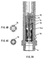
- FIGS. 8A to 8C and FIGS. 9A to 9C show a main spindle structure designed and studied in the process of development of the present invention using the collet-type clamping mechanism.
- the same reference numerals are used for elements and components which are identical with those in the clamping mechanism of the ball-chuck type shown in FIG. 7.
- FIG. 8A shows a state in which the draw bar 10 is withdrawn in the main spindle. In this state, as shown in FIG. 8C, the collet 16 is closed so that it can clamp the pull stud 13.
- the collet 16 is opened so that it can receive pull stud 13.
- a plunger 14, which is incorporated in the draw bar 10, is urged in the upward direction of FIG. 8A by means of a spring 15 in the draw bar 10.
- the draw bar 10 is pushed down, as shown in FIG. 9A, the distal end of the collet 16 opens, as shown in FIG. 8B, so that the passage of the pull stud 13 is allowed.
- the draw bar 10 is caused to ascend by the repulsive force of the spring 11, as shown in FIG. 9B, on the other hand, the distal end of the collet 16 is closed, as shown in FIG. 8C, and then holds and pulls up the pull stud 13.
- compressed air is delivered from a through hole 10a in the center of the draw bar 10 and passes through a through hole 14a in the center of the plunger 14 that is urged upward by means of the spring 15. Then, the compressed air is injected into a space in which the collet 16 and the pull stud 13 are to be coupled to each other, and flows between the taper surface 5a of the tool shank 5 and the taper surface of the main spindle, thereby cleaning the taper surfaces. Further, the compressed air passes through a coupling hole 4a in the main spindle, which connects the distal end face of the spindle and the coupling space for the collet 16 and the pull stud 13. Then, the compressed air is jetted out between the respective end faces of the tool shank 5 and the main spindle to be brought intimately into contact with each other, thereby cleaning these end faces.
- the repulsive force of the spring 15 is set so that the force of the spring 15 to push up the plunger 14 is greater than the force of the compressed air to push down the plunger 14 during the introduction of the compressed air. Therefore, the plunger 14 is kept upwardly open, as shown in FIG. 9A.
- the clamping force (pulling force) has the maximum value that can be attained in the actual space even with use of the double coil spring.
- the spring coil diameter In order to obtain a greater clamping force, it is necessary to increase the spring coil diameter and enlarge the rear part of the shaft of the main spindle. If a rotating part that has nothing to do with the main spindle stiffness is thickened, the inertia increases, and the acceleration performance of the main spindle worsens. In component machining that entails frequent acceleration and deceleration of the main spindle, therefore, the productivity of the machine may be lowered inevitably. To avoid this, it is necessary to restrict the diameter of the clamping mechanism not larger than the existing value.
- the plunger or the like must be provided in the draw bar, as mentioned before, in order to reconcile the center-through cooling and the compressed-air cleaning of the respective contact surfaces of the main spindle and the tool shank. Inevitably, therefore, the resulting structure is complicated and expensive.
- the plunger in the central portion of the collet chuck is brought into contact with the distal end of the pull stud under the pressure from the high-pressure cutting fluid. At the start of discharge of the cutting fluid, therefore, the plunger is caused to run against the distal end of the pull stud by a water hammer impact. Thus, there is a little chance for the plunger to fulfill its function steadily for a long period.
- the collet-type clamping mechanism is not a favorable mechanism for reconciling the center-through cooling and the compressed-air cleaning of the respective contact surfaces of the main spindle and the tool shank.
- An object of the present invention is to provide a compact clamping mechanism of the ball-chuck type enjoying a great clamping force.
- a tool clamping mechanism is a clamping mechanism of the ball-chuck type, in which a draw bar is moved with respect to a main spindle in the axial direction thereof, whereby a ball chuck portion is moved to pull in or release a tool or tool holder.
- the draw bar has, in its outer peripheral portion, a first recess in a shape such that a rolling element can submerge therein.
- the tool clamping mechanism comprises a first sleeve, a second sleeve, and the rolling element.
- the first sleeve is formed having, in its inner peripheral surface, a second recess in a shape such that the rolling element can submerge therein, and is fixed to the inner peripheral surface of the main spindle between the draw bar and the ball chuck portion.
- the second sleeve is located between the first sleeve and the draw bar for movement in the axial direction with respect to the first sleeve and the draw bar.
- the second sleeve is formed having a hole penetrating the main spindle in the radial direction thereof. Further, the rolling element is stored in the through hole of the second sleeve.
- the first recess in the outer peripheral portion of the draw bar and the second recess in the inner peripheral portion of the first sleeve constitute a pulling force amplifying mechanism for amplifying a force along the axial direction of the draw bar, thereby amplifying a pulling force to be transmitted to the ball chuck portion.
- the tool clamping mechanism according to the invention can increase its clamping force by means of the force amplifying mechanism that is attached to the ball chuck portion. Since the size of the main spindle structure is not increased, moreover, the resulting clamping mechanism is compact. Further, the general construction of the clamping mechanism is very simple because the inner periphery of the movable second sleeve and the outer periphery of the pull stud are sealed.
- the pull stud is provided with a guide hole for guiding compressed air
- the respective taper surfaces and end faces of the main spindle and the tool shank to be brought intimately into contact with one another can be cleaned with the compressed air.
- fluid channel switching means is provided in the guide hole of the pull stud, moreover, the fluid channel can be switched between a passage for a cutting fluid for center-through cooling and a passage for compressed air for cleaning, so that the center-through cooling can be reconciled with the cleaning of the respective contact surfaces of the main spindle and the tool shank.
- the clamping mechanism can enjoy simplicity and high reliability.
- the frequency of its use is so low that its durability hardly involves any problem. If the fluid channel switching means in the pull stud gets out of order, moreover, the trouble can be eliminated by only changing the switch means or the whole pull stud.
- FIGS. 1 to 6C A tool clamping mechanism according to one embodiment of the present invention will now be described with reference to the accompanying drawings of FIGS. 1 to 6C.
- the same reference numerals are used for elements and components which are identical with those of the conventional clamping mechanism of the ball-chuck type shown in FIG. 7.
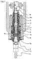
- a main spindle 4 is rotatably supported by means of a bearing 3 in a housing 2 that is attached to a spindle head 1.
- a clamping mechanism for clamping a pull stud 13, a draw bar 10, etc. are arranged in a hole that is formed in the main spindle 4 so as to extend along its axis.
- the clamping mechanism according to the present invention is composed of a first sleeve 9 fixed to the inner peripheral portion of the hole in the main spindle and a second sleeve 8 movable in the axial direction of the main spindle.
- One end of a spring 11 for urging the draw bar 10 upward abuts against the upper end face of the first sleeve 9.
- the draw bar 10 penetrates the spring 11.
- a through hole 10c is formed in the draw bar 10 so as to extend along its axis.
- the first sleeve 9 is provided with a groove 9a that has a slope on its inner peripheral surface.
- the first sleeve 9 is fitted in the hole in the center of the main spindle 4 and fixed to the spindle hole by means of a contracted end portion of the hole and the spring 11.
- the recess or groove 9a that constitutes the slope on the inner peripheral surface of the first sleeve 9 may be given a cubic shape such that it can embrace balls 7b. Since the first sleeve 9 is small-sized, however, the degree of freedom of selection of its material and heat treatment is so high that a standby state can be secured without giving the cubic shape to the groove 9a.
- the groove 9a is shaped by turning only.
- the upper part of the second sleeve 8 which is contracted or reduced in diameter, is inserted in the first sleeve 9.
- the contracted upper end portion of the second sleeve 8 can abut against a spread portion of the draw bar 10.
- a plurality of holes 8a and 8b radially penetrate the lower and upper parts of the second sleeve 8.
- Balls 7a and 7b are embedded in the holes 8a and 8b, respectively.
- the balls 7b that are embedded in the upper holes 8b are adapted to engage the slope of the groove 9a in the first sleeve 9 and slopes of recesses 10d (mentioned later) in the draw bar 10. Further, the balls 7a that are embedded in the lower holes 8a constitute a ball chuck portion for holding the pull stud 13. Although the balls 7a are used as typical examples of rolling elements according to this embodiment, they may be replaced with rollers.
- the recesses 10d are formed in the lower end portion of the draw bar 10, and their respective slopes engage the balls 7b, individually. Further, a spread portion to engage the upper end of the second sleeve 8 is located just above the recesses 10d. The spread portion is provided with a pair of grooves 10a that can engage a lug 8c on the second sleeve 8.
- a slope of each recess 10d of the draw bar 10 can be formed by means of a ball end mill that has a diameter a little greater than that of each ball 7b that engages the slope. Thus, a contact surface pressure that acts on the draw bar 10 is lowered to ensure satisfactory durability.
- a principal function of the clamping mechanism of the invention is to unclamp the tool shank 5 and clamp another tool shank, selected by means of the tool changer, in the main spindle during automatic changing operation.
- This clamping mechanism may be used to hold a pull stud of a tool holder and change the tool holder instead of changing the tool itself.
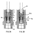
- FIG. 2A shows an initial state in which the draw bar 10 is pressed against the upper end portion by means of the spring 11.
- a roller 12 is advanced or lowered in the automatic tool changing operation, the draw bar 10 that is coupled to a guide ring 10b is pushed down.
- the second sleeve 8 is depressed to take the position shown in FIG. 2B.
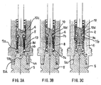
- FIG. 3A shows the tool shank 5 that is inserted into the main spindle 4 by means of the automatic tool changer.
- the pull stud 13 When the pull stud 13 is inserted with its head allowed to pass by the balls 7a, as mentioned before, the balls 7a are spread out by the head of the stud 13.
- the outer peripheral surface of the pull stud 13 and the inner peripheral surface of the second sleeve 8 are sealed by means of an O-ring 8d that is attached to the sleeve 8, and the compressed air delivered from the through hole 10c of the draw bar 10 passes through a channel 13b in the pull stud 13 and flows into the space between a taper surface 5a of the tool shank 5 and a taper surface portion of the main spindle 4, thereby cleaning the two taper surfaces.
- the compressed air passes through a hole 4a that connects an end face of the main spindle 4 and a space just under the junction of the pull stud 13 and the second sleeve 8, thereby cleaning both the respective end faces of the tool shank 5 and the spindle 4.
- FIG. 3C is a view showing a state such that clamping with the main spindle 4 is completed after the draw bar 10 is raised to lift the tool shank 5. The moment the clamping is completed, the supply of the compressed air is stopped, whereupon the tool change is finished. In this state, the balls 7b at the upper part of the draw bar 10 are held in engagement with the respective slopes of the recesses 10d of the draw bar 10 and the slope of the groove 9a in the first sleeve 9.
- the taper surface of the main spindle 4 and the taper surface 5a of the tool shank 5 are brought intimately into contact with each other, and the end face of the spindle 4 and the cylindrical end face of the shank 5 are also brought intimately into contact with each other.
- the tool shank 5 is clamped to the main spindle 4, and high retaining stiffness can be obtained.
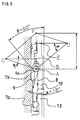
- FIG. 5 is a diagram for illustrating force amplifying action such that pulling forces of the draw bar 10 are transmitted to the second sleeve 8.
- the respective directions and magnitudes of the individual forces are represented by segments.
- ⁇ is the angle of the slopes of the recesses 10d of the draw bar 10
- ⁇ is the angle of the groove 9a of the first sleeve 9.
- a force that each ball 7b receives from the slope of each recess 10d of the draw bar 10 is given as a segment AC in the direction perpendicular to the slope.
- a radial component of force of the segment AC is given by a segment BC.
- a force that each ball 7b receives from the slope of the groove 9a in the first sleeve 9 is given by a segment AD perpendicular to the slope.
- the segment AD represents a force of a magnitude such that its radial component of force ED is equal to the aforesaid radial component of force BC.
- a force that each ball 7b receives from both slopes is given by a segment AF, which represents the sum of the respective axial components of force, AB and AE, of the segments AC and AD.
- the segment AF represents a clamping force with which the pull stud 13 is pulled in.
- the magnitude of this force is given by
- ⁇ (1 + sin ⁇ /(tan ⁇ ⁇ cos ⁇ ))
- FIGS. 6A to 6C are sectional views individually showing various configurations of the pull stud 13 used for the aforesaid clamping mechanism or the like, in which the respective taper surfaces and end faces of the main spindle 4 and the tool shank 5 can be cleaned.
- FIGS. 6A and 6B show a pull stud that is used for center-through cooling
- FIG. 6C shows a pull stud for cleaning only, that is, not for center-through cooling.
- the example shown in FIGS. 2A, 2B, 3A, 3B and 3C is the version shown in FIG. 6C.
- a pull stud 20 for center-through cooling shown in FIGS. 6A and 6B is provided with a first guide hole 20d, which axially penetrates the stud 20 from the distal end of its head, and a second guide hole 20c, which radially extends connecting with the first guide hole 20d and opens sideways in the peripheral surface of the stud 20.
- a plunger 20a a nail-shaped hollow component, is fitted in the first guide hole 20d for advance and retreat, and a spring 20b is disposed so as to urge the plunger 20a upward (or toward the distal end of the head of the pull stud 20).
- the second guide hole 20c is allowed to communicate with the first guide hole 20d without being blocked by the plunger 20a, as shown in FIG.6A.
- the plunger 20a is located at the lower end, resisting the urging force of the spring 20b, on the other hand, the distal end of the plunger 20a and a step portion of the first guide hole 20d come intimately into contact with each other, as shown in FIG.6B, thereby blocking the second guide hole 20c to prevent the communication of the second guide hole 20c with the first guide hole 20d.
- the urging force of the spring 20b is set in the following manner.
- compressed air for cleaning acts on the distal end of the plunger 20a (distal end side of the head of the pull stud 20)
- the plunger 20a is kept from moving by the urging force of the spring 20b.
- a cutting fluid for center-through cooling acts on the distal end of the plunger 20a, its pressure allows the plunger 20a to move to the lower end, resisting the urging force of the spring 20b.
- the plunger 20a can be kept at the upper end by means of the urging force of the spring 20b without moving, as shown in FIG. 6A. Accordingly, the compressed air passes through a through hole in the plunger 20a and the first and second guide holes 20d and 20c. After passing through the second guide hole 20c, the compressed air cleans the respective taper surfaces of the main spindle 4 and the tool shank 5, as described with reference to FIGS. 3A to 3C, and passes through the hole 4a in the main spindle 4 to clean also the respective end faces of the spindle 4 and the shank 5.
- the cutting fluid When the cutting fluid is delivered to the distal end of the head of the pull stud 13, on the other hand, its pressure causes the plunger 20a to move to the lower end, resisting the urging force of the spring 20b, as shown in FIG. 6B. Thereupon, the distal end of the plunger 20a and the step portion of the first guide hole 20d of the pull stud 13 come intimately into contact with each other, thereby blocking the second guide hole 20c. Accordingly, the cutting fluid is guided only to the first guide hole 20d, so that it flows through a hole in the center of a tool and jets out from the distal end of the tool.
- the frequency of use of the plunger 20a as fluid channel switching means located in the pull stud 20 is lower than in the case where the plunger is located in the draw bar, as shown in FIGS. 8A, 9A, 9B and 9C.
- the durability of the plunger is improved. If the plunger 20a is in trouble, moreover, it can be easily replaced with a new one, and besides, the pull stud can be changed entire, so that the maintenance management is easy.
- FIG. 6C shows the pull stud 13 for cleaning without center-through cooling.
- a first guide hole 13a only communicates with a second guide hole 13b without penetrating the pull stud 13.
- the pull stud 13 of this type serves only to clean the respective taper surfaces and end faces of the main spindle 4 and the tool shank 5 to be brought intimately into contact with one another.
- the pull stud is attached to the tool, according to the embodiment described above, it may alternatively be attached to the tool holder, and the tool clamping mechanism of the present invention may be also used for the replacement of the tool holder.
Landscapes
- Engineering & Computer Science (AREA)
- Mechanical Engineering (AREA)
- Gripping On Spindles (AREA)
- Auxiliary Devices For Machine Tools (AREA)
- Jigs For Machine Tools (AREA)
Abstract
Description
Claims (6)
- A tool clamping mechanism of the ball-chuck type, in which a draw bar is moved with respect to a main spindle in the axial direction thereof, whereby a ball chuck portion is moved to pull in or release a tool or tool holder,said draw bar having, in the outer peripheral portion thereof, a first recess in a shape such that a rolling element can submerge therein,said tool clamping mechanism comprising:a first sleeve fixed to the inner peripheral surface of the main spindle between the draw bar and the ball chuck portion, the inner peripheral surface being formed having a second recess in a shape such that the rolling element can submerge therein;a second sleeve located between the first sleeve and the draw bar for movement in the axial direction with respect to the first sleeve and the draw bar, the second sleeve being formed having a hole penetrating the main spindle in the radial direction thereof; andthe rolling element stored in the hole of the second sleeve,the first recess in the outer peripheral portion of the draw bar and the second recess in the inner peripheral portion of the first sleeve constituting a pulling force amplifying mechanism for amplifying a force along the axial direction of the draw bar, thereby amplifying a pulling force to be transmitted to the ball chuck portion.
- The tool clamping mechanism according to claim 1, wherein the inner periphery of said second sleeve and the outer periphery of a pull stud of a tool attached to a tool shank form a sealed structure when the pull stud of the tool held by means of the ball chuck portion is pulled into the main spindle.
- The tool clamping mechanism according to claim 2, wherein said main spindle is provided with a guide hole penetrating the main spindle so as to extend close to the ball chuck portion from the distal end face of the main spindle.
- The pull stud used for the tool clamping mechanism according to claim 3, which is formed having a guide hole extending from the distal end of the head thereof to penetrate the pull stud and opening in the lateral face thereof.
- The pull stud used for the tool clamping mechanism according to claim 3, which is provided with a first guide hole extending from the distal end of the head thereof to penetrate the pull stud axially, a second guide hole connecting with the first guide hole and opening in the lateral face of the pull stud, and fluid channel switching means for opening and closing the second guide hole based on the pressure of a fluid.
- The pull stud used for the tool clamping mechanism according to claim 3, which is formed having a first guide hole axially penetrating the pull stud and a second guide hole connecting with the first guide hole and opening in the lateral face of the pull stud, and which comprises a plunger, having an axially penetrating fluid guide hole and located in the first guide hole for axial movement between a position where the second guide hole is closed and a position where the second guide hole is open, and means for giving the plunger a return force to cause the plunger to move to the position where the second guide hole is open.
Applications Claiming Priority (2)
| Application Number | Priority Date | Filing Date | Title |
|---|---|---|---|
| JP11105140A JP3118512B2 (en) | 1999-04-13 | 1999-04-13 | Tool clamp mechanism and pull stud |
| JP10514099 | 1999-04-13 |
Publications (3)
| Publication Number | Publication Date |
|---|---|
| EP1044748A2 true EP1044748A2 (en) | 2000-10-18 |
| EP1044748A3 EP1044748A3 (en) | 2003-07-23 |
| EP1044748B1 EP1044748B1 (en) | 2005-08-10 |
Family
ID=14399457
Family Applications (1)
| Application Number | Title | Priority Date | Filing Date |
|---|---|---|---|
| EP00301522A Expired - Lifetime EP1044748B1 (en) | 1999-04-13 | 2000-02-25 | Tool clamping mechanism and pull stud |
Country Status (4)
| Country | Link |
|---|---|
| US (1) | US6238152B1 (en) |
| EP (1) | EP1044748B1 (en) |
| JP (1) | JP3118512B2 (en) |
| DE (1) | DE60021792T2 (en) |
Cited By (9)
| Publication number | Priority date | Publication date | Assignee | Title |
|---|---|---|---|---|
| EP1495835A1 (en) * | 2003-07-07 | 2005-01-12 | Fanuc Ltd | Automatic tool changing device for machine tool, with means for cleaning the tool spindle |
| EP1632300A3 (en) * | 2004-09-01 | 2006-06-07 | Fanuc Ltd | Clamping mechanism for tool holder |
| EP1721691A1 (en) * | 2005-05-12 | 2006-11-15 | Antonio Ferraro | Chuck locking device for machine tools |
| EP1704951A3 (en) * | 2005-03-23 | 2008-11-05 | Homag Holzbearbeitungssysteme AG | High speed spindle |
| CN101992308B (en) * | 2009-08-26 | 2012-03-21 | 发得科技工业股份有限公司 | Tool clamping device |
| CN105290853A (en) * | 2015-07-29 | 2016-02-03 | 南通科技投资集团股份有限公司 | Cutter clamping device |
| CN109622999A (en) * | 2019-01-24 | 2019-04-16 | 广州市祈丰机电科技有限公司 | A main shaft pull rod structure |
| CN117583934A (en) * | 2024-01-18 | 2024-02-23 | 泽野精密仪器(昆山)有限公司 | High-precision and high-efficiency machining clamp and machining method for microscope stand |
| TWI919014B (en) | 2022-05-10 | 2026-03-21 | 日商Mck股份有限公司 | Spindle assembly, working machinery equipped with spindle assembly, and balancing testing machine |
Families Citing this family (22)
| Publication number | Priority date | Publication date | Assignee | Title |
|---|---|---|---|---|
| JP3261578B2 (en) * | 1999-07-09 | 2002-03-04 | ホーコス株式会社 | Spindle device of machine tool |
| DE10138330A1 (en) * | 2001-07-27 | 2003-02-13 | Hainbuch Gmbh Spannende Tech | Clamping ring for clamping workpieces has two or more clamping segments connected by elastic spacers with expanding mandrel inserted in undercut section of segments to produce force locking connection |
| JP4798910B2 (en) * | 2001-09-27 | 2011-10-19 | 株式会社テック・ヤスダ | Axial force generator and mechanical chuck cylinder using the same |
| TW566264U (en) * | 2001-11-28 | 2003-12-11 | Ind Tech Res Inst | Tool releasing mechanism used in vertical coupling type spindle of machine tool |
| US7090448B2 (en) * | 2004-08-03 | 2006-08-15 | Ford Motor Company | Tool holder assembly |
| US7588059B2 (en) * | 2005-12-09 | 2009-09-15 | Production Control Units, Inc. | Dispensing tool assembly for evacuating and charging a fluid system |
| JP4890593B2 (en) * | 2009-06-15 | 2012-03-07 | 実 金松 | Grab mechanism such as tool, chuck, clamp mechanism |
| ITTV20120063A1 (en) * | 2012-04-17 | 2013-10-18 | Fcs System S R L | ELECTRO-SPINDLE FOR NUMERICAL CONTROL MACHINES |
| US10160075B2 (en) * | 2013-06-28 | 2018-12-25 | Makino Milling Machine Co., Ltd. | Main spindle device for machine tool and machine tool |
| CN103894858B (en) * | 2014-04-21 | 2016-03-30 | 句容市石狮冲压件厂 | A kind of special-shaped workpiece clamping tooling |
| US10201857B2 (en) * | 2015-08-07 | 2019-02-12 | Kennametal Inc. | Tool holder assemblies and methods of using the same |
| CN106078299B (en) * | 2016-07-13 | 2018-03-27 | 鹰普(中国)有限公司 | A kind of elastic fixture mechanism |
| DE102016013247A1 (en) * | 2016-11-08 | 2018-05-09 | Westinghouse Electric Germany Gmbh | Drilling device for processing pipes on tube sheets in a radioactive environment |
| CN109047888A (en) * | 2017-03-01 | 2018-12-21 | 陈萍 | A kind of battery processing shear of lead pig |
| US11033971B2 (en) | 2017-05-09 | 2021-06-15 | Schaublin Sa | Clamping device for holding a collet |
| CN107186623B (en) * | 2017-07-06 | 2023-04-14 | 南华大学 | Air Rudder Grinding Manual Clamping Fixture |
| CN109175424A (en) * | 2018-10-09 | 2019-01-11 | 杭州泽正机械有限公司 | A kind of aqueous vapor bilateral line structure of chuck |
| CN110293541B (en) * | 2019-06-17 | 2020-11-06 | 上海交通大学 | Via hole cable centering device, snakelike mechanical arm and application method thereof |
| US20230415285A1 (en) * | 2020-11-17 | 2023-12-28 | Fanuc Corporation | Spindle device |
| CN114192819A (en) * | 2020-12-04 | 2022-03-18 | 西华大学 | Multifunctional positioning tool for machining automobile parts with high safety |
| CN113579778A (en) * | 2021-08-23 | 2021-11-02 | 北京德铭纳精密机械有限公司 | Blind rivet tension device with hole blade |
| EP4523823A4 (en) * | 2022-05-10 | 2026-03-11 | Mck co ltd | Spindle device, machine tool with mounted spindle device and balancing machine |
Family Cites Families (13)
| Publication number | Priority date | Publication date | Assignee | Title |
|---|---|---|---|---|
| CH512954A (en) * | 1970-01-16 | 1971-09-30 | Olivetti & Co Spa | Tool clamping device on the spindle of a machine tool |
| US3975984A (en) * | 1975-09-19 | 1976-08-24 | Caterpillar Tractor Co. | Self aligning collect for machine tools |
| US4334811A (en) * | 1979-10-12 | 1982-06-15 | Werkzeugmaschinenfabrik Oerlikon-Buhrle Ag | Spindle extension, especially for drilling and milling machines |
| US4290720A (en) * | 1979-12-17 | 1981-09-22 | R. F. B. Engineering Inc. | Quick self-release and reload tooling device |
| JPS58154033U (en) * | 1982-04-10 | 1983-10-14 | 東芝機械株式会社 | Spindle attachment |
| JPS59142037A (en) * | 1983-02-03 | 1984-08-15 | Toyoda Mach Works Ltd | Tool cramping device for spindle head |
| JPS60114434A (en) * | 1983-11-21 | 1985-06-20 | Mitsui Seiki Kogyo Kk | High frequency motor assembled with tool pull-up system |
| US4692074A (en) * | 1986-04-11 | 1987-09-08 | The Cross Company | Tool coupling arrangement for a tooling assembly |
| DE3936122C1 (en) * | 1989-10-30 | 1990-10-31 | Ott Maschinentechnik Gmbh, 8960 Kempten, De | |
| WO1996009909A1 (en) * | 1994-09-26 | 1996-04-04 | Nikken Kosakusho Works, Ltd. | Tool holder |
| JP3318732B2 (en) * | 1995-09-13 | 2002-08-26 | 株式会社日研工作所 | Spindle parts clamping device |
| JP3785544B2 (en) * | 1996-02-01 | 2006-06-14 | 株式会社ニイガタマシンテクノ | Machine tool spindle equipment |
| JPH1058260A (en) * | 1996-08-19 | 1998-03-03 | Fuji Seiko Kk | Tool holder |
-
1999
- 1999-04-13 JP JP11105140A patent/JP3118512B2/en not_active Expired - Lifetime
-
2000
- 2000-02-25 US US09/513,172 patent/US6238152B1/en not_active Expired - Lifetime
- 2000-02-25 DE DE60021792T patent/DE60021792T2/en not_active Expired - Lifetime
- 2000-02-25 EP EP00301522A patent/EP1044748B1/en not_active Expired - Lifetime
Cited By (12)
| Publication number | Priority date | Publication date | Assignee | Title |
|---|---|---|---|---|
| EP1495835A1 (en) * | 2003-07-07 | 2005-01-12 | Fanuc Ltd | Automatic tool changing device for machine tool, with means for cleaning the tool spindle |
| US7033308B2 (en) | 2003-07-07 | 2006-04-25 | Fanuc Ltd | Automatic tool changing device for machine tool |
| EP1632300A3 (en) * | 2004-09-01 | 2006-06-07 | Fanuc Ltd | Clamping mechanism for tool holder |
| US7418783B2 (en) | 2004-09-01 | 2008-09-02 | Fanuc Ltd | Clamping mechanism for tool holder |
| EP1704951A3 (en) * | 2005-03-23 | 2008-11-05 | Homag Holzbearbeitungssysteme AG | High speed spindle |
| EP1721691A1 (en) * | 2005-05-12 | 2006-11-15 | Antonio Ferraro | Chuck locking device for machine tools |
| CN101992308B (en) * | 2009-08-26 | 2012-03-21 | 发得科技工业股份有限公司 | Tool clamping device |
| CN105290853A (en) * | 2015-07-29 | 2016-02-03 | 南通科技投资集团股份有限公司 | Cutter clamping device |
| CN109622999A (en) * | 2019-01-24 | 2019-04-16 | 广州市祈丰机电科技有限公司 | A main shaft pull rod structure |
| TWI919014B (en) | 2022-05-10 | 2026-03-21 | 日商Mck股份有限公司 | Spindle assembly, working machinery equipped with spindle assembly, and balancing testing machine |
| CN117583934A (en) * | 2024-01-18 | 2024-02-23 | 泽野精密仪器(昆山)有限公司 | High-precision and high-efficiency machining clamp and machining method for microscope stand |
| CN117583934B (en) * | 2024-01-18 | 2024-04-02 | 泽野精密仪器(昆山)有限公司 | High-precision and high-efficiency machining clamp and machining method for microscope stand |
Also Published As
| Publication number | Publication date |
|---|---|
| US6238152B1 (en) | 2001-05-29 |
| DE60021792D1 (en) | 2005-09-15 |
| DE60021792T2 (en) | 2006-02-16 |
| EP1044748A3 (en) | 2003-07-23 |
| JP3118512B2 (en) | 2000-12-18 |
| EP1044748B1 (en) | 2005-08-10 |
| JP2000296404A (en) | 2000-10-24 |
Similar Documents
| Publication | Publication Date | Title |
|---|---|---|
| EP1044748B1 (en) | Tool clamping mechanism and pull stud | |
| US5690137A (en) | Spindle device | |
| EP1726399B1 (en) | Clamp device | |
| JP4086281B2 (en) | Clamping device | |
| EP2000238B1 (en) | Spindle head device and machine tool | |
| EP1203631B2 (en) | Spindle device of machine tool | |
| EP1316386B1 (en) | Spindle device of machine tool | |
| US5676506A (en) | Spindle device for machine tools | |
| US5437465A (en) | Tool changing device on a hand-operated machine tool | |
| EP1561539B1 (en) | Tool holder of machine tool | |
| US20030170087A1 (en) | Spindle device of machine tool | |
| JPH10277862A (en) | Tool holder and tool holding device of metalcutting machine tool | |
| US5150994A (en) | Spindle means of machine center | |
| JP4730939B2 (en) | Spindle device | |
| KR100758884B1 (en) | Tool for machining and deburring workpieces and method therefor | |
| US7244080B2 (en) | Quick-change insert for tools, especially for thread drills | |
| JP4782312B2 (en) | Tool holder mounting device | |
| JP3479760B2 (en) | Spindle device of machine tool | |
| JP3453674B2 (en) | Spindle device of machine tool | |
| JP2020066114A (en) | Chuck unit | |
| JP2005186254A (en) | Tool holder and method for supplying mist to tool | |
| JPH0544406U (en) | Machine tool spindle structure | |
| JPS6034244A (en) | Air supply device | |
| SU984722A1 (en) | Rechangeable chuck | |
| KR100552415B1 (en) | Workpiece Support |
Legal Events
| Date | Code | Title | Description |
|---|---|---|---|
| PUAI | Public reference made under article 153(3) epc to a published international application that has entered the european phase |
Free format text: ORIGINAL CODE: 0009012 |
|
| AK | Designated contracting states |
Kind code of ref document: A2 Designated state(s): AT BE CH CY DE DK ES FI FR GB GR IE IT LI LU MC NL PT SE |
|
| AX | Request for extension of the european patent |
Free format text: AL;LT;LV;MK;RO;SI |
|
| RIC1 | Information provided on ipc code assigned before grant |
Ipc: 7B 23Q 11/10 B Ipc: 7B 23Q 1/00 B Ipc: 7B 23B 31/26 A |
|
| PUAL | Search report despatched |
Free format text: ORIGINAL CODE: 0009013 |
|
| AK | Designated contracting states |
Designated state(s): AT BE CH CY DE DK ES FI FR GB GR IE IT LI LU MC NL PT SE |
|
| AX | Request for extension of the european patent |
Extension state: AL LT LV MK RO SI |
|
| 17P | Request for examination filed |
Effective date: 20030708 |
|
| AKX | Designation fees paid |
Designated state(s): DE |
|
| RAP1 | Party data changed (applicant data changed or rights of an application transferred) |
Owner name: FANUC LTD |
|
| 17Q | First examination report despatched |
Effective date: 20040927 |
|
| GRAP | Despatch of communication of intention to grant a patent |
Free format text: ORIGINAL CODE: EPIDOSNIGR1 |
|
| GRAS | Grant fee paid |
Free format text: ORIGINAL CODE: EPIDOSNIGR3 |
|
| GRAA | (expected) grant |
Free format text: ORIGINAL CODE: 0009210 |
|
| AK | Designated contracting states |
Kind code of ref document: B1 Designated state(s): DE |
|
| REF | Corresponds to: |
Ref document number: 60021792 Country of ref document: DE Date of ref document: 20050915 Kind code of ref document: P |
|
| PLBE | No opposition filed within time limit |
Free format text: ORIGINAL CODE: 0009261 |
|
| STAA | Information on the status of an ep patent application or granted ep patent |
Free format text: STATUS: NO OPPOSITION FILED WITHIN TIME LIMIT |
|
| 26N | No opposition filed |
Effective date: 20060511 |
|
| REG | Reference to a national code |
Ref country code: DE Ref legal event code: R082 Ref document number: 60021792 Country of ref document: DE Representative=s name: HASELTINE LAKE LLP, DE |
|
| PGFP | Annual fee paid to national office [announced via postgrant information from national office to epo] |
Ref country code: DE Payment date: 20190212 Year of fee payment: 20 |
|
| REG | Reference to a national code |
Ref country code: DE Ref legal event code: R071 Ref document number: 60021792 Country of ref document: DE |