EP2000238B1 - Spindle head device and machine tool - Google Patents
Spindle head device and machine tool Download PDFInfo
- Publication number
- EP2000238B1 EP2000238B1 EP07741051.2A EP07741051A EP2000238B1 EP 2000238 B1 EP2000238 B1 EP 2000238B1 EP 07741051 A EP07741051 A EP 07741051A EP 2000238 B1 EP2000238 B1 EP 2000238B1
- Authority
- EP
- European Patent Office
- Prior art keywords
- tool
- spindle
- support member
- hole
- head device
- Prior art date
- Legal status (The legal status is an assumption and is not a legal conclusion. Google has not performed a legal analysis and makes no representation as to the accuracy of the status listed.)
- Ceased
Links
- 230000007246 mechanism Effects 0.000 claims description 80
- 238000006073 displacement reaction Methods 0.000 claims description 35
- 239000012530 fluid Substances 0.000 claims description 23
- 230000000149 penetrating effect Effects 0.000 claims description 8
- 238000004140 cleaning Methods 0.000 claims description 5
- 239000012809 cooling fluid Substances 0.000 claims description 5
- 230000004323 axial length Effects 0.000 claims description 3
- 230000000717 retained effect Effects 0.000 description 20
- 210000000078 claw Anatomy 0.000 description 14
- 238000012423 maintenance Methods 0.000 description 14
- 241000549194 Euonymus europaeus Species 0.000 description 12
- 230000004048 modification Effects 0.000 description 5
- 238000012986 modification Methods 0.000 description 5
- 238000003754 machining Methods 0.000 description 4
- 230000008901 benefit Effects 0.000 description 3
- 238000003825 pressing Methods 0.000 description 3
- 230000008878 coupling Effects 0.000 description 2
- 238000010168 coupling process Methods 0.000 description 2
- 238000005859 coupling reaction Methods 0.000 description 2
- 238000004519 manufacturing process Methods 0.000 description 2
- 238000003801 milling Methods 0.000 description 2
- 239000011435 rock Substances 0.000 description 2
- 230000009471 action Effects 0.000 description 1
- 238000005452 bending Methods 0.000 description 1
- 238000005520 cutting process Methods 0.000 description 1
- 230000000694 effects Effects 0.000 description 1
- 238000000034 method Methods 0.000 description 1
- 230000008569 process Effects 0.000 description 1
- 230000004044 response Effects 0.000 description 1
Images


Classifications
-
- B—PERFORMING OPERATIONS; TRANSPORTING
- B23—MACHINE TOOLS; METAL-WORKING NOT OTHERWISE PROVIDED FOR
- B23B—TURNING; BORING
- B23B31/00—Chucks; Expansion mandrels; Adaptations thereof for remote control
- B23B31/02—Chucks
- B23B31/24—Chucks characterised by features relating primarily to remote control of the gripping means
- B23B31/26—Chucks characterised by features relating primarily to remote control of the gripping means using mechanical transmission through the working-spindle
- B23B31/261—Chucks characterised by features relating primarily to remote control of the gripping means using mechanical transmission through the working-spindle clamping the end of the toolholder shank
- B23B31/265—Chucks characterised by features relating primarily to remote control of the gripping means using mechanical transmission through the working-spindle clamping the end of the toolholder shank by means of collets
-
- B—PERFORMING OPERATIONS; TRANSPORTING
- B23—MACHINE TOOLS; METAL-WORKING NOT OTHERWISE PROVIDED FOR
- B23B—TURNING; BORING
- B23B31/00—Chucks; Expansion mandrels; Adaptations thereof for remote control
- B23B31/02—Chucks
- B23B31/10—Chucks characterised by the retaining or gripping devices or their immediate operating means
- B23B31/117—Retention by friction only, e.g. using springs, resilient sleeves, tapers
-
- B—PERFORMING OPERATIONS; TRANSPORTING
- B23—MACHINE TOOLS; METAL-WORKING NOT OTHERWISE PROVIDED FOR
- B23Q—DETAILS, COMPONENTS, OR ACCESSORIES FOR MACHINE TOOLS, e.g. ARRANGEMENTS FOR COPYING OR CONTROLLING; MACHINE TOOLS IN GENERAL CHARACTERISED BY THE CONSTRUCTION OF PARTICULAR DETAILS OR COMPONENTS; COMBINATIONS OR ASSOCIATIONS OF METAL-WORKING MACHINES, NOT DIRECTED TO A PARTICULAR RESULT
- B23Q11/00—Accessories fitted to machine tools for keeping tools or parts of the machine in good working condition or for cooling work; Safety devices specially combined with or arranged in, or specially adapted for use in connection with, machine tools
- B23Q11/10—Arrangements for cooling or lubricating tools or work
-
- B—PERFORMING OPERATIONS; TRANSPORTING
- B23—MACHINE TOOLS; METAL-WORKING NOT OTHERWISE PROVIDED FOR
- B23B—TURNING; BORING
- B23B2260/00—Details of constructional elements
- B23B2260/034—Drawbars
-
- Y—GENERAL TAGGING OF NEW TECHNOLOGICAL DEVELOPMENTS; GENERAL TAGGING OF CROSS-SECTIONAL TECHNOLOGIES SPANNING OVER SEVERAL SECTIONS OF THE IPC; TECHNICAL SUBJECTS COVERED BY FORMER USPC CROSS-REFERENCE ART COLLECTIONS [XRACs] AND DIGESTS
- Y10—TECHNICAL SUBJECTS COVERED BY FORMER USPC
- Y10T—TECHNICAL SUBJECTS COVERED BY FORMER US CLASSIFICATION
- Y10T409/00—Gear cutting, milling, or planing
- Y10T409/30—Milling
- Y10T409/303976—Milling with means to control temperature or lubricate
- Y10T409/304032—Cutter or work
-
- Y—GENERAL TAGGING OF NEW TECHNOLOGICAL DEVELOPMENTS; GENERAL TAGGING OF CROSS-SECTIONAL TECHNOLOGIES SPANNING OVER SEVERAL SECTIONS OF THE IPC; TECHNICAL SUBJECTS COVERED BY FORMER USPC CROSS-REFERENCE ART COLLECTIONS [XRACs] AND DIGESTS
- Y10—TECHNICAL SUBJECTS COVERED BY FORMER USPC
- Y10T—TECHNICAL SUBJECTS COVERED BY FORMER US CLASSIFICATION
- Y10T409/00—Gear cutting, milling, or planing
- Y10T409/30—Milling
- Y10T409/309352—Cutter spindle or spindle support
- Y10T409/309408—Cutter spindle or spindle support with cutter holder
- Y10T409/309464—Cutter spindle or spindle support with cutter holder and draw bar
Definitions
- the present invention relates to a spindle head device installed in a machine tool and including a tool spindle.
- the present invention also relates to a machine tool equipped with a spindle head device including a tool spindle.
- a machine tool e.g., a milling machine, a machining center, etc.
- a spindle a so-called tool spindle
- various cutting operations can be carried out by selecting a suitable tool from among several types of tools respectively fitted to tool holders and attaching it to an axial end of the spindle (hereinafter referred to as a spindle nose) in an exchangeable manner.
- a machine tool is provided, inside a spindle head device including a tool spindle, with a tool retaining mechanism for detachably retaining respective tool holders on the spindle nose.
- a tool holder is provided with a chuck for chucking a tool, a shank adapted to be received and held in the spindle nose, and a flange adapted to be grasped by an automatic tool changer (ATC) and usually provided between the chuck and the shank.
- the spindle nose is provided with a receiving recess for detachably receiving the shank (also referred to as a tool shank) of the tool holder.
- the tool retaining mechanism includes a movable clamping element for releasably clamping the tool shank and an actuating element for displacing the movable clamping element between a shank releasing position and a shank clamping position, and is accommodated in an axial through-hole formed in the spindle.
- the actuating element of the tool retaining mechanism is driven by a drive mechanism (e.g., a hydraulic cylinder mechanism) provided outside the spindle head device, and acts to displace the movable clamping element in accordance with the axial displacement of the actuating element in the through-hole of the spindle.
- a drive mechanism e.g., a hydraulic cylinder mechanism
- the configuration of the shank of the tool holder and the corresponding configuration of the spindle nose of the spindle are standardized by standards such as JIS (Japan Industrial Standard), DIN (Deutsche Industrie Normen), JBS (Japan Bench Machine Tool Builders Association Standard), etc.
- a tool shank standardized by JIS or JBS is configured to have an outer surface in the shape of a circular truncated cone (with 7/24 taper) and be provided with a rod-like element, referred to as a pull stud, fixed at the distal end of the tool shank, while a corresponding spindle nose is provided with a shank receiving recess having an inner surface in the shape of a circular truncated cone (with 7/24 taper) (JIS B6101, B6339; JBS 4001, 4002, etc.).
- a tool shank standardized by DIN is configured to be provided with a thin-wall, hollow tubular body having an outer surface in the shape of a circular truncated cone (with 1/10 taper), while a corresponding spindle nose is provided with a shank receiving recess having an inner surface in the shape of a circular truncated cone (with 1/10 taper) (DIN 69063-5, 69893-5, etc.).
- a tool retaining mechanism for retaining a tool holder complying with JIS (JBS) on a spindle nose is configured to clamp the pull stud at the distal end of the tool shank received in the shank receiving recess by a plurality of movable clamping elements provided to be disposed around the pull stud, in which the movable clamping elements are moved in a radial direction under the operation of the actuating element and thus are engaged with a shoulder surface of the pull stud from the outside thereof.
- JBS JIS
- a tool retaining mechanism for retaining a tool holder complying with DIN on a spindle nose is configured to clamp the tool shank received in the shank receiving recess by a plurality of movable clamping elements provided to be inserted into the hollow interior portion of the tool shank, in which the movable clamping elements are moved in a radial direction under the operation of the actuating element and thus are engaged with a shoulder surface of the tool shank from the inside thereof.
- JBS JIS
- the user generally tends to store various types of tools in a state where they are attached to tool holders, so that in a case where, for example, the user intends to suitably select and use the mechanical configurations respectively complying with JIS and DIN while considering several requirements such as a machining precision, a tool life, an operating noise, etc., it is also necessary to permanently prepare machine tools respectively complying with JIS and DIN, even for the same type of tools. Therefore, in this case, equipment cost may increase, and maintenance and management may be complicated.
- a conventional machine tool provided with a tool spindle is also configured such that, in each standard, a shank of a tool holder is received and retained in a shank receiving recess at a spindle nose. Therefore, repeated tool-changing works may cause a wear of the shank receiving recess of the spindle nose, and in such a case, the spindle needs to be replaced with new one.
- the spindle is usually required to be machined in high precision at the inner surface thereof including the shank receiving recess and the outer surface thereof adapted to be fitted into a bearing unit, and in recent years, there is an increasing requirement of forming a fluid passage for supplying cleaning fluid or cooling fluid so as to penetrate through the spindle, so that the spindle has now become relatively expensive among all components of a machine tool. Therefore, if the tool-changing is frequently carried out, the replacement of such an expensive spindle with new one may result higher maintenance costs.
- DE 103 17 097 A1 discloses a device for clamping tools or workpieces comprising coupling shafts of varying geometry onto a shaft assembly, the shaft assembly comprising a receiving bush that is mounted to rotate about a longitudinal axis and a clamping element that can be rotated with said bush and displaced in relation to the bush along the longitudinal axis.
- An adapter bush is provide that can be attached to the receiving bush and an adapter clamping member can be coupled to the clamping element in order to adapt the device to the coupling shaft of the tool or workpiece that is to be clamped onto the shaft assembly.
- It is still another object of the present invention to provide a general-purpose machine tool which includes a spindle head device capable of stably retaining, in an exchangeable manner, several types of tool holders provided with shanks mutually different in terms of mechanical structures, on a common spindle by tool retaining mechanisms corresponding respectively to the tool holders, and which can thereby prevent equipment cost from increasing and maintenance and management from becoming complicated.
- the present invention provides a spindle head device for a machine tool comprising a spindle; and a tool retaining mechanism detachably retaining a tool holder on the spindle; the tool retaining mechanism comprising: a tool support member provided with a receiving recess detachably receiving a shank of a tool holder; a tool clamp member disposed to be displaceable with respect to the tool support member between an operative position and an inoperative position, the tool clamp member, at the operative position, clamping the shank of the tool holder and fixedly holding the shank in the receiving recess of the tool support member, and at the inoperative position, releasing the shank and allowing the tool holder to be attached and detached to and from the receiving recess; and a mounting member detachably mounting the tool support member and the tool clamp member to the spindle.
- the spindle is provided with a spindle-through-hole penetrating in an axial direction;
- the tool support member is provided with a member-through-hole penetrating in an axial direction and communicating with the receiving recess, and is dimensioned so as to be contained in the spindle-through-hole of the spindle over an entire axial length of the spindle-through-hole;
- the tool clamp member comprises a movable clamping element contained in the member-through-hole of the tool support member to be displaceable in a radial direction, and an actuating element contained in the member-through-hole of the tool support member to be displaceable in an axial direction, the actuating element displacing the movable clamping element in the radial direction by an axial displacement of the actuating element.
- the spindle may be provided, in a region adjacent to one axial end of the spindle-through-hole, with a fitting surface having a tapered shape with a diameter thereof increasing toward the one axial end, the fitting surface acting to support in a centering manner the tool support member.
- the tool support member may be provided with a fluid passage for supplying a cleaning fluid or a cooling fluid to a tool holder.
- the tool retaining mechanism may comprise, in a mutually interchangeable manner, a first unit including a first one of the tool support member provided with a first one of the receiving recess and a first one of the tool clamp member carrying out a first displacement motion between the operative position and the inoperative position; and a second unit including a second one of the tool support member provided with a second one of the receiving recess, different in shape from the first one of receiving recess, and a second one of the tool clamp member carrying out a second displacement motion, different from the first displacement motion, between the operative position and the inoperative position.
- the present invention further provides a machine tool comprising a spindle head device having the above-described configuration.
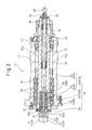
- Figs. 1 and 2 are illustrations showing a spindle head device 10 according to a first embodiment, in respective states where different types of tool holders 14A, 14B (generally referred to as a tool holder 14) are retained on a common spindle 12;
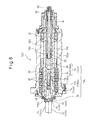
- Fig. 3 is an illustration showing the spindle head device 10 in a state where a tool retaining mechanism 16 is detached from the spindle 12;
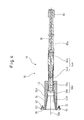
- Fig. 4 is an illustration showing a first unit 18 of the tool retaining mechanism 16 for retaining the first tool holder 14A on the spindle 12;
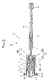
- Fig. 5 is an illustration showing a second unit 20 of the tool retaining mechanism 16 for retaining the second tool holder 14B on the spindle 12.
- the spindle head device 10 is installed in a machine tool equipped with a spindle (so-called a tool spindle) fixedly supporting a tool and rotating, such as a milling machine, a machining center, etc.
- the spindle head device 10 includes the spindle 12, and the tool retaining mechanism 16 detachably retaining the tool holder 14 on the spindle 12.
- the spindle 12 is a hollow tubular member having a center axis 12a and is provided, along the center axis 12a, with a stepped spindle-through-hole 22 penetrating in an axial direction.
- the spindle-through-hole 22 includes a front portion 22a defined at a predetermined length region adjacent to an axial front end (a left end, in the drawing) of the spindle 12 and having a maximum inner diameter, a rear portion 22b defined at a predetermined length region adjacent to an axial rear end (a right end, in the drawing) of the spindle 12 and having an inner diameter smaller than that of the front portion 22a, and an intermediate portion 22c defined at a region between the front portion 22a and the rear portion 22b and having a minimum inner diameter ( Fig. 3 ).
- a plurality of internal threads 24 are formed to be recessed in the axial direction at predetermined positions around the opening end of the front portion 22a of the spindle-through-hole 22.
- the spindle 12 is mounted within a cavity 26a provided in a housing 26 of the spindle head device 10 in a manner rotatable about the axis through a ball bearing 28 and a roller bearing 30.
- the outer surface of the axial front end region of the spindle 12, projecting frontward (leftward, in the drawing) from the cavity 26a of the housing 26, is covered, in a relatively rotatable manner, by a front cover 32 (also serving as an outer ring support of the ball bearing 28) fixed to the front end surface 26b of the housing 26.
- the pulley 34 is disposed, in a relatively rotatable manner, adjacent to the rear side of a rear cover 40 (also serving as an outer ring support of the roller bearing 30) fixed to the rear end surface 26c of the housing 26.
- the spindle 12 having the above configuration is provided by machining in high precision the outer surface thereof adapted to be fitted to the bearings 28, 30.
- the tool holder 14 is provided with a chuck 42 (a general term representing a chuck 42A of the first tool holder 14A and a chuck 42B of the second tool holder 14B) (the chuck may be provided with, e.g., a not-shown chucking element) for chucking a tool (not shown), a flange 44 (a general term representing a flange 44A of the first tool holder 14A and a flange 44B of the second tool holder 14B) adjacent to the chuck 42 and adapted to be grasped by a not-shown grasping section of, e.g., an automatic tool changer (ATC), and a shank 46 (a general term representing a shank 46A of the first tool holder 14A and a shank 46B of the second tool holder 14B) adjacent to the flange 44 and adapted to be retained by the tool retaining mechanism 16.
- a chuck 42 (a general term representing a chuck 42A of the first tool holder 14
- the shank 46A of the first tool holder 14A is configured to have an outer surface in the shape of a circular truncated cone (with 7/24 taper) defined in JIS (JBS) and be provided with a pull stud 48 defined in JIS (JBS) fixed at the distal end of the shank (JIS B6101, B6339; JBS 4001, 4002, etc.).
- the shank 46B of the second tool holder 14B is configured to be provided with a thin-wall, hollow tubular body having an outer surface in the shape of a circular truncated cone (with 1/10 taper) defined in DIN (DIN 69063-5, 69893-5, etc.).
- the tool retaining mechanism 16 includes a tool support member 52 (a general term representing a tool support member 52A for the first tool holder 14A and a tool support member 52B for the second tool holder 14B) provided with a receiving recess 50 (a general term representing a receiving recess 50A for the first tool holder 14A and a receiving recess 50B for the second tool holder 14B) detachably receiving the shank 46 of the tool holder 14; a tool clamp member 54 (a general term representing a tool clamp member 54A for the first tool holder 14A and a tool clamp member 54B for the second tool holder 14B) disposed to be displaceable with respect to the tool support member 52 between an operative position and an inoperative position, as described later, wherein the tool clamp member 54, at the operative position, clamps the shank 46 of the tool holder 14 and fixedly holds the shank 46 in the receiving recess 50 of the tool support member 52, and at the inoperative position, releases
- the receiving recess 50A of the tool support member 52A used for the first tool holder 14A has an inner surface in the shape of a circular truncated cone (with 7/24 taper) defined in JIS (JBS) (JIS B6101, B6339; JBS 4001, 4002, etc.).
- JBS JIS B6101, B6339; JBS 4001, 4002, etc.
- the receiving recess 50B of the tool support member 52B used for the second tool holder 14B has an inner surface in the shape of a circular truncated cone (with 1/10 taper) defined in DIN (DIN 69063-5, 69893-5, etc.).
- the tool support member 52 is a hollow tubular member having a center axis 52a and is provided, along the center axis 52a, with the receiving recess 50 defining a front end opening having a maximum inner diameter and formed in a predetermined length region adjacent to an axial front end (a left end, in the drawing) of the member, and along the center axis 52a, with a stepped member-through-hole 58 (a general term representing a member-through-hole 58A of the tool support member 52A and a member-through-hole 58B of the tool support member 52B) penetrating in an axial direction and communicating with a rear end opening of the receiving recess 50.
- a stepped member-through-hole 58 (a general term representing a member-through-hole 58A of the tool support member 52A and a member-through-hole 58B of the tool support member 52B) penetrating in an axial direction and communicating with a rear end opening of the receiving recess 50.
- the member-through-hole 58 includes a rear portion 58a defined in a predetermined length region adjacent to an axial rear end (a right end, in the drawing) of the tool support member 52 and having a minimum inner diameter, and a front portion 58b defined in a region between the receiving recess 50 and the rear portion 58a and having an inner diameter larger than that of the rear portion 58a ( Figs. 4 and 5 ).
- the tool support member 52 is provided, in the axial front end region thereof, with a flange portion 60 formed to project outward in a radial direction.
- a plurality of through-holes 62 are formed in the flange portion 60 at predetermined positions around the front end opening of the receiving recess 50, and bolts 56 as the mounting members 56 are inserted into the respective through-holes 62.
- the tool support member 52 is dimensioned so that the tubular portion thereof other than the flange portion 60 is contained in and snugly fitted within the front portion 22a ( Fig. 3 ) of the spindle-through-hole 22 of the spindle 12.
- the tool support member 52 In a state where the tool support member 52 is properly contained in the front portion 22a of the spindle-through-hole 22, the tool support member 52 is fixed to the spindle 12 by inserting the mounting members (or bolts) 56 into respective through-holes 62 of the flange portion 60 and screwing the formers into the respective internal threads 24 ( Fig. 3 ) formed in the front end surface of the spindle 12.
- the center axis 52a of the tool support member 52 coincides with the center axis 12a of the spindle 12 ( Figs. 1 and 2 ).
- the tool clamp member 54 includes a plurality of movable clamping elements 64 (a general term representing movable clamping elements 64A of the tool clamp member 54A and movable clamping elements 64B of the tool clamp member 54B) contained in the member-through-hole 58 of the tool support member 52 so as to be displaceable in a radial direction, and an actuating element 66 (a general term representing an actuating element 66A of the tool clamp member 54A and an actuating element 66B of the tool clamp member 54B) contained in the rear portion 22b and intermediate portion 22c of the spindle-through-hole 22 of the spindle 12 so as to be displaceable in an axial direction, the actuating element 66 acting to displace the movable clamping elements 64 in the radial direction by the axial displacement of the actuating element.
- movable clamping elements 64 a general term representing movable clamping elements 64A of the tool clamp member 54A and movable clamping elements 64B of the tool clamp member 54B
- the actuating element 66 is a rod-like element having a center axis 66a, and the movable clamping elements 64 are disposed to surround the axial front end (a left end, in the drawing) region of the actuating element and suitably dispersed in a circumferential direction.
- the actuating element 66 is disposed relative to the tool support member 52 with the center axis 66a of the actuating element 66 coinciding with the center axis 52a of the tool support member 52, and in this state, the axial front end region of the actuating element 66 is contained, together with the movable clamping elements 64, in the member-through-hole 58 so as to be displaceable in the axial direction ( Figs. 4 and 5 ).
- the actuating element 66 is driven by a drive mechanism (e.g., a hydraulic cylinder mechanism) provided externally to the spindle head device 10 (a cylinder end piece 68 is shown in Figs. 1 and 2 ), and acts to displace the movable clamping elements 64 between a shank releasing position and a shank clamping position due to the axial displacement of the actuating element 66 in the spindle-through-hole 22.
- the actuating element 66 may be configured by combining two parts with each other, as shown in Figs. 4 and 5 , or alternatively, may be configured as a single unitary part.
- each movable clamping element 64A of the tool clamp member 54A is an arm-like element fixed at the proximal end (a right end, in the drawing) thereof to the actuating element 66A and provided with an inward claw 70 at the distal free end (a left end, in the drawing) thereof, and is capable of bending or deflecting in the radial direction relative to the center axis 66a of the actuating element 66A in a cantilever fashion under the elastic action of the movable clamping element.
- the movable clamping elements 64A are arranged so as to surround the pull stud 48 at the distal end of the shank 46A of the first tool holder 14A received in the receiving recess 50A of the tool support member 52A, in a state where the respective distal end regions of the movable clamping elements project by a predetermined length from the front end of the actuating element 66A ( Fig. 1 ).
- the movable clamping elements 64A elastically bend to rock in the radial direction in accordance with the axial displacement of the actuating element 66A, and make the distal-end claws 70 engage with a shoulder surface 72 ( Fig. 6A ) formed on the outer surface of the pull stud 48 from the outside of the pull stud, so that the movable clamping elements 64A clamp the pull stud 48, as described later.
- each movable clamping element 64B of the tool clamp member 54B is an arm-like element provided with an outward claw 74 at the front end (a left end, in the drawing) thereof and a bulging portion 76 at the rear end (a right end, in the drawing) thereof, and is capable of shifting, without being deformed, in the radial direction relative to the center axis 66a of the actuating element 66B substantially in a parallel translation manner.
- the movable clamping elements 64B are arranged so that the respective front end regions thereof are inserted into the inner cavity of the shank 46B of the second tool holder 14B received in the receiving recess 50B of the tool support member 52B, in a state where the respective radially inner surface of the movable clamping elements face to the outer surface of a cam element 78 provided at the front end of the actuating element 66B ( Fig. 2 ).
- the movable clamping elements 64B individually shift in parallel translation in the radial direction in accordance with the axial displacement of the actuating element 66B, and make the front-end claws 74 engage with a shoulder surface 80 ( Fig. 7A ) formed on the inner surface of the shank 46B from the inside of the shank, so that the movable clamping elements 64B clamp the shank 46B, as described later.
- the tool retaining mechanism 16 further includes a biasing member 82 contained in the rear portion 22b ( Fig. 3 ) of the spindle-through-hole 22 of the spindle 12 and elastically biasing the tool clamp member 54 from the inoperative position to the operative position, and a locking member 84 fixedly disposed relative to the spindle 12 and preventing the biasing member 82 from separating from the spindle-through-hole 22.
- the biasing member 82 can be commonly used to obtain clamping force, and even when the tool retaining mechanism is detached from the spindle 12, the biasing member 82 can be prevented from separating from the spindle-through-hole 22.
- the illustrated biasing member 82 is constituted, by way of example, from a plurality of coned-disc springs stacked in the axial direction and disposed to surround the actuating element 66 of the tool clamp member 54.
- the stack of the coned-disc springs 82 is supported at the axial front end (a left end, in the drawing) thereof on a shoulder surface between the rear portion 22b and the intermediate portion 22c of the spindle-through-hole 22 and at the axial rear end (a right end, in the drawing) thereof on a spring seat 86 attached to the axial rear end region of the actuating element 66, and is held in the rear portion 22b of the spindle-through-hole 22 by a nut 88 secured to the axial rear end of the actuating element 66.
- the spring seat 86 attached to the actuating element 66 has an outer diameter approximate to an inner diameter of the rear portion 22b of the spindle-through-hole 22, and the nut 88 secured to the actuating element 66 has an outer diameter smaller than the outer diameter of the spring seat 86.
- the locking member 84 is an annular plate-like member fixed to the axial rear end surface (a right end surface, in the drawing) of the spindle 12, and is provided with a center opening 84a having a diameter slightly larger than the outer diameter of the nut 88 secured to the actuating element 66 and smaller than the outer diameter of the spring seat 86 attached to the actuating element 66 ( Fig. 3 ).
- the locking member 84 permits the axial displacement of the actuating element 66 and nut 88, caused by the driving operation of the drive mechanism 68, in a state where the tool retaining mechanism 16 is properly incorporated in the spindle 12, whereas the locking member 84 engages with the spring seat 86 so as to prevent the biasing member 82 from separating from the spindle-through-hole 22, in a state where the tool retaining mechanism 16 is detached from the spindle 12 ( Fig. 3 ). It should be noted that, when the tool holder 14 is not retained by the tool retaining mechanism 16, the locking member 84 also functions to prevent the unintended rearward movement of the actuating element 66.
- the tool retaining mechanism 16 includes, in a mutually interchangeable manner, a first unit 18 ( Fig. 4 ) including the first tool support member 52A provided with the receiving recess 50A for the first tool holder 14A and the first tool clamp member 54A carrying out a first displacement motion between the operative position and the inoperative position (i.e., the axial displacement of the actuating element 66A and the radial rocking displacement of the movable clamping elements 64A), and a second unit 20 ( Fig.
- the first unit 18 and the second unit 20 are handled and stored in a state where the respective tool support members 52A, 52B and the respective tool clamp members 54A, 54B are combined with each other as described.
- Each of the first unit 18 and the second unit 20 is mounted to the spindle 12 in such a manner that, in a state where the nut 88 is removed from the rear end of the actuating element 66, the actuating element 66 is inserted through the front end opening of the front portion 22a ( Fig. 3 ) of the spindle-through-hole 22 into the intermediate portion 22c and rear portion 22b ( Fig. 3 ) of the spindle-through-hole 22, and the tool support member 52 is inserted into the front portion 22a of the spindle-through-hole 22.
- the tool support member 53 is fixed to the spindle 12 in such a manner that, in a state where the tool support member 52 and the tool clamp member 54 are properly contained in the spindle-through-hole 22, the mounting members (or bolts) 56 are individually screwed into the internal threads 24 ( Fig. 3 ) in the front end surface of the spindle 12. Thereafter, the nut 88 is attached to the rear end of the actuating element 66, and thereby the mounting of the first unit 18 or the second unit 20 to the spindle 12 is completed.
- the tool support member 52 and the tool clamp member 54 are disposed coaxially with respect to the spindle 12, and during the axial displacement of the actuating element 66 in the spindle-through-hole 22, the tool support member 52 is held in the spindle-through-hole 22 in a stationary manner.
- the tool clamp member 54A for holding the tool holder 14A is arranged so that, when the actuating element 66A is located at the rear end position of an axial displacement stroke (i.e., when the drive mechanism 68 ( Fig. 1 ) is at rest), the movable clamping elements 64A are drawn into the rear portion 58a of the member-through-hole 58A of the tool support member 52A up to the distal ends of the movable clamping elements.
- the movable clamping elements 64A are subjected to a pressing force from the wall surface of the rear portion 58a of the member-through-hole 58A so as to be elastically deformed radially inward in a cantilever fashion, and thus are maintained in a state where the respective claws 70 are disposed closer to each other.
- the movable clamping elements 64A act to bring the respective claws 70 into engagement with the shoulder surface 72 of the pull stud 48 of the tool holder 14A from the outside of the pull stud, and thus to firmly clamp the pull stud 48 ( Fig. 6A ) under the large elastic biasing force of the biasing member 82 ( Fig. 1 ).
- the tool clamp member 54A is disposed at the operative position (i.e., the movable clamping elements 64A are disposed at shank clamping positions), and thus the tool holder 14A is firmly retained by the tool support member 52A.
- the movable clamping elements 64A are released from the pressing force from the wall surface of the member-through-hole 58A so as to elastically recover and rock radially outward, and thus are shifted so as to displace the respective claws 70 away from each other.
- the movable clamping elements 64A act to displace the respective claws 70 outwardly away from the shoulder surface 72 of the pull stud 48 of the tool holder 14A, and thus to release the pull stud 48 ( Fig. 6B ).
- the tool clamp member 54A is disposed at the inoperative position (i.e., the movable clamping elements 64A are disposed at shank releasing positions), and thus the tool holder 14A is allowed to be attached and detached to and from the receiving recess 50A of the tool support member 52A.
- the tool clamp member 54B for holding the tool holder 14B is arranged so that, when the actuating element 66B is located at the rear end position of an axial displacement stroke (i.e., when the drive mechanism 68 ( Fig. 2 ) is at rest), the movable clamping elements 64B are carried, at the inner surfaces thereof, on the outer surface of the cam element 78 provided at the front end of the actuating element 66B. More specifically, the front-end claw 74 of each movable clamping element 64B runs over the front cam surface 78a of the cam element 78, and generally simultaneously, the rear-end bulging portion 76 runs over the rear cam surface 78b of the cam element 78.
- the movable clamping elements 64B are firmly held between the outer surface of the cam element 78 and the wall surface of the front portion 58b of the member-through-hole 58B of the tool support member 52B, and thus are maintained in a state where the respective claws 74 are disposed away from each other.
- the movable clamping elements 64B act to bring the respective claws 74 into engagement with the shoulder surface 80 of the shank 46B of the tool holder 14B from the inside of the shank, and thus to firmly clamp the shank 46B ( Fig. 7A ) under the large elastic biasing force of the biasing member 82 ( Fig. 2 ).
- the tool clamp member 54B is disposed at the operative position (i.e., the movable clamping elements 64B are disposed at shank clamping positions), and thus the tool holder 14B is firmly retained by the tool support member 52B.
- the movable clamping elements 64B are released from a gap between the outer surface of the cam element 78 and the wall surface of the member-through-hole 58B so as to cause a parallel translation in a radial inward direction, and thus are shifted so as to displace the respective claws 74 close to each other.
- biasing elements i.e., a spring 90 and a pressing piece 92
- biasing elements for applying axially frontward elastic biasing force to the movable clamping element 64B are contained in the front portion 58b of the member-through-hole 58B of the tool support member 52A ( Fig. 5 ).
- the movable clamping elements 64B act to displace the respective claws 74 inwardly away from the shoulder surface 80 of the shank 46B of the tool holder 14B, and thus to release the shank 46B ( Fig. 7B ).
- the tool clamp member 54B is disposed at the inoperative position (i.e., the movable clamping elements 64B are disposed at shank releasing positions), and thus the tool holder 14B is allowed to be attached and detached to and from the receiving recess 50B of the tool support member 52B.
- the tool retaining mechanism 16 is configured to include the tool support member 52 provided with the receiving recess 50 receiving the shank 46 of the tool holder 14, the tool clamp member 54 disposed to be displaceable with respect to the tool support member 52 between the operative position and the inoperative position, and the mounting member 56 detachably mounting the tool support member 52 and the tool clamp member 54 to the spindle 12, so that in the case where several types of tool holders 14 with shanks 46 mutually different in terms of mechanical structures are intended to be used, it is possible to mount, for use, the tool support members 52 provided with the receiving recesses 50 corresponding respectively to the tool holders 14 and the tool clamp members 54 having clamping functions corresponding respectively to the tool holders 14, to the spindle 12 by the mounting member 56, as occasion demands. As a result, it is possible to stably retain the different-type tool holders 14 in an interchangeable manner on the common spindle 12 by the tool retaining mechanisms 16 corresponding respectively to the tool holders 14.
- the shank 46 thereof is not directly retained on the spindle 12, but is retained in the receiving recess 50 of the tool support member 52 detachably mounted to the spindle 12.
- the receiving recess 50 has been worn by repeated tool-changing works, it is only required to replace the tool support member 52 with new one without replacing or renewing the relatively expensive spindle 12. Therefore, according to the spindle head device 10, even if the tool-changing works are highly frequently performed, the spindle 12 needs not be replaced or renewed, and it is thus possible to prevent maintenance cost from increasing.
- the tool retaining mechanism 16 includes, in a mutually interchangeable manner, the first unit 18 and the second unit 20 respectively including the tool support members 52A, 52B and the tool clamp members 54A, 54B, so that it is possible to handle each unit 18, 20 in a state where the tool support member 52A, 52B is combined with the tool clamp member 54A, 54B, and thereby to extremely ease the changing work of the tool retaining mechanism 16 relative to the spindle 12.
- the tool support member 52A, 52B may be provided with a fluid passage 94 for supplying a cleaning fluid or a cooling fluid to the tool holder 14A, 14B ( Figs. 6A and 7A ).
- a second fluid passage 96 for supplying fluid to the fluid passage 94 of the tool support member 52A, 52B may be formed to penetrate in an axial direction in the actuating element 66A, 66B of the tool clamp member 54A, 54B, and the second fluid passage 96 may be connected to a not-shown fluid supply source.
- the fluid discharged from the second fluid passage 96 flows through a space between the movable clamping elements 64A, 64B, and is supplied to the fluid passage 94 of the tool support member 52A, 52B.
- the spindle head device 100 has substantially the same configuration as the spindle head device 10 according to the above-described first embodiment, except that the above-described tool retaining mechanism 16 is constituted as a unit including the biasing member 82. Therefore, corresponding components are denoted by common reference numerals, and the explanations thereof are not repeated.
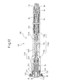
- Figs. 8 and 9 are illustrations showing the spindle head device 100 in respective states where different types of tool holders 14A, 14B are retained on a common spindle 102;
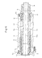
- Fig. 10 is an illustration showing the spindle head device 100 in a state where a tool retaining mechanism 104 is detached from the spindle 102;
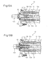
- Figs. 11A and 11B are illustrations showing a first unit 106 of the tool retaining mechanism 104 for retaining the first tool holder 14A on the spindle 102;
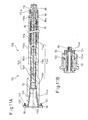
- Fig. 12 is an illustration showing a second unit 108 of the tool retaining mechanism 104 for retaining the second tool holder 14B on the spindle 102.
- the spindle head device 100 includes the spindle 102, and the tool retaining mechanism 104 detachably retaining the tool holder 14 on the spindle 102.
- the spindle 102 is a hollow tubular member having a center axis 102a and is provided, along the center axis 102a, with a stepped spindle-through-hole 110 penetrating in an axial direction.
- a step provided on a spindle inner-wall surface forming the spindle-through-hole 110 is significantly smaller than the step provided on the inner wall surface of the spindle 12 in the above-described spindle head device 10.
- On the front end surface of the spindle 102 a plurality of internal threads 112 are formed to be recessed in the axial direction at predetermined positions around the opening end of the spindle-through-hole 110 ( Fig. 10 ).
- the spindle 102 is mounted within a cavity 26a provided in a housing 26 of the spindle head device 100 in a manner rotatable about the axis through a ball bearing 28 and a roller bearing 30.
- a front cover 32, a pulley 34, a key 36, a nut 38 and a rear cover 40 are provided ( Fig. 10 ).
- the spindle 102 having the above configuration is provided by machining in high precision the outer surface thereof adapted to be fitted to the bearings 28, 30.
- the tool retaining mechanism 104 includes a tool support member 116 (a general term representing a tool support member 116A for the first tool holder 14A and a tool support member 116B for the second tool holder 14B) provided with a receiving recess 114 (a general term representing a receiving recess 114A for the first tool holder 14A and a receiving recess 114B for the second tool holder 14B) detachably receiving the shank 46 of the tool holder 14; a tool clamp member 54 (a general term representing a tool clamp member 54A for the first tool holder 14A and a tool clamp member 54B for the second tool holder 14B) disposed to be displaceable with respect to the tool support member 116 between an operative position and an inoperative position, as described later, wherein the tool clamp member 54, at the operative position, clamps the shank 46 of the tool holder 14 and fixedly holds the shank 46 in the receiving recess 114 of the tool support member 116, and at the inoperative position, releases the
- the receiving recess 114A of the tool support member 116A used for the first tool holder 14A has an inner surface in the shape of a circular truncated cone (with 7/24 taper) defined in JIS (JBS) (JIS B6101, B6339; JBS 4001, 4002, etc.).
- JBS JIS B6101, B6339; JBS 4001, 4002, etc.
- the receiving recess 114B of the tool support member 116B used for the second tool holder 14B has an inner surface in the shape of a circular truncated cone (with 1/10 taper) defined in DIN (DIN 69063-5, 69893-5, etc.).
- the tool support member 116 is a hollow tubular member having a center axis 116a and is provided, along the center axis 116a, with the receiving recess 114 defining a front end opening having a maximum inner diameter and formed in a predetermined length region adjacent to an axial front end (a left end, in the drawing) of the member, and along the center axis 116a, with a stepped member-through-hole 118 (a general term representing a member-through-hole 118A of the tool support member 116A and a member-through-hole 118B of the tool support member 116B) penetrating in an axial direction and communicating with a rear end opening of the receiving recess 114.
- the member-through-hole 118 includes a rear portion 118a defined in a predetermined length region adjacent to an axial rear end (a right end, in the drawing) of the tool support member 116 and having a maximum inner diameter, a front portion 118b defined in a region adjacent to the rear end opening of the receiving recess 114 and having an inner diameter smaller than that of the rear portion 118a, and an intermediate portion 118c defined in a predetermined length region between the rear portion 118a and the front portion 118b and having a minimum inner diameter ( Figs. 11A and 12 ).
- the tool support member 116 is provided, in the axial front end region thereof, with a flange portion 120 formed to project outward in a radial direction.
- a plurality of through-holes 122 are formed in the flange portion 120 at predetermined positions around the front end opening of the receiving recess 114, and bolts 56 as the mounting members 56 are inserted into the respective through-holes 122.
- the tool support member 116 is dimensioned so that the tubular portion thereof other than the flange portion 120 is contained in and snugly fitted within the spindle-through-hole 110 of the spindle 102 over the entire axial length of the spindle-through-hole 110.
- the tool support member 116 is fixed to the spindle 102 by inserting the mounting members (or bolts) 56 into respective through-holes 122 of the flange portion 120 and screwing the formers into the respective internal threads 112 ( Fig 10 ) formed in the front end surface of the spindle 102.
- the center axis 116a of the tool support member 116 coincides with the center axis 102a of the spindle 102 ( Figs. 8 and 9 ).
- the tool support member 116 can be detached from the spindle 102.
- the tool clamp member 54 includes a plurality of movable clamping elements 64 (a general term representing movable clamping elements 64A of the tool clamp member 54A and movable clamping elements 64B of the tool clamp member 54B) contained in the member-through-hole 118 of the tool support member 116 so as to be displaceable in a radial direction, and an actuating element 66 (a general term representing an actuating element 66A of the tool clamp member 54A and an actuating element 66B of the tool clamp member 54B) contained in the member-through-hole 118 of the tool support member 116 so as to be displaceable in an axial direction, the actuating element 66 acting to displace the movable clamping elements 64 in the radial direction by the axial displacement of the actuating element.
- movable clamping elements 64 a general term representing movable clamping elements 64A of the tool clamp member 54A and movable clamping elements 64B of the tool clamp member 54B
- the actuating element 66 is disposed relative to the tool support member 116 with the center axis 66a of the actuating element 66 coinciding with the center axis 116a of the tool support member 116, and in this state, is contained together with the movable clamping elements 64 in the member-through-hole 118.
- the actuating element 66 is driven by a drive mechanism (e.g., a hydraulic cylinder mechanism) 68 ( Fig. 1 ) provided externally to the spindle head device 100, and acts to displace the movable clamping elements 64 between a shank releasing position and a shank clamping position due to the axial displacement of the actuating element 66 in the member-through-hole 118.
- a drive mechanism e.g., a hydraulic cylinder mechanism
- the configuration of the tool clamp member 54 of the tool retaining mechanism 104 (including a tool-shank clamping/releasing operation) is similar to the configuration of the tool clamp member 54 of the tool retaining mechanism 16 in the above-described spindle head device 10.
- the tool retaining mechanism 104 further includes a biasing member 82 contained in the rear portion 118a ( Fig. 3 ) of the member-through-hole 118 of the tool support member 116 and elastically biasing the tool clamp member 54 from the inoperative position to the operative position, and a locking member 124 fixedly disposed relative to the tool support member 116 and preventing the biasing member 82 from separating from the member-through-hole 118.
- the tool retaining mechanism 104 including the biasing member 82 can be readily replaced, and even when the tool retaining mechanism 104 is detached from the spindle 102, the biasing member 82 can be prevented from separating from the member-through-hole 118.
- the illustrated biasing member 82 is constituted, by way of example, from a plurality of coned-disc springs stacked in the axial direction and disposed to surround the actuating element 66 of the tool clamp member 54.
- the stack of the coned-disc springs 82 is supported at the axial front end (a left end, in the drawing) thereof on a shoulder surface between the rear portion 118a and the intermediate portion 118c of the member-through-hole 118 and at the axial rear end (a right end, in the drawing) thereof on a spring seat 86 attached to the axial rear end region of the actuating element 66, and is held in the rear portion 118a of the member-through-hole 118 by a nut 88 secured to the axial rear end of the actuating element 66.
- the spring seat 86 attached to the actuating element 66 has an outer diameter approximate to an inner diameter of the rear portion 118a of the member-through-hole 118, and the nut 88 secured to the actuating element 66 has an outer diameter smaller than the outer diameter of the spring seat 86.
- the locking member 124 is a tubular member fixed adjacent to the rear end opening of the member-through-hole 118, and is provided with a center opening 124a having a diameter slightly larger than the outer diameter of the nut 88 secured to the actuating element 66 and smaller than the outer diameter of the spring seat 86 attached to the actuating element 66.
- the locking member 124 permits the axial displacement of the actuating element 66 and nut 88, caused by the driving operation of the drive mechanism 68 ( Fig. 1 ), in a state where the tool retaining mechanism 104 is properly incorporated in the spindle 102, whereas the locking member 124 engages with the spring seat 86 so as to prevent the biasing member 82 from separating from the member-through-hole 118, in a state where the tool retaining mechanism 104 is detached from the spindle 102.
- the locking member 124 when the tool holder 14 is not retained by the tool retaining mechanism 104, the locking member 124 also functions to prevent the unintended rearward movement of the actuating element 66.
- lateral holes 86a, 116b are formed respectively in the spring seat 86 and the tool support member 116, into which holding pins (not shown) are respectively inserted for temporarily holding the biasing member 82 in the member-through-hole 118, until the locking member 124 is attached to the rear end of the member-through-hole 118 in the assembling process of the tool retaining mechanism 104.
- the tubular locking member 124 in place of the tubular locking member 124 ( Fig.
- a cap-like locking member 124' ( Fig. 11B ) adapted to be secured to the spindle 102 may be employed.
- the cap-like locking member 124' is provided with a center opening 124a' similar to the center opening 124a of the tubular locking member 124.
- the tool retaining mechanism 104 includes, in a mutually interchangeable manner, a first unit 106 ( Fig. 11 ) including the first tool support member 116A provided with the receiving recess 114A for the first tool holder 14A and the first tool clamp member 54A carrying out a first displacement motion between the operative position and the inoperative position (i.e., the axial displacement of the actuating element 66A and the radial rocking displacement of the movable clamping elements 64A), and a second unit 108 ( Fig.
- the first unit 106 and the second unit 108 are handled and stored in a state where the respective tool support members 116A, 116B and the respective tool clamp members 54A, 54B are combined with each other as described.
- Each of the first unit 106 and the second unit 108 is mounted to the spindle 102 in such a manner that the tool support member 116A, 116B containing the tool clamp member 54A, 54B and the biasing member 82 in the member-through-hole 118A, 118B is inserted through the front end opening of the spindle-through-hole 110 into the spindle-through-hole 110. Further, as described, the tool support member 116 is fixed to the spindle 102 in such a manner that, in a state where the tool support member 116 is properly contained in the spindle-through-hole 110, the mounting members (or bolts) 56 are individually screwed into the internal threads 112 ( Fig. 10 ) in the front end surface of the spindle 102. Thereby, the mounting of the first unit 106 or the second unit 108 to the spindle 102 is completed.
- the tool support member 116 and the tool clamp member 54 are disposed coaxially with respect to the spindle 102, and during the axial displacement of the actuating element 66 in the member-through-hole 118, the tool support member 116 is held in the spindle-through-hole 110 in a stationary manner.
- the spindle head device 100 having above-described configuration, it is possible to achieve several effects equivalent to those achieved by the spindle head device 10. More specifically, in the case where several types of tool holders 14 with shanks 46 mutually different in terms of mechanical structures are intended to be used, it is possible to mount, for use, the tool support members 116 provided with the receiving recesses 114 corresponding respectively to the tool holders 14 and the tool clamp members 54 having clamping functions corresponding respectively to the tool holders 14, to the spindle 102 by the mounting member 56, as occasion demands. As a result, it is possible to stably retain the different-type tool holders 14 in an interchangeable manner on the common spindle 102 by the tool retaining mechanisms 104 corresponding respectively to the tool holders 14.
- the shank 46 thereof is not directly retained on the spindle 102, but is retained in the receiving recess 114 of the tool support member 116 detachably mounted to the spindle 102.
- the receiving recess 114 has been worn by repeated tool-changing works, it is only required to replace the tool support member 116 with new one without replacing or renewing the relatively expensive spindle 102. Therefore, according to the spindle head device 100, even if the tool-changing works are highly frequently performed, the spindle 102 needs not be replaced or renewed, and it is thus possible to prevent maintenance cost from increasing.
- the tool retaining mechanism 104 includes, in a mutually interchangeable manner, the first unit 106 and the second unit 108 respectively including the tool support members 116A, 116B and the tool clamp members 54A, 54B, so that it is possible to handle each unit 106, 108 in a state where the tool support member 116A, 116B is combined with the tool clamp member 54A, 54B, and thereby to extremely ease the changing work of the tool retaining mechanism 104 relative to the spindle 102.
- each unit 106, 108 is configured such that the tool support member 116A, 116B contains both the tool clamp member 54A, 54B and the biasing member 82, and thus the exchanging work of the tool retaining mechanism 104 relative to the spindle 102 is further simplified.
- the units 106, 108 individually contain the biasing members 82, and therefore, the unit configuration of the spindle device 10, in which the biasing member 82 can be commonly used, has an advantage in terms of cost. Further, the configuration of the spindle head device 10 provides another advantage in downsizing the tool support member 52.
- the tool support member 116A, 116B may also be provided with a fluid passage 126 for supplying a cleaning fluid or a cooling fluid to the tool holder 14A, 14B.
- the fluid may also be supplied through a second fluid passage 96 formed in the actuating element 66A, 66B of the tool clamp member 54A, 54B to the fluid passage 126 of the tool support member 116A, 116B.
- Figs. 13A to 14B respectively show the modifications of the spindle head devices 10, 100 according to the first and second embodiments.
- the spindle 12 may be provided, in a region (i.e., the front portion 22a) adjacent to the axial front end (a left end, in the drawing) of the spindle-through-hole 22, with a fitting surface 128 having a tapered shape with a diameter thereof increasing toward the front end opening about the center axis 12a.
- the spindle 102 may be provided, in a region adjacent to the axial front end (a left end, in the drawing) of the spindle-through-hole 110, with a fitting surface 132 having tapered shape with a diameter thereof increasing toward the front end opening.
- the tool support member 116A ( Fig. 14A ), 116B ( Fig. 14B ) is provided, in the axial front end region, with an outer surface 134 with a diameter thereof increasing in a tapering rate identical to the tapering rate of the fitting surface 132 toward the flange portion 120.
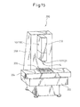
- Fig. 15 shows a machine tool 200, which can be equipped with the spindle head device 10, 100 having the above-described configuration.
- the machine tool 200 has, by way of example, a configuration of a vertical machining center, and includes a bed 202, a table 204 mounted on the bed 202 in a horizontally movable manner, a workpiece pallet 206 mounted on the table 204, a column 208 uprightly standing on the bed 202 at the lateral side of the table 204, and a slide 210 mounted on the front surface of the column 208 in a vertically movable manner, wherein the spindle head device 10, 100 according to the first or second embodiment is installed in the slide 210.
- the machine tool 200 further includes a not-shown automatic tool changer (ATC), so that a tool holder 14 supporting a tool is detachably attached to the spindle 12, 102 of the spindle head device 10, 100 by the ATC.
- ATC automatic tool changer
- the machine tool 200 including the spindle head device 10, 100 capable of stably retaining, in an interchangeable manner, several types of tool holders 14 with shanks 46 mutually different in terms of mechanical structures on the common spindle 12, 102 by the corresponding tool retaining mechanism 16, 104 ( Fig. 1 , Fig. 8 ), as already described, it is possible to prevent equipment cost from increasing and maintenance and management from becoming complicated. Also, in the machine tool 200, even if the receiving recess 50, 114 ( Fig. 1 , Fig. 8 ) of the spindle head device 10, 100, receiving and retaining the shank 46 of the tool holder 14, is worn, the spindle 12, 102 needs not be replaced or renewed, and it is thus possible to prevent maintenance cost from increasing.
Landscapes
- Engineering & Computer Science (AREA)
- Mechanical Engineering (AREA)
- Jigs For Machine Tools (AREA)
- Gripping On Spindles (AREA)
- Auxiliary Devices For Machine Tools (AREA)
- Turning (AREA)
- Automatic Tool Replacement In Machine Tools (AREA)
Description
- The present invention relates to a spindle head device installed in a machine tool and including a tool spindle. The present invention also relates to a machine tool equipped with a spindle head device including a tool spindle.
- A machine tool (e.g., a milling machine, a machining center, etc.) provided with a spindle (a so-called tool spindle) for fixedly supporting a tool and rotating, is configured such that various cutting operations can be carried out by selecting a suitable tool from among several types of tools respectively fitted to tool holders and attaching it to an axial end of the spindle (hereinafter referred to as a spindle nose) in an exchangeable manner. To this end, generally, a machine tool is provided, inside a spindle head device including a tool spindle, with a tool retaining mechanism for detachably retaining respective tool holders on the spindle nose.
- A tool holder is provided with a chuck for chucking a tool, a shank adapted to be received and held in the spindle nose, and a flange adapted to be grasped by an automatic tool changer (ATC) and usually provided between the chuck and the shank. Correspondingly, the spindle nose is provided with a receiving recess for detachably receiving the shank (also referred to as a tool shank) of the tool holder. On the other hand, the tool retaining mechanism includes a movable clamping element for releasably clamping the tool shank and an actuating element for displacing the movable clamping element between a shank releasing position and a shank clamping position, and is accommodated in an axial through-hole formed in the spindle. The actuating element of the tool retaining mechanism is driven by a drive mechanism (e.g., a hydraulic cylinder mechanism) provided outside the spindle head device, and acts to displace the movable clamping element in accordance with the axial displacement of the actuating element in the through-hole of the spindle.
- In the machine tool as described above, the configuration of the shank of the tool holder and the corresponding configuration of the spindle nose of the spindle are standardized by standards such as JIS (Japan Industrial Standard), DIN (Deutsche Industrie Normen), JBS (Japan Bench Machine Tool Builders Association Standard), etc. For example, a tool shank standardized by JIS or JBS is configured to have an outer surface in the shape of a circular truncated cone (with 7/24 taper) and be provided with a rod-like element, referred to as a pull stud, fixed at the distal end of the tool shank, while a corresponding spindle nose is provided with a shank receiving recess having an inner surface in the shape of a circular truncated cone (with 7/24 taper) (JIS B6101, B6339; JBS 4001, 4002, etc.). On the other hand, a tool shank standardized by DIN is configured to be provided with a thin-wall, hollow tubular body having an outer surface in the shape of a circular truncated cone (with 1/10 taper), while a corresponding spindle nose is provided with a shank receiving recess having an inner surface in the shape of a circular truncated cone (with 1/10 taper) (DIN 69063-5, 69893-5, etc.).
- A tool retaining mechanism for retaining a tool holder complying with JIS (JBS) on a spindle nose, is configured to clamp the pull stud at the distal end of the tool shank received in the shank receiving recess by a plurality of movable clamping elements provided to be disposed around the pull stud, in which the movable clamping elements are moved in a radial direction under the operation of the actuating element and thus are engaged with a shoulder surface of the pull stud from the outside thereof. In contrast, a tool retaining mechanism for retaining a tool holder complying with DIN on a spindle nose, is configured to clamp the tool shank received in the shank receiving recess by a plurality of movable clamping elements provided to be inserted into the hollow interior portion of the tool shank, in which the movable clamping elements are moved in a radial direction under the operation of the actuating element and thus are engaged with a shoulder surface of the tool shank from the inside thereof. In this connection, the configurations of the tool holder, the spindle nose and the tool retaining mechanism, complying with JIS (JBS), are described in, for example, Japanese Unexamined Patent Publication (Kokai) No.
9-314404 JP-A-9-314404 5-220607 JP-A-5-220607 - As described above, for a conventional machine tool provided with a tool spindle, there are several standards different in terms of mechanical structures and incompatible with each other, regarding the configurations of a tool holder, a spindle nose and a tool retaining mechanism. Thus, when a user of a machine tool intends to use different types of tool holders complying with incompatible standards, it is necessary for the user to prepare different types of machine tools provided respectively with spindle head devices for exclusive use, each spindle head device including a spindle and a tool retaining mechanism, complying with each standard. The user generally tends to store various types of tools in a state where they are attached to tool holders, so that in a case where, for example, the user intends to suitably select and use the mechanical configurations respectively complying with JIS and DIN while considering several requirements such as a machining precision, a tool life, an operating noise, etc., it is also necessary to permanently prepare machine tools respectively complying with JIS and DIN, even for the same type of tools. Therefore, in this case, equipment cost may increase, and maintenance and management may be complicated.
- A conventional machine tool provided with a tool spindle is also configured such that, in each standard, a shank of a tool holder is received and retained in a shank receiving recess at a spindle nose. Therefore, repeated tool-changing works may cause a wear of the shank receiving recess of the spindle nose, and in such a case, the spindle needs to be replaced with new one. In this connection, the spindle is usually required to be machined in high precision at the inner surface thereof including the shank receiving recess and the outer surface thereof adapted to be fitted into a bearing unit, and in recent years, there is an increasing requirement of forming a fluid passage for supplying cleaning fluid or cooling fluid so as to penetrate through the spindle, so that the spindle has now become relatively expensive among all components of a machine tool. Therefore, if the tool-changing is frequently carried out, the replacement of such an expensive spindle with new one may result higher maintenance costs.
-
DE 103 17 097 A1 discloses a device for clamping tools or workpieces comprising coupling shafts of varying geometry onto a shaft assembly, the shaft assembly comprising a receiving bush that is mounted to rotate about a longitudinal axis and a clamping element that can be rotated with said bush and displaced in relation to the bush along the longitudinal axis. An adapter bush is provide that can be attached to the receiving bush and an adapter clamping member can be coupled to the clamping element in order to adapt the device to the coupling shaft of the tool or workpiece that is to be clamped onto the shaft assembly. -
US 2005/0220556 A1 discloses a spindle head device comprising the features of the preamble ofclaim 1. - It is an object of the present invention to provide a spindle head device installed in a machine tool, which is a multipurpose type capable of stably retaining, in an exchangeable manner, several types of tool holders provided with shanks mutually different in terms of mechanical structures, on a common spindle by tool retaining mechanisms corresponding respectively to the tool holders, and thus capable of preventing equipment cost from increasing and maintenance and management from becoming complicated.
- It is another object of the present invention to provide a spindle head device installed in a machine tool, which can eliminate the need of replacing or renewal of a spindle even when a shank receiving recess for receiving a shank of a tool holder is worn, and thus can prevent maintenance cost from increasing.
- It is still another object of the present invention to provide a general-purpose machine tool which includes a spindle head device capable of stably retaining, in an exchangeable manner, several types of tool holders provided with shanks mutually different in terms of mechanical structures, on a common spindle by tool retaining mechanisms corresponding respectively to the tool holders, and which can thereby prevent equipment cost from increasing and maintenance and management from becoming complicated.
- It is a still further object of the present invention to provide a machine tool which can eliminate the need of replacing or renewal of a spindle even when a shank receiving recess provided in a spindle head device for receiving a shank of a tool holder is worn, and thus can prevent maintenance cost from increasing.
- In order to accomplish the above objects, the present invention provides a spindle head device for a machine tool comprising a spindle; and a tool retaining mechanism detachably retaining a tool holder on the spindle; the tool retaining mechanism comprising: a tool support member provided with a receiving recess detachably receiving a shank of a tool holder; a tool clamp member disposed to be displaceable with respect to the tool support member between an operative position and an inoperative position, the tool clamp member, at the operative position, clamping the shank of the tool holder and fixedly holding the shank in the receiving recess of the tool support member, and at the inoperative position, releasing the shank and allowing the tool holder to be attached and detached to and from the receiving recess; and a mounting member detachably mounting the tool support member and the tool clamp member to the spindle.
- The spindle is provided with a spindle-through-hole penetrating in an axial direction; the tool support member is provided with a member-through-hole penetrating in an axial direction and communicating with the receiving recess, and is dimensioned so as to be contained in the spindle-through-hole of the spindle over an entire axial length of the spindle-through-hole; and the tool clamp member comprises a movable clamping element contained in the member-through-hole of the tool support member to be displaceable in a radial direction, and an actuating element contained in the member-through-hole of the tool support member to be displaceable in an axial direction, the actuating element displacing the movable clamping element in the radial direction by an axial displacement of the actuating element.
- The spindle may be provided, in a region adjacent to one axial end of the spindle-through-hole, with a fitting surface having a tapered shape with a diameter thereof increasing toward the one axial end, the fitting surface acting to support in a centering manner the tool support member.
- The tool support member may be provided with a fluid passage for supplying a cleaning fluid or a cooling fluid to a tool holder.
- The tool retaining mechanism may comprise, in a mutually interchangeable manner, a first unit including a first one of the tool support member provided with a first one of the receiving recess and a first one of the tool clamp member carrying out a first displacement motion between the operative position and the inoperative position; and a second unit including a second one of the tool support member provided with a second one of the receiving recess, different in shape from the first one of receiving recess, and a second one of the tool clamp member carrying out a second displacement motion, different from the first displacement motion, between the operative position and the inoperative position.
- The present invention further provides a machine tool comprising a spindle head device having the above-described configuration.
- The above and other objects, features and advantages of the present invention will become more apparent from the following description in connection with the accompanying drawings, in which:
-
Fig. 1 is a sectional view showing a spindle head device according to a first embodiment which is not part of the present invention, in a state where a first tool holder is retained on a common spindle; -
Fig. 2 is a sectional view showing the spindle head device ofFig. 1 , in a state where a second tool holder is retained on the common spindle; -
Fig. 3 is a sectional view showing the spindle head device ofFig. 1 , in a state where a tool retaining mechanism is detached from the spindle; -
Fig. 4 is a sectional view showing, in the spindle head device ofFig. 1 , a first unit of the tool retaining mechanism for retaining a first tool holder on the spindle; -
Fig. 5 is a sectional view showing, in the spindle head device ofFig. 1 , a second unit of the tool retaining mechanism for retaining a second tool holder on the spindle; -
Figs. 6A and 6B are partial enlarged sectional views explaining tool-shank clamping/releasing operations performed for the first tool holder by a tool clamp member of the tool retaining mechanism in the spindle head device ofFig. 1 , and showing respective states at an operative position and an inoperative position; -
Figs. 7A and 7B are partial enlarged sectional views explaining tool-shank clamping/releasing operations performed for the second tool holder by a tool clamp member of the tool retaining mechanism in the spindle head device ofFig. 1 , and showing respective states at the operative position and the inoperative position; -
Fig. 8 is a sectional view showing a spindle head device according to a second embodiment which is part of the present invention, in a state where a first tool holder is retained on a common spindle; -
Fig. 9 is a sectional view showing the spindle head device ofFig. 8 , in a state where a second tool holder is retained on the common spindle; -
Fig. 10 is a sectional view showing the spindle head device ofFig. 8 , in a state where a tool retaining mechanism is detached from the spindle; -
Fig. 11A is a sectional view showing, in the spindle head device ofFig. 8 , a first unit of the tool retaining mechanism for retaining a first tool holder on the spindle; -
Fig. 11B is a sectional view showing a modification of a locking member in the spindle head device ofFig. 8 ; -
Fig. 12 is a sectional view showing, in the spindle head device ofFig. 8 , a second unit of the tool retaining mechanism for retaining a second tool holder on the spindle; -
Figs. 13A and 13B are sectional views showing a modification of the spindle head device ofFig. 1 , and respectively showing a state where the first tool holder is retained and a state where the second tool holder is retained; -
Figs. 14A and 14B are sectional views showing a modification of the spindle head device ofFig. 8 , and respectively showing a state where the first tool holder is retained and a state where the second tool holder is retained; and -
Fig. 15 is an illustration showing a machine tool capable of installing the spindle head device ofFig. 1 orFig. 8 . - In the drawings, same or similar components are denoted by common reference numerals.
- Referring to the drawings,
Figs. 1 and2 are illustrations showing aspindle head device 10 according to a first embodiment, in respective states where different types oftool holders common spindle 12;Fig. 3 is an illustration showing thespindle head device 10 in a state where atool retaining mechanism 16 is detached from thespindle 12;Fig. 4 is an illustration showing afirst unit 18 of thetool retaining mechanism 16 for retaining thefirst tool holder 14A on thespindle 12; andFig. 5 is an illustration showing asecond unit 20 of thetool retaining mechanism 16 for retaining thesecond tool holder 14B on thespindle 12. Thespindle head device 10 is installed in a machine tool equipped with a spindle (so-called a tool spindle) fixedly supporting a tool and rotating, such as a milling machine, a machining center, etc. - As shown in
Figs. 1 and2 , thespindle head device 10 includes thespindle 12, and thetool retaining mechanism 16 detachably retaining thetool holder 14 on thespindle 12. Thespindle 12 is a hollow tubular member having acenter axis 12a and is provided, along thecenter axis 12a, with a stepped spindle-through-hole 22 penetrating in an axial direction. The spindle-through-hole 22 includes afront portion 22a defined at a predetermined length region adjacent to an axial front end (a left end, in the drawing) of thespindle 12 and having a maximum inner diameter, arear portion 22b defined at a predetermined length region adjacent to an axial rear end (a right end, in the drawing) of thespindle 12 and having an inner diameter smaller than that of thefront portion 22a, and anintermediate portion 22c defined at a region between thefront portion 22a and therear portion 22b and having a minimum inner diameter (Fig. 3 ). On the front end surface of thespindle 12, a plurality ofinternal threads 24 are formed to be recessed in the axial direction at predetermined positions around the opening end of thefront portion 22a of the spindle-through-hole 22. - The
spindle 12 is mounted within acavity 26a provided in ahousing 26 of thespindle head device 10 in a manner rotatable about the axis through aball bearing 28 and aroller bearing 30. The outer surface of the axial front end region of thespindle 12, projecting frontward (leftward, in the drawing) from thecavity 26a of thehousing 26, is covered, in a relatively rotatable manner, by a front cover 32 (also serving as an outer ring support of the ball bearing 28) fixed to thefront end surface 26b of thehousing 26. Apulley 34 connected to a not-shown driving source for the rotation of the spindle, such as a servo motor, is fixed to the outer surface of the axial rear end region of thespindle 12, projecting rearward (rightward, in the drawing) from thecavity 26a of thehousing 26, by using a key 36 and a nut 38 (Fig. 3 ). Thepulley 34 is disposed, in a relatively rotatable manner, adjacent to the rear side of a rear cover 40 (also serving as an outer ring support of the roller bearing 30) fixed to therear end surface 26c of thehousing 26. Thespindle 12 having the above configuration is provided by machining in high precision the outer surface thereof adapted to be fitted to thebearings - As shown in
Figs. 1 and2 , thetool holder 14 is provided with a chuck 42 (a general term representing achuck 42A of thefirst tool holder 14A and achuck 42B of thesecond tool holder 14B) (the chuck may be provided with, e.g., a not-shown chucking element) for chucking a tool (not shown), a flange 44 (a general term representing aflange 44A of thefirst tool holder 14A and aflange 44B of thesecond tool holder 14B) adjacent to thechuck 42 and adapted to be grasped by a not-shown grasping section of, e.g., an automatic tool changer (ATC), and a shank 46 (a general term representing ashank 46A of thefirst tool holder 14A and ashank 46B of thesecond tool holder 14B) adjacent to theflange 44 and adapted to be retained by thetool retaining mechanism 16. - The
shank 46A of thefirst tool holder 14A is configured to have an outer surface in the shape of a circular truncated cone (with 7/24 taper) defined in JIS (JBS) and be provided with apull stud 48 defined in JIS (JBS) fixed at the distal end of the shank (JIS B6101, B6339; JBS 4001, 4002, etc.). On the other hand, theshank 46B of thesecond tool holder 14B is configured to be provided with a thin-wall, hollow tubular body having an outer surface in the shape of a circular truncated cone (with 1/10 taper) defined in DIN (DIN 69063-5, 69893-5, etc.). - As shown in
Figs. 1 and2 , thetool retaining mechanism 16 includes a tool support member 52 (a general term representing atool support member 52A for thefirst tool holder 14A and atool support member 52B for thesecond tool holder 14B) provided with a receiving recess 50 (a general term representing a receivingrecess 50A for thefirst tool holder 14A and a receivingrecess 50B for thesecond tool holder 14B) detachably receiving theshank 46 of thetool holder 14; a tool clamp member 54 (a general term representing atool clamp member 54A for thefirst tool holder 14A and atool clamp member 54B for thesecond tool holder 14B) disposed to be displaceable with respect to thetool support member 52 between an operative position and an inoperative position, as described later, wherein thetool clamp member 54, at the operative position, clamps theshank 46 of thetool holder 14 and fixedly holds theshank 46 in the receivingrecess 50 of thetool support member 52, and at the inoperative position, releases theshank 46 and allows thetool holder 14 to be attached and detached to and from the receivingrecess 50; and a mountingmember 56 detachably mounting thetool support member 52 and thetool clamp member 54 to thespindle 12. - The receiving
recess 50A of thetool support member 52A used for thefirst tool holder 14A has an inner surface in the shape of a circular truncated cone (with 7/24 taper) defined in JIS (JBS) (JIS B6101, B6339; JBS 4001, 4002, etc.). On the other hand, the receivingrecess 50B of thetool support member 52B used for thesecond tool holder 14B has an inner surface in the shape of a circular truncated cone (with 1/10 taper) defined in DIN (DIN 69063-5, 69893-5, etc.). - The
tool support member 52 is a hollow tubular member having acenter axis 52a and is provided, along thecenter axis 52a, with the receivingrecess 50 defining a front end opening having a maximum inner diameter and formed in a predetermined length region adjacent to an axial front end (a left end, in the drawing) of the member, and along thecenter axis 52a, with a stepped member-through-hole 58 (a general term representing a member-through-hole 58A of thetool support member 52A and a member-through-hole 58B of thetool support member 52B) penetrating in an axial direction and communicating with a rear end opening of the receivingrecess 50. The member-through-hole 58 includes arear portion 58a defined in a predetermined length region adjacent to an axial rear end (a right end, in the drawing) of thetool support member 52 and having a minimum inner diameter, and afront portion 58b defined in a region between the receivingrecess 50 and therear portion 58a and having an inner diameter larger than that of therear portion 58a (Figs. 4 and5 ). - As shown in
Figs. 4 and5 , thetool support member 52 is provided, in the axial front end region thereof, with aflange portion 60 formed to project outward in a radial direction. A plurality of through-holes 62 are formed in theflange portion 60 at predetermined positions around the front end opening of the receivingrecess 50, andbolts 56 as the mountingmembers 56 are inserted into the respective through-holes 62. Thetool support member 52 is dimensioned so that the tubular portion thereof other than theflange portion 60 is contained in and snugly fitted within thefront portion 22a (Fig. 3 ) of the spindle-through-hole 22 of thespindle 12. - In a state where the
tool support member 52 is properly contained in thefront portion 22a of the spindle-through-hole 22, thetool support member 52 is fixed to thespindle 12 by inserting the mounting members (or bolts) 56 into respective through-holes 62 of theflange portion 60 and screwing the formers into the respective internal threads 24 (Fig. 3 ) formed in the front end surface of thespindle 12. In this state, thecenter axis 52a of thetool support member 52 coincides with thecenter axis 12a of the spindle 12 (Figs. 1 and2 ). When removing the mounting members (or bolts) 56 from the correspondinginternal threads 24, thetool support member 52 can be detached from thespindle 12. - As shown in
Figs. 1 and2 , thetool clamp member 54 includes a plurality of movable clamping elements 64 (a general term representingmovable clamping elements 64A of thetool clamp member 54A andmovable clamping elements 64B of thetool clamp member 54B) contained in the member-through-hole 58 of thetool support member 52 so as to be displaceable in a radial direction, and an actuating element 66 (a general term representing anactuating element 66A of thetool clamp member 54A and anactuating element 66B of thetool clamp member 54B) contained in therear portion 22b andintermediate portion 22c of the spindle-through-hole 22 of thespindle 12 so as to be displaceable in an axial direction, theactuating element 66 acting to displace themovable clamping elements 64 in the radial direction by the axial displacement of the actuating element. In this configuration, as described later, it is possible to reliably retain thetool holder 14 in the receivingrecess 50 of thetool support member 52 by a relatively simple and downsized structure. - The
actuating element 66 is a rod-like element having acenter axis 66a, and themovable clamping elements 64 are disposed to surround the axial front end (a left end, in the drawing) region of the actuating element and suitably dispersed in a circumferential direction. Theactuating element 66 is disposed relative to thetool support member 52 with thecenter axis 66a of theactuating element 66 coinciding with thecenter axis 52a of thetool support member 52, and in this state, the axial front end region of theactuating element 66 is contained, together with themovable clamping elements 64, in the member-through-hole 58 so as to be displaceable in the axial direction (Figs. 4 and5 ). Theactuating element 66 is driven by a drive mechanism (e.g., a hydraulic cylinder mechanism) provided externally to the spindle head device 10 (acylinder end piece 68 is shown inFigs. 1 and2 ), and acts to displace themovable clamping elements 64 between a shank releasing position and a shank clamping position due to the axial displacement of theactuating element 66 in the spindle-through-hole 22. In this connection, theactuating element 66 may be configured by combining two parts with each other, as shown inFigs. 4 and5 , or alternatively, may be configured as a single unitary part. - As shown in
Fig. 4 , eachmovable clamping element 64A of thetool clamp member 54A is an arm-like element fixed at the proximal end (a right end, in the drawing) thereof to theactuating element 66A and provided with aninward claw 70 at the distal free end (a left end, in the drawing) thereof, and is capable of bending or deflecting in the radial direction relative to thecenter axis 66a of theactuating element 66A in a cantilever fashion under the elastic action of the movable clamping element. Themovable clamping elements 64A are arranged so as to surround thepull stud 48 at the distal end of theshank 46A of thefirst tool holder 14A received in the receivingrecess 50A of thetool support member 52A, in a state where the respective distal end regions of the movable clamping elements project by a predetermined length from the front end of theactuating element 66A (Fig. 1 ). Themovable clamping elements 64A elastically bend to rock in the radial direction in accordance with the axial displacement of theactuating element 66A, and make the distal-end claws 70 engage with a shoulder surface 72 (Fig. 6A ) formed on the outer surface of thepull stud 48 from the outside of the pull stud, so that themovable clamping elements 64A clamp thepull stud 48, as described later. - On the other hand, as shown in
Fig. 5 , eachmovable clamping element 64B of thetool clamp member 54B is an arm-like element provided with anoutward claw 74 at the front end (a left end, in the drawing) thereof and a bulgingportion 76 at the rear end (a right end, in the drawing) thereof, and is capable of shifting, without being deformed, in the radial direction relative to thecenter axis 66a of theactuating element 66B substantially in a parallel translation manner. Themovable clamping elements 64B are arranged so that the respective front end regions thereof are inserted into the inner cavity of theshank 46B of thesecond tool holder 14B received in the receivingrecess 50B of thetool support member 52B, in a state where the respective radially inner surface of the movable clamping elements face to the outer surface of acam element 78 provided at the front end of theactuating element 66B (Fig. 2 ). Themovable clamping elements 64B individually shift in parallel translation in the radial direction in accordance with the axial displacement of theactuating element 66B, and make the front-end claws 74 engage with a shoulder surface 80 (Fig. 7A ) formed on the inner surface of theshank 46B from the inside of the shank, so that themovable clamping elements 64B clamp theshank 46B, as described later. - As shown in
Figs. 1 and2 , thetool retaining mechanism 16 further includes a biasingmember 82 contained in therear portion 22b (Fig. 3 ) of the spindle-through-hole 22 of thespindle 12 and elastically biasing thetool clamp member 54 from the inoperative position to the operative position, and a lockingmember 84 fixedly disposed relative to thespindle 12 and preventing the biasingmember 82 from separating from the spindle-through-hole 22. In this configuration, as described later, when thetool retaining mechanism 16 is changed to another one, the biasingmember 82 can be commonly used to obtain clamping force, and even when the tool retaining mechanism is detached from thespindle 12, the biasingmember 82 can be prevented from separating from the spindle-through-hole 22. - The illustrated biasing
member 82 is constituted, by way of example, from a plurality of coned-disc springs stacked in the axial direction and disposed to surround theactuating element 66 of thetool clamp member 54. The stack of the coned-disc springs 82 is supported at the axial front end (a left end, in the drawing) thereof on a shoulder surface between therear portion 22b and theintermediate portion 22c of the spindle-through-hole 22 and at the axial rear end (a right end, in the drawing) thereof on aspring seat 86 attached to the axial rear end region of theactuating element 66, and is held in therear portion 22b of the spindle-through-hole 22 by anut 88 secured to the axial rear end of theactuating element 66. - As illustrated, the
spring seat 86 attached to theactuating element 66 has an outer diameter approximate to an inner diameter of therear portion 22b of the spindle-through-hole 22, and thenut 88 secured to theactuating element 66 has an outer diameter smaller than the outer diameter of thespring seat 86. The lockingmember 84 is an annular plate-like member fixed to the axial rear end surface (a right end surface, in the drawing) of thespindle 12, and is provided with acenter opening 84a having a diameter slightly larger than the outer diameter of thenut 88 secured to theactuating element 66 and smaller than the outer diameter of thespring seat 86 attached to the actuating element 66 (Fig. 3 ). Thus, the lockingmember 84 permits the axial displacement of theactuating element 66 andnut 88, caused by the driving operation of thedrive mechanism 68, in a state where thetool retaining mechanism 16 is properly incorporated in thespindle 12, whereas the lockingmember 84 engages with thespring seat 86 so as to prevent the biasingmember 82 from separating from the spindle-through-hole 22, in a state where thetool retaining mechanism 16 is detached from the spindle 12 (Fig. 3 ). It should be noted that, when thetool holder 14 is not retained by thetool retaining mechanism 16, the lockingmember 84 also functions to prevent the unintended rearward movement of theactuating element 66. - The
tool retaining mechanism 16 includes, in a mutually interchangeable manner, a first unit 18 (Fig. 4 ) including the firsttool support member 52A provided with the receivingrecess 50A for thefirst tool holder 14A and the firsttool clamp member 54A carrying out a first displacement motion between the operative position and the inoperative position (i.e., the axial displacement of theactuating element 66A and the radial rocking displacement of themovable clamping elements 64A), and a second unit 20 (Fig. 5 ) including the secondtool support member 52B provided with the receivingrecess 50B for thesecond tool holder 14B, different in shape from the receivingrecess 50A, and the secondtool clamp member 54B carrying out a second displacement motion, different from the first displacement motion, between the operative position and the inoperative position (i.e., the axial displacement of theactuating element 66B and the radial parallel-translation displacement of themovable clamping elements 64B). Thefirst unit 18 and thesecond unit 20 are handled and stored in a state where the respectivetool support members tool clamp members - Each of the
first unit 18 and thesecond unit 20 is mounted to thespindle 12 in such a manner that, in a state where thenut 88 is removed from the rear end of theactuating element 66, theactuating element 66 is inserted through the front end opening of thefront portion 22a (Fig. 3 ) of the spindle-through-hole 22 into theintermediate portion 22c andrear portion 22b (Fig. 3 ) of the spindle-through-hole 22, and thetool support member 52 is inserted into thefront portion 22a of the spindle-through-hole 22. Further, as described, the tool support member 53 is fixed to thespindle 12 in such a manner that, in a state where thetool support member 52 and thetool clamp member 54 are properly contained in the spindle-through-hole 22, the mounting members (or bolts) 56 are individually screwed into the internal threads 24 (Fig. 3 ) in the front end surface of thespindle 12. Thereafter, thenut 88 is attached to the rear end of theactuating element 66, and thereby the mounting of thefirst unit 18 or thesecond unit 20 to thespindle 12 is completed. - In a state where the
first unit 18 or thesecond unit 20 is properly mounted to thespindle 12, thetool support member 52 and the tool clamp member 54 (themovable clamping elements 64 and the actuating element 66) are disposed coaxially with respect to thespindle 12, and during the axial displacement of theactuating element 66 in the spindle-through-hole 22, thetool support member 52 is held in the spindle-through-hole 22 in a stationary manner. In order to perform the interchange of thefirst unit 18 and thesecond unit 20, it is only required to take out the mounting members (or bolts) 56 from the correspondinginternal threads 24, remove thenut 88 from the rear end of theactuating element 66, and detach thetool support member 52 and thetool clamp member 54 from thespindle 12. - Referring now to
Figs. 6A to 7B , a tool-shank clamping/releasing operation performed by thetool clamp member 54 of thetool retaining mechanism 16 will be described. - As shown in
Fig. 6A , thetool clamp member 54A for holding thetool holder 14A is arranged so that, when theactuating element 66A is located at the rear end position of an axial displacement stroke (i.e., when the drive mechanism 68 (Fig. 1 ) is at rest), themovable clamping elements 64A are drawn into therear portion 58a of the member-through-hole 58A of thetool support member 52A up to the distal ends of the movable clamping elements. Thereby, themovable clamping elements 64A are subjected to a pressing force from the wall surface of therear portion 58a of the member-through-hole 58A so as to be elastically deformed radially inward in a cantilever fashion, and thus are maintained in a state where therespective claws 70 are disposed closer to each other. - In this operation, if the
shank 46A of thetool holder 14A has been received in the receivingrecess 50A of thetool support member 52A, themovable clamping elements 64A act to bring therespective claws 70 into engagement with theshoulder surface 72 of thepull stud 48 of thetool holder 14A from the outside of the pull stud, and thus to firmly clamp the pull stud 48 (Fig. 6A ) under the large elastic biasing force of the biasing member 82 (Fig. 1 ). In this state, thetool clamp member 54A is disposed at the operative position (i.e., themovable clamping elements 64A are disposed at shank clamping positions), and thus thetool holder 14A is firmly retained by thetool support member 52A. - From the above-described state, when the drive mechanism starts to operate (shown by an arrow in
Fig. 1 ) and displaces theactuating element 66A in an axial frontward direction in the spindle-through-hole 22 (Fig. 1 ) against the biasing force of the biasingmember 82, the distal end regions of themovable clamping elements 64A enter into thefront portion 58b of the member-through-hole 58A of thetool support member 52A. - Thereby, as shown in
Fig. 6B , themovable clamping elements 64A are released from the pressing force from the wall surface of the member-through-hole 58A so as to elastically recover and rock radially outward, and thus are shifted so as to displace therespective claws 70 away from each other. - In this operation, if the
shank 46A of thetool holder 14A has been received in the receivingrecess 50A of thetool support member 52A, themovable clamping elements 64A act to displace therespective claws 70 outwardly away from theshoulder surface 72 of thepull stud 48 of thetool holder 14A, and thus to release the pull stud 48 (Fig. 6B ). In this state, thetool clamp member 54A is disposed at the inoperative position (i.e., themovable clamping elements 64A are disposed at shank releasing positions), and thus thetool holder 14A is allowed to be attached and detached to and from the receivingrecess 50A of thetool support member 52A. - As shown in
Fig. 7A , thetool clamp member 54B for holding thetool holder 14B is arranged so that, when theactuating element 66B is located at the rear end position of an axial displacement stroke (i.e., when the drive mechanism 68 (Fig. 2 ) is at rest), themovable clamping elements 64B are carried, at the inner surfaces thereof, on the outer surface of thecam element 78 provided at the front end of theactuating element 66B. More specifically, the front-end claw 74 of eachmovable clamping element 64B runs over thefront cam surface 78a of thecam element 78, and generally simultaneously, the rear-end bulging portion 76 runs over therear cam surface 78b of thecam element 78. Thereby, themovable clamping elements 64B are firmly held between the outer surface of thecam element 78 and the wall surface of thefront portion 58b of the member-through-hole 58B of thetool support member 52B, and thus are maintained in a state where therespective claws 74 are disposed away from each other. - In this operation, if the
shank 46B of thetool holder 14B has been received in the receivingrecess 50B of thetool support member 52B, themovable clamping elements 64B act to bring therespective claws 74 into engagement with theshoulder surface 80 of theshank 46B of thetool holder 14B from the inside of the shank, and thus to firmly clamp theshank 46B (Fig. 7A ) under the large elastic biasing force of the biasing member 82 (Fig. 2 ). In this state, thetool clamp member 54B is disposed at the operative position (i.e., themovable clamping elements 64B are disposed at shank clamping positions), and thus thetool holder 14B is firmly retained by thetool support member 52B. - From the above-described state, when the drive mechanism starts to operate (shown by an arrow in
Fig. 2 ) and displaces theactuating element 66B in an axial frontward direction in the spindle-through-hole 22 (Fig. 2 ) against the biasing force of the biasingmember 82, themovable clamping elements 64B move relative to thecam element 78 toward the rear end of thecam element 78, whereby the respective front-end claws 74 slide downward on thefront cam surface 78a of thecam element 78, and generally simultaneously, the respective rear-end bulging portions 76 slide downward on therear cam surface 78b of thecam element 78. Thereby, as shown inFig. 7B , themovable clamping elements 64B are released from a gap between the outer surface of thecam element 78 and the wall surface of the member-through-hole 58B so as to cause a parallel translation in a radial inward direction, and thus are shifted so as to displace therespective claws 74 close to each other. In this connection, in order to achieve the parallel translation of eachmovable clamping element 64B, biasing elements (i.e., aspring 90 and a pressing piece 92) for applying axially frontward elastic biasing force to themovable clamping element 64B are contained in thefront portion 58b of the member-through-hole 58B of thetool support member 52A (Fig. 5 ). - In this operation, if the
shank 46B of thetool holder 14B has been received in the receivingrecess 50B of thetool support member 52B, themovable clamping elements 64B act to displace therespective claws 74 inwardly away from theshoulder surface 80 of theshank 46B of thetool holder 14B, and thus to release theshank 46B (Fig. 7B ). In this state, thetool clamp member 54B is disposed at the inoperative position (i.e., themovable clamping elements 64B are disposed at shank releasing positions), and thus thetool holder 14B is allowed to be attached and detached to and from the receivingrecess 50B of thetool support member 52B. - Thus, in the
spindle head device 10 having the above-described configuration, thetool retaining mechanism 16 is configured to include thetool support member 52 provided with the receivingrecess 50 receiving theshank 46 of thetool holder 14, thetool clamp member 54 disposed to be displaceable with respect to thetool support member 52 between the operative position and the inoperative position, and the mountingmember 56 detachably mounting thetool support member 52 and thetool clamp member 54 to thespindle 12, so that in the case where several types oftool holders 14 withshanks 46 mutually different in terms of mechanical structures are intended to be used, it is possible to mount, for use, thetool support members 52 provided with the receiving recesses 50 corresponding respectively to thetool holders 14 and thetool clamp members 54 having clamping functions corresponding respectively to thetool holders 14, to thespindle 12 by the mountingmember 56, as occasion demands. As a result, it is possible to stably retain the different-type tool holders 14 in an interchangeable manner on thecommon spindle 12 by thetool retaining mechanisms 16 corresponding respectively to thetool holders 14. - For example, in the case where a user of a machine tool intends to suitably select and use the mechanical configurations respectively complying with JIS and DIN while considering several requirements such as a machining precision, a tool life, an operating noise, etc., it is possible to use various tools attached to the tool holders complying with JIS and the tool holders complying with DIN, in the single machine tool by changing the mechanical configuration of the
tool retaining mechanism 16. Therefore, according to thespindle head device 10, it is possible, in a user side, to prevent equipment cost from increasing and maintenance and management from becoming complicated. Also, in a side of manufacturers or vendors of machine tools, it is possible to easily and quickly exchange the mechanical configuration complying with JIS and the mechanical configuration complying with DIN in response to the request of a user. - In the
spindle head device 10, irrespective of the type oftool holder 14, theshank 46 thereof is not directly retained on thespindle 12, but is retained in the receivingrecess 50 of thetool support member 52 detachably mounted to thespindle 12. Thus, if the receivingrecess 50 has been worn by repeated tool-changing works, it is only required to replace thetool support member 52 with new one without replacing or renewing the relativelyexpensive spindle 12. Therefore, according to thespindle head device 10, even if the tool-changing works are highly frequently performed, thespindle 12 needs not be replaced or renewed, and it is thus possible to prevent maintenance cost from increasing. - In particular, in the
spindle head device 10, thetool retaining mechanism 16 includes, in a mutually interchangeable manner, thefirst unit 18 and thesecond unit 20 respectively including thetool support members tool clamp members unit tool support member tool clamp member tool retaining mechanism 16 relative to thespindle 12. - In the above-described
spindle head device 10, as shown inFigs. 4 and5 , thetool support member fluid passage 94 for supplying a cleaning fluid or a cooling fluid to thetool holder Figs. 6A and7A ). In this case, asecond fluid passage 96 for supplying fluid to thefluid passage 94 of thetool support member actuating element tool clamp member second fluid passage 96 may be connected to a not-shown fluid supply source. In the illustrated configuration, the fluid discharged from thesecond fluid passage 96 flows through a space between themovable clamping elements fluid passage 94 of thetool support member spindle 12, so that manufacturing cost of thespindle 12 can be reduced. - Referring now to
Figs. 8 to 12 , the configuration of aspindle head device 100 according to a second embodiment which is part of the present invention will be described. Thespindle head device 100 has substantially the same configuration as thespindle head device 10 according to the above-described first embodiment, except that the above-describedtool retaining mechanism 16 is constituted as a unit including the biasingmember 82. Therefore, corresponding components are denoted by common reference numerals, and the explanations thereof are not repeated. -
Figs. 8 and9 are illustrations showing thespindle head device 100 in respective states where different types oftool holders common spindle 102;Fig. 10 is an illustration showing thespindle head device 100 in a state where atool retaining mechanism 104 is detached from thespindle 102;Figs. 11A and 11B are illustrations showing afirst unit 106 of thetool retaining mechanism 104 for retaining thefirst tool holder 14A on thespindle 102; andFig. 12 is an illustration showing asecond unit 108 of thetool retaining mechanism 104 for retaining thesecond tool holder 14B on thespindle 102. - As shown in
Figs. 8 and9 , thespindle head device 100 includes thespindle 102, and thetool retaining mechanism 104 detachably retaining thetool holder 14 on thespindle 102. Thespindle 102 is a hollow tubular member having acenter axis 102a and is provided, along thecenter axis 102a, with a stepped spindle-through-hole 110 penetrating in an axial direction. A step provided on a spindle inner-wall surface forming the spindle-through-hole 110 is significantly smaller than the step provided on the inner wall surface of thespindle 12 in the above-describedspindle head device 10. On the front end surface of thespindle 102, a plurality of internal threads 112 are formed to be recessed in the axial direction at predetermined positions around the opening end of the spindle-through-hole 110 (Fig. 10 ). - The
spindle 102 is mounted within acavity 26a provided in ahousing 26 of thespindle head device 100 in a manner rotatable about the axis through aball bearing 28 and aroller bearing 30. In association with thespindle 102, afront cover 32, apulley 34, a key 36, anut 38 and arear cover 40 are provided (Fig. 10 ). Thespindle 102 having the above configuration is provided by machining in high precision the outer surface thereof adapted to be fitted to thebearings - The
tool retaining mechanism 104 includes a tool support member 116 (a general term representing atool support member 116A for thefirst tool holder 14A and atool support member 116B for thesecond tool holder 14B) provided with a receiving recess 114 (a general term representing a receivingrecess 114A for thefirst tool holder 14A and a receivingrecess 114B for thesecond tool holder 14B) detachably receiving theshank 46 of thetool holder 14; a tool clamp member 54 (a general term representing atool clamp member 54A for thefirst tool holder 14A and atool clamp member 54B for thesecond tool holder 14B) disposed to be displaceable with respect to thetool support member 116 between an operative position and an inoperative position, as described later, wherein thetool clamp member 54, at the operative position, clamps theshank 46 of thetool holder 14 and fixedly holds theshank 46 in the receivingrecess 114 of thetool support member 116, and at the inoperative position, releases theshank 46 and allows thetool holder 14 to be attached and detached to and from the receivingrecess 114; and a mountingmember 56 detachably mounting thetool support member 116 and thetool clamp member 54 to thespindle 102. - The receiving
recess 114A of thetool support member 116A used for thefirst tool holder 14A has an inner surface in the shape of a circular truncated cone (with 7/24 taper) defined in JIS (JBS) (JIS B6101, B6339; JBS 4001, 4002, etc.). On the other hand, the receivingrecess 114B of thetool support member 116B used for thesecond tool holder 14B has an inner surface in the shape of a circular truncated cone (with 1/10 taper) defined in DIN (DIN 69063-5, 69893-5, etc.). - The
tool support member 116 is a hollow tubular member having acenter axis 116a and is provided, along thecenter axis 116a, with the receivingrecess 114 defining a front end opening having a maximum inner diameter and formed in a predetermined length region adjacent to an axial front end (a left end, in the drawing) of the member, and along thecenter axis 116a, with a stepped member-through-hole 118 (a general term representing a member-through-hole 118A of thetool support member 116A and a member-through-hole 118B of thetool support member 116B) penetrating in an axial direction and communicating with a rear end opening of the receivingrecess 114. The member-through-hole 118 includes arear portion 118a defined in a predetermined length region adjacent to an axial rear end (a right end, in the drawing) of thetool support member 116 and having a maximum inner diameter, afront portion 118b defined in a region adjacent to the rear end opening of the receivingrecess 114 and having an inner diameter smaller than that of therear portion 118a, and anintermediate portion 118c defined in a predetermined length region between therear portion 118a and thefront portion 118b and having a minimum inner diameter (Figs. 11A and12 ). - As shown in
Figs. 11A and12 , thetool support member 116 is provided, in the axial front end region thereof, with aflange portion 120 formed to project outward in a radial direction. A plurality of through-holes 122 are formed in theflange portion 120 at predetermined positions around the front end opening of the receivingrecess 114, andbolts 56 as the mountingmembers 56 are inserted into the respective through-holes 122. Thetool support member 116 is dimensioned so that the tubular portion thereof other than theflange portion 120 is contained in and snugly fitted within the spindle-through-hole 110 of thespindle 102 over the entire axial length of the spindle-through-hole 110. - In a state where the
tool support member 116 is properly contained in the entire spindle-through-hole 110, thetool support member 116 is fixed to thespindle 102 by inserting the mounting members (or bolts) 56 into respective through-holes 122 of theflange portion 120 and screwing the formers into the respective internal threads 112 (Fig 10 ) formed in the front end surface of thespindle 102. In this state, thecenter axis 116a of thetool support member 116 coincides with thecenter axis 102a of the spindle 102 (Figs. 8 and9 ). When removing the mounting members (or bolts) 56 from the corresponding internal threads 112, thetool support member 116 can be detached from thespindle 102. - As shown in
Figs. 11A and12 , thetool clamp member 54 includes a plurality of movable clamping elements 64 (a general term representingmovable clamping elements 64A of thetool clamp member 54A andmovable clamping elements 64B of thetool clamp member 54B) contained in the member-through-hole 118 of thetool support member 116 so as to be displaceable in a radial direction, and an actuating element 66 (a general term representing anactuating element 66A of thetool clamp member 54A and anactuating element 66B of thetool clamp member 54B) contained in the member-through-hole 118 of thetool support member 116 so as to be displaceable in an axial direction, theactuating element 66 acting to displace themovable clamping elements 64 in the radial direction by the axial displacement of the actuating element. In this configuration, as described later, it is possible to reliably retain thetool holder 14 in the receivingrecess 114 of thetool support member 116 by a relatively simple and easy-to-handle structure. - The
actuating element 66 is disposed relative to thetool support member 116 with thecenter axis 66a of theactuating element 66 coinciding with thecenter axis 116a of thetool support member 116, and in this state, is contained together with themovable clamping elements 64 in the member-through-hole 118. Theactuating element 66 is driven by a drive mechanism (e.g., a hydraulic cylinder mechanism) 68 (Fig. 1 ) provided externally to thespindle head device 100, and acts to displace themovable clamping elements 64 between a shank releasing position and a shank clamping position due to the axial displacement of theactuating element 66 in the member-through-hole 118. It should be noted that the configuration of thetool clamp member 54 of the tool retaining mechanism 104 (including a tool-shank clamping/releasing operation) is similar to the configuration of thetool clamp member 54 of thetool retaining mechanism 16 in the above-describedspindle head device 10. - As shown in
Figs. 11A and12 , thetool retaining mechanism 104 further includes a biasingmember 82 contained in therear portion 118a (Fig. 3 ) of the member-through-hole 118 of thetool support member 116 and elastically biasing thetool clamp member 54 from the inoperative position to the operative position, and a lockingmember 124 fixedly disposed relative to thetool support member 116 and preventing the biasingmember 82 from separating from the member-through-hole 118. In this configuration, as described later, thetool retaining mechanism 104 including the biasingmember 82 can be readily replaced, and even when thetool retaining mechanism 104 is detached from thespindle 102, the biasingmember 82 can be prevented from separating from the member-through-hole 118. - The illustrated biasing
member 82 is constituted, by way of example, from a plurality of coned-disc springs stacked in the axial direction and disposed to surround theactuating element 66 of thetool clamp member 54. The stack of the coned-disc springs 82 is supported at the axial front end (a left end, in the drawing) thereof on a shoulder surface between therear portion 118a and theintermediate portion 118c of the member-through-hole 118 and at the axial rear end (a right end, in the drawing) thereof on aspring seat 86 attached to the axial rear end region of theactuating element 66, and is held in therear portion 118a of the member-through-hole 118 by anut 88 secured to the axial rear end of theactuating element 66. - As illustrated, the
spring seat 86 attached to theactuating element 66 has an outer diameter approximate to an inner diameter of therear portion 118a of the member-through-hole 118, and thenut 88 secured to theactuating element 66 has an outer diameter smaller than the outer diameter of thespring seat 86. The lockingmember 124 is a tubular member fixed adjacent to the rear end opening of the member-through-hole 118, and is provided with acenter opening 124a having a diameter slightly larger than the outer diameter of thenut 88 secured to theactuating element 66 and smaller than the outer diameter of thespring seat 86 attached to theactuating element 66. Thus, the lockingmember 124 permits the axial displacement of theactuating element 66 andnut 88, caused by the driving operation of the drive mechanism 68 (Fig. 1 ), in a state where thetool retaining mechanism 104 is properly incorporated in thespindle 102, whereas the lockingmember 124 engages with thespring seat 86 so as to prevent the biasingmember 82 from separating from the member-through-hole 118, in a state where thetool retaining mechanism 104 is detached from thespindle 102. - It should be noted that, when the
tool holder 14 is not retained by thetool retaining mechanism 104, the lockingmember 124 also functions to prevent the unintended rearward movement of theactuating element 66. In this connection, as shown inFig. 11A , it is preferable thatlateral holes spring seat 86 and thetool support member 116, into which holding pins (not shown) are respectively inserted for temporarily holding the biasingmember 82 in the member-through-hole 118, until the lockingmember 124 is attached to the rear end of the member-through-hole 118 in the assembling process of thetool retaining mechanism 104. Further, in place of the tubular locking member 124 (Fig. 11A ), a cap-like locking member 124' (Fig. 11B ) adapted to be secured to thespindle 102 may be employed. The cap-like locking member 124' is provided with acenter opening 124a' similar to thecenter opening 124a of thetubular locking member 124. - The
tool retaining mechanism 104 includes, in a mutually interchangeable manner, a first unit 106 (Fig. 11 ) including the firsttool support member 116A provided with the receivingrecess 114A for thefirst tool holder 14A and the firsttool clamp member 54A carrying out a first displacement motion between the operative position and the inoperative position (i.e., the axial displacement of theactuating element 66A and the radial rocking displacement of themovable clamping elements 64A), and a second unit 108 (Fig. 12 ) including the secondtool support member 116B provided with the receivingrecess 114B for thesecond tool holder 14B, different in shape from the receivingrecess 114A, and the secondtool clamp member 54B carrying out a second displacement motion, different from the first displacement motion, between the operative position and the inoperative position (i.e., the axial displacement of theactuating element 66B and the radial parallel-translation displacement of themovable clamping elements 64B). Thefirst unit 106 and thesecond unit 108 are handled and stored in a state where the respectivetool support members tool clamp members - Each of the
first unit 106 and thesecond unit 108 is mounted to thespindle 102 in such a manner that thetool support member tool clamp member member 82 in the member-through-hole hole 110 into the spindle-through-hole 110. Further, as described, thetool support member 116 is fixed to thespindle 102 in such a manner that, in a state where thetool support member 116 is properly contained in the spindle-through-hole 110, the mounting members (or bolts) 56 are individually screwed into the internal threads 112 (Fig. 10 ) in the front end surface of thespindle 102. Thereby, the mounting of thefirst unit 106 or thesecond unit 108 to thespindle 102 is completed. - In a state where the
first unit 106 or thesecond unit 108 is properly mounted to thespindle 102, thetool support member 116 and the tool clamp member 54 (themovable clamping element 64 and the actuating element 66) are disposed coaxially with respect to thespindle 102, and during the axial displacement of theactuating element 66 in the member-through-hole 118, thetool support member 116 is held in the spindle-through-hole 110 in a stationary manner. In order to perform the interchange of thefirst unit 106 and thesecond unit 108, it is only required to take out the mounting members (or bolts) 56 from the corresponding internal threads 112, and detach thetool support member 116 containing thetool clamp member 54 from thespindle 102. - According to the
spindle head device 100 having above-described configuration, it is possible to achieve several effects equivalent to those achieved by thespindle head device 10. More specifically, in the case where several types oftool holders 14 withshanks 46 mutually different in terms of mechanical structures are intended to be used, it is possible to mount, for use, thetool support members 116 provided with the receivingrecesses 114 corresponding respectively to thetool holders 14 and thetool clamp members 54 having clamping functions corresponding respectively to thetool holders 14, to thespindle 102 by the mountingmember 56, as occasion demands. As a result, it is possible to stably retain the different-type tool holders 14 in an interchangeable manner on thecommon spindle 102 by thetool retaining mechanisms 104 corresponding respectively to thetool holders 14. For example, it is possible to use various tools attached to the tool holders complying with JIS and the tool holders complying with DIN, in the single machine tool by changing the mechanical configuration of thetool retaining mechanism 104. Therefore, according to thespindle head device 100, it is possible to prevent equipment cost from increasing and maintenance and management from becoming complicated. - In the
spindle head device 100, irrespective of the type of thetool holder 14, theshank 46 thereof is not directly retained on thespindle 102, but is retained in the receivingrecess 114 of thetool support member 116 detachably mounted to thespindle 102. Thus, if the receivingrecess 114 has been worn by repeated tool-changing works, it is only required to replace thetool support member 116 with new one without replacing or renewing the relativelyexpensive spindle 102. Therefore, according to thespindle head device 100, even if the tool-changing works are highly frequently performed, thespindle 102 needs not be replaced or renewed, and it is thus possible to prevent maintenance cost from increasing. - In particular, in the
spindle head device 100, thetool retaining mechanism 104 includes, in a mutually interchangeable manner, thefirst unit 106 and thesecond unit 108 respectively including thetool support members tool clamp members unit tool support member tool clamp member tool retaining mechanism 104 relative to thespindle 102. In this respect, it is advantageous that, as compared to thespindle head device 10, eachunit tool support member tool clamp member member 82, and thus the exchanging work of thetool retaining mechanism 104 relative to thespindle 102 is further simplified. On the other hand, theunits members 82, and therefore, the unit configuration of thespindle device 10, in which the biasingmember 82 can be commonly used, has an advantage in terms of cost. Further, the configuration of thespindle head device 10 provides another advantage in downsizing thetool support member 52. - In the above-described
spindle head device 100, as shown inFigs. 11A and12 , thetool support member fluid passage 126 for supplying a cleaning fluid or a cooling fluid to thetool holder second fluid passage 96 formed in theactuating element tool clamp member fluid passage 126 of thetool support member spindle 102, so that manufacturing cost of thespindle 102 can be reduced. -
Figs. 13A to 14B respectively show the modifications of thespindle head devices Figs. 13A and 13B , in thespindle head device 10 according to the first embodiment, thespindle 12 may be provided, in a region (i.e., thefront portion 22a) adjacent to the axial front end (a left end, in the drawing) of the spindle-through-hole 22, with afitting surface 128 having a tapered shape with a diameter thereof increasing toward the front end opening about thecenter axis 12a. In this case, thetool support member 52A (Fig. 13A ), 52B (Fig. 13B ) is provided with anouter surface 130 with a diameter thereof increasing in a tapering rate identical to the tapering rate of thefitting surface 128 toward theflange portion 60. In this configuration, when thetool support member 52 is contained in thefront portion 22a of the spindle-through-hole 22 of thespindle 12, it is possible to easily make the center axes 12a, 52a coincide with each other, and thus to support thetool support member 52 on thespindle 12 in a centering manner. - Similarly, as shown in
Figs. 14A and 14B , in thespindle head device 100 according to the second embodiment, thespindle 102 may be provided, in a region adjacent to the axial front end (a left end, in the drawing) of the spindle-through-hole 110, with afitting surface 132 having tapered shape with a diameter thereof increasing toward the front end opening. In this case, thetool support member 116A (Fig. 14A ), 116B (Fig. 14B ) is provided, in the axial front end region, with anouter surface 134 with a diameter thereof increasing in a tapering rate identical to the tapering rate of thefitting surface 132 toward theflange portion 120. In this configuration, when thetool support member 116 is contained in the spindle-through-hole 110 of thespindle 102, it is possible to easily make thecenter axes tool support member 116 on thespindle 102 in a centering manner. -
Fig. 15 shows amachine tool 200, which can be equipped with thespindle head device machine tool 200 has, by way of example, a configuration of a vertical machining center, and includes abed 202, a table 204 mounted on thebed 202 in a horizontally movable manner, aworkpiece pallet 206 mounted on the table 204, acolumn 208 uprightly standing on thebed 202 at the lateral side of the table 204, and aslide 210 mounted on the front surface of thecolumn 208 in a vertically movable manner, wherein thespindle head device slide 210. Themachine tool 200 further includes a not-shown automatic tool changer (ATC), so that atool holder 14 supporting a tool is detachably attached to thespindle spindle head device - The
machine tool 200 including thespindle head device tool holders 14 withshanks 46 mutually different in terms of mechanical structures on thecommon spindle tool retaining mechanism 16, 104 (Fig. 1 ,Fig. 8 ), as already described, it is possible to prevent equipment cost from increasing and maintenance and management from becoming complicated. Also, in themachine tool 200, even if the receivingrecess 50, 114 (Fig. 1 ,Fig. 8 ) of thespindle head device shank 46 of thetool holder 14, is worn, thespindle - As will be apparent from the above description, according to the present invention, in the case where several types of tool holders with shanks mutually different in terms of mechanical structures are intended to be used in the spindle head device, it is possible to mount, for use, the tool support members provided with the receiving recesses corresponding respectively to the tool holders and the tool clamp members having clamping functions corresponding respectively to the tool holders, to the spindle by the mounting member, as occasion demands. As a result, it is possible to stably retain the different-type tool holders in an interchangeable manner on the common spindle by the tool retaining mechanisms corresponding respectively to the tool holders, and thereby it is possible to prevent equipment cost from increasing and maintenance and management from becoming complicated. Moreover, if the receiving recess has been worn by repeated tool-changing works, it is only required to replace the tool support member with new one without replacing or renewing the relatively expensive spindle, so that even if the tool-changing works are highly frequently performed, it is possible to prevent maintenance cost from increasing.
- While the present invention has been described above in connection with the preferred embodiments thereof, it will be understood by those skilled in the art that various changes and modifications may be made without departing from the disclosure of the appended claims.
Claims (6)
- A spindle head device for a machine tool comprising:- a spindle (102); and- a tool retaining mechanism (104) detachably retaining a tool holder (14) on said spindle (102);
said tool retaining mechanism (104) comprising:- a tool support member (116) provided with a receiving recess (114) detachably receiving a shank (46) of a tool holder (14);- a tool clamp member (54) disposed to be displaceable with respect to said tool support member (116) between an operative position and an inoperative position, said tool clamp member (54), at said operative position, clamping the shank (46) of the tool holder (14) and fixedly holding the shank (46) in said receiving recess (114) of said tool support member (116), and at said inoperative position, releasing the shank (46) and allowing the tool holder (14) to be attached and detached to and from said receiving recess (114); and- a mounting member detachably mounting said tool support member (116) and said tool clamp member (54) to said spindle,- wherein said spindle (102) is provided with a spindle-through-hole (110) penetrating in an axial direction; and- wherein said tool support member (116) is provided with a member-through-hole (118) penetrating in an axial direction and communicating with said receiving recess (114),
characterized in that- said tool support member (116) is dimensioned so as to be contained in said spindle-through-hole (110) of said spindle over an entire axial length of said spindle-through-hole (110); and- said tool clamp member (54) comprises a movable clamping element (64) contained in said member-through-hole (118) of said tool support member (116) to be displaceable in a radial direction, and an actuating element (66) contained in said member-through-hole (118) of said tool support member (116) to be displaceable in an axial direction, said actuating element (66) displacing said movable clamping element (64) in the radial direction by an axial displacement of said actuating element (66). - A spindle head device for a machine tool, as set forth in claim 1, wherein said tool retaining mechanism (104) further comprises a biasing member (82) contained in said member-through-hole (118) of said tool support member (116) and elastically biasing said tool clamp member (54) from said inoperative position to said operative position, and a locking member (124, 124') fixedly disposed relative to said tool support member (116) and preventing said biasing member (82) from separating from said member-through-hole (118).
- A spindle head device for a machine tool, as set forth in claim 1, wherein said spindle (102) is provided, in a region adjacent to one axial end of said spindle-through-hole (110), with a fitting surface (128, 132) having a tapered shape with a diameter thereof increasing toward said one axial end, said fitting surface (128, 132) acting to support in a centering manner said tool support member.
- A spindle head device for a machine tool, as set forth in claim 1, wherein said tool support member (116) is provided with a fluid passage (126) for supplying a cleaning fluid or a cooling fluid to a tool holder (14).
- A spindle head device for a machine tool, as set forth in claim 1, wherein said tool retaining mechanism (104) comprises, in a mutually interchangeable manner:- a first unit (106) including a first one of said tool support member (116A) provided with a first one of said receiving recess (114A) and a first one of said tool clamp member (54A) carrying out a first displacement motion between said operative position and said inoperative position; and- a second unit (108) including a second one of said tool support member (116B) provided with a second one of said receiving recess (114B), different in shape from said first one of receiving recess (114A), and a second one of said tool clamp member (54B) carrying out a second displacement motion, different from said first displacement motion, between said operative position and said inoperative position.
- A machine tool comprising a spindle head device as set forth in claim 1.
Applications Claiming Priority (2)
| Application Number | Priority Date | Filing Date | Title |
|---|---|---|---|
| JP2006094347A JP4846410B2 (en) | 2006-03-30 | 2006-03-30 | Spindle head device and machine tool |
| PCT/JP2007/057615 WO2007114483A1 (en) | 2006-03-30 | 2007-03-29 | Spindle head device and machine tool |
Publications (3)
| Publication Number | Publication Date |
|---|---|
| EP2000238A1 EP2000238A1 (en) | 2008-12-10 |
| EP2000238A4 EP2000238A4 (en) | 2012-06-20 |
| EP2000238B1 true EP2000238B1 (en) | 2015-03-04 |
Family
ID=38563743
Family Applications (1)
| Application Number | Title | Priority Date | Filing Date |
|---|---|---|---|
| EP07741051.2A Ceased EP2000238B1 (en) | 2006-03-30 | 2007-03-29 | Spindle head device and machine tool |
Country Status (6)
| Country | Link |
|---|---|
| US (1) | US8376670B2 (en) |
| EP (1) | EP2000238B1 (en) |
| JP (1) | JP4846410B2 (en) |
| KR (1) | KR101397635B1 (en) |
| CN (1) | CN101400467B (en) |
| WO (1) | WO2007114483A1 (en) |
Families Citing this family (26)
| Publication number | Priority date | Publication date | Assignee | Title |
|---|---|---|---|---|
| JP5202237B2 (en) * | 2008-11-14 | 2013-06-05 | オークマ株式会社 | Tip side drawbar changer for tool clamping device |
| JP4890593B2 (en) * | 2009-06-15 | 2012-03-07 | 実 金松 | Grab mechanism such as tool, chuck, clamp mechanism |
| JP5458936B2 (en) * | 2010-02-16 | 2014-04-02 | 日本精工株式会社 | Assembly method of main spindle |
| CN102626791A (en) * | 2012-04-20 | 2012-08-08 | 大连华根机械有限公司 | Spindle structure with double internally-sleeved pull rods |
| JP5958080B2 (en) * | 2012-05-24 | 2016-07-27 | 豊和工業株式会社 | Tool mounting state detection device for machine tools |
| JP5966651B2 (en) * | 2012-06-19 | 2016-08-10 | 株式会社ジェイテクト | Spindle device |
| CN102814509A (en) * | 2012-08-26 | 2012-12-12 | 浙江陀曼精密机械有限公司 | Numerical control gear hobbing machine hob spindle mechanism |
| KR102073423B1 (en) * | 2012-10-18 | 2020-02-04 | 두산공작기계 주식회사 | Main spindle with improved structure |
| CN102962480A (en) * | 2012-11-06 | 2013-03-13 | 广州市昊志机电股份有限公司 | Belt spindle of machine tool |
| KR101957376B1 (en) * | 2012-12-24 | 2019-03-13 | 두산공작기계 주식회사 | Tool unclamping device of attatchment installed in ram |
| TWI503202B (en) * | 2013-08-20 | 2015-10-11 | Yieau Chiea Prec Machinery Co Ltd | Turning machine |
| DE102013111599A1 (en) * | 2013-10-21 | 2015-08-06 | Feinmechanik Michael Deckel Gmbh & Co Kg | Spindle of a tool grinding machine |
| CN103962584B (en) * | 2014-04-30 | 2016-04-13 | 大连理工大学 | Liquid nitrogen internal combustion numerical control drilling milling machine main shaft device |
| JP6525737B2 (en) | 2015-05-29 | 2019-06-05 | 東芝機械株式会社 | Machine Tools |
| EP3310512A1 (en) * | 2015-06-22 | 2018-04-25 | Mauser-Werke Oberndorf Maschinenbau GmbH | Tool spindle comprising a clamping device for a tool, and machine tool |
| US10058927B2 (en) | 2016-02-04 | 2018-08-28 | Mince Master Inc. | Spindle clamp for tool holder |
| JP6730912B2 (en) * | 2016-10-26 | 2020-07-29 | 三菱重工工作機械株式会社 | Spindle unit and machine tool |
| CN106808025B (en) * | 2016-12-30 | 2019-03-08 | 宁波华液机器制造有限公司 | A kind of polygonal Work treatment installation |
| US11033971B2 (en) * | 2017-05-09 | 2021-06-15 | Schaublin Sa | Clamping device for holding a collet |
| ES2948639T3 (en) * | 2017-05-26 | 2023-09-15 | Ralf Dupont | Clamping device and method of clamping a workpiece |
| CN107570645B (en) * | 2017-09-21 | 2023-12-22 | 安徽力成机械装备有限公司 | Front ejection device for gear rolling of bell-shaped shell |
| JP7261678B2 (en) * | 2019-07-04 | 2023-04-20 | シチズン時計株式会社 | Machine tools and processing methods |
| CN111992784B (en) * | 2020-08-05 | 2021-08-10 | 常州斯沃德机械科技有限公司 | High-precision cooling and cutting system |
| CN113059399A (en) * | 2021-05-06 | 2021-07-02 | 云南太标数控机床有限公司 | Gearbox facilitating water outlet of center of square ram |
| US11992911B2 (en) * | 2021-09-30 | 2024-05-28 | Precision Machinery Research & Development Center | Tool changing mechanism having function of controlling loosening and pulling tool |
| CN115533743A (en) * | 2022-08-23 | 2022-12-30 | 浙江娃哈哈智能机器人有限公司 | Multistation quick change blade clamping device |
Citations (1)
| Publication number | Priority date | Publication date | Assignee | Title |
|---|---|---|---|---|
| US20050220556A1 (en) * | 2004-03-31 | 2005-10-06 | Nippei Toyama Corporation | Main spindle apparatus and tool holder clamp unit used therefor |
Family Cites Families (14)
| Publication number | Priority date | Publication date | Assignee | Title |
|---|---|---|---|---|
| DE4028775C1 (en) | 1990-03-28 | 1991-07-25 | Ott Maschinentechnik Gmbh, 8960 Kempten, De | |
| FR2680328B1 (en) * | 1991-08-12 | 1993-11-05 | Gorse Equip Machines Outils G | VERSATILE TIGHTENING CHUCK FOR MACHINE TOOL. |
| DE4239769C2 (en) * | 1992-11-26 | 1994-09-01 | Doerries Scharmann Gmbh | Device for fastening tools to a machine tool spindle or a tool holder |
| JP2857102B2 (en) | 1996-05-28 | 1999-02-10 | 日本精工株式会社 | Spindle device |
| JP3757604B2 (en) * | 1998-03-13 | 2006-03-22 | 豊田工機株式会社 | Spindle device |
| JP4179775B2 (en) * | 2001-11-26 | 2008-11-12 | 株式会社牧野フライス製作所 | How to replace the spindle of a machine tool |
| JP2003291045A (en) * | 2002-03-29 | 2003-10-14 | Toshiba Mach Co Ltd | Adapter for installing different taper tool |
| JP2003300101A (en) * | 2002-04-03 | 2003-10-21 | Toshiba Mach Co Ltd | Main spindle adapter and machine tool |
| DE10317097C5 (en) * | 2003-04-14 | 2017-12-14 | Vollmer Werke Maschinenfabrik Gmbh | Device for clamping tools or workpieces |
| JP2005224871A (en) | 2004-02-10 | 2005-08-25 | Fanuc Ltd | Spindle structure of machine tool |
| DE102004011738B4 (en) * | 2004-03-03 | 2010-01-07 | Michael Weinig Ag | Device with a release unit for actuating a clamping device for tools |
| US7972096B2 (en) * | 2005-05-26 | 2011-07-05 | Makino Milling Machine Co., Ltd. | Spindle device of machine tool |
| JP4921782B2 (en) * | 2005-12-01 | 2012-04-25 | 株式会社アルプスツール | Collet chuck device for lathe |
| EP1902800A1 (en) * | 2006-09-20 | 2008-03-26 | Maschinenfabrik Berthold Hermle Aktiengesellschaft | Motor spindle for the driving of tools on a machine-tool |
-
2006
- 2006-03-30 JP JP2006094347A patent/JP4846410B2/en not_active Expired - Fee Related
-
2007
- 2007-03-29 CN CN2007800088237A patent/CN101400467B/en not_active Expired - Fee Related
- 2007-03-29 EP EP07741051.2A patent/EP2000238B1/en not_active Ceased
- 2007-03-29 US US12/295,243 patent/US8376670B2/en not_active Expired - Fee Related
- 2007-03-29 KR KR1020087023378A patent/KR101397635B1/en not_active Expired - Fee Related
- 2007-03-29 WO PCT/JP2007/057615 patent/WO2007114483A1/en not_active Ceased
Patent Citations (1)
| Publication number | Priority date | Publication date | Assignee | Title |
|---|---|---|---|---|
| US20050220556A1 (en) * | 2004-03-31 | 2005-10-06 | Nippei Toyama Corporation | Main spindle apparatus and tool holder clamp unit used therefor |
Also Published As
| Publication number | Publication date |
|---|---|
| WO2007114483A1 (en) | 2007-10-11 |
| CN101400467B (en) | 2011-12-07 |
| EP2000238A1 (en) | 2008-12-10 |
| KR101397635B1 (en) | 2014-05-22 |
| US8376670B2 (en) | 2013-02-19 |
| JP2007268626A (en) | 2007-10-18 |
| US20090116924A1 (en) | 2009-05-07 |
| CN101400467A (en) | 2009-04-01 |
| JP4846410B2 (en) | 2011-12-28 |
| KR20080114756A (en) | 2008-12-31 |
| EP2000238A4 (en) | 2012-06-20 |
Similar Documents
| Publication | Publication Date | Title |
|---|---|---|
| EP2000238B1 (en) | Spindle head device and machine tool | |
| EP2554301B1 (en) | Spindle device of a machine tool | |
| JP6770625B1 (en) | Tool clamp device and machine tool | |
| CN112236264B (en) | Tool turret | |
| EP1958718A1 (en) | Spindle device of machine tool | |
| US7367762B2 (en) | Main spindle apparatus and tool holder clamp unit used therefor | |
| JP2018058201A (en) | Coolant supply device, grinding tool having coolant supply device for machine tool | |
| EP1629921B1 (en) | Electric discharge machine and machining method therefor | |
| JP6778311B1 (en) | Tool post and machine tools | |
| JP4628427B2 (en) | Tool unclamping device | |
| JPH0683941B2 (en) | Automatic tool changer for machine tools | |
| JP2022148049A (en) | Main spindle device and machine tool equipped with main spindle device | |
| JP7612196B2 (en) | Sub collet chuck | |
| US12427613B2 (en) | Tooling exchange mechanism and machine tool having the tooling exchange mechanism | |
| JP4765790B2 (en) | Grinding wheel attachment / detachment structure | |
| US6348029B1 (en) | Machine tool | |
| KR20200031770A (en) | Tailstock for machine tool with live center withdrawal function | |
| JP2006062042A (en) | Spindle device | |
| JP7554705B2 (en) | Spindle unit of machine tool | |
| US20240024960A1 (en) | Cutting Tool Rest | |
| JPH0621603Y2 (en) | Gun drill mounting device | |
| JP2000061715A (en) | Tool clamping and unclamping device for main spindle | |
| JP2008049473A (en) | Aerostatic bearing spindle device |
Legal Events
| Date | Code | Title | Description |
|---|---|---|---|
| PUAI | Public reference made under article 153(3) epc to a published international application that has entered the european phase |
Free format text: ORIGINAL CODE: 0009012 |
|
| 17P | Request for examination filed |
Effective date: 20080930 |
|
| AK | Designated contracting states |
Kind code of ref document: A1 Designated state(s): DE |
|
| RBV | Designated contracting states (corrected) |
Designated state(s): DE |
|
| A4 | Supplementary search report drawn up and despatched |
Effective date: 20120523 |
|
| RIC1 | Information provided on ipc code assigned before grant |
Ipc: B23Q 11/10 20060101ALN20120516BHEP Ipc: B23Q 3/12 20060101ALI20120516BHEP Ipc: B23B 31/26 20060101AFI20120516BHEP |
|
| DAX | Request for extension of the european patent (deleted) | ||
| 17Q | First examination report despatched |
Effective date: 20130307 |
|
| REG | Reference to a national code |
Ref country code: DE Ref legal event code: R079 Ref document number: 602007040480 Country of ref document: DE Free format text: PREVIOUS MAIN CLASS: B23B0031117000 Ipc: B23B0031260000 |
|
| GRAP | Despatch of communication of intention to grant a patent |
Free format text: ORIGINAL CODE: EPIDOSNIGR1 |
|
| GRAJ | Information related to disapproval of communication of intention to grant by the applicant or resumption of examination proceedings by the epo deleted |
Free format text: ORIGINAL CODE: EPIDOSDIGR1 |
|
| GRAP | Despatch of communication of intention to grant a patent |
Free format text: ORIGINAL CODE: EPIDOSNIGR1 |
|
| RIC1 | Information provided on ipc code assigned before grant |
Ipc: B23Q 3/12 20060101ALI20140929BHEP Ipc: B23B 31/26 20060101AFI20140929BHEP |
|
| INTG | Intention to grant announced |
Effective date: 20141014 |
|
| INTG | Intention to grant announced |
Effective date: 20141105 |
|
| GRAS | Grant fee paid |
Free format text: ORIGINAL CODE: EPIDOSNIGR3 |
|
| GRAA | (expected) grant |
Free format text: ORIGINAL CODE: 0009210 |
|
| AK | Designated contracting states |
Kind code of ref document: B1 Designated state(s): DE |
|
| REG | Reference to a national code |
Ref country code: DE Ref legal event code: R096 Ref document number: 602007040480 Country of ref document: DE Effective date: 20150416 |
|
| REG | Reference to a national code |
Ref country code: DE Ref legal event code: R097 Ref document number: 602007040480 Country of ref document: DE |
|
| PLBE | No opposition filed within time limit |
Free format text: ORIGINAL CODE: 0009261 |
|
| STAA | Information on the status of an ep patent application or granted ep patent |
Free format text: STATUS: NO OPPOSITION FILED WITHIN TIME LIMIT |
|
| 26N | No opposition filed |
Effective date: 20151207 |
|
| REG | Reference to a national code |
Ref country code: DE Ref legal event code: R082 Ref document number: 602007040480 Country of ref document: DE Representative=s name: PATENTANWAELTE RUFF, WILHELM, BEIER, DAUSTER &, DE Ref country code: DE Ref legal event code: R081 Ref document number: 602007040480 Country of ref document: DE Owner name: CITIZEN WATCH CO., LTD., NISHITOKYO-SHI, JP Free format text: FORMER OWNER: CITIZEN HOLDINGS CO., LTD., NISHITOKYO-SHI, TOKYO, JP |
|
| PGFP | Annual fee paid to national office [announced via postgrant information from national office to epo] |
Ref country code: DE Payment date: 20230131 Year of fee payment: 17 |
|
| REG | Reference to a national code |
Ref country code: DE Ref legal event code: R119 Ref document number: 602007040480 Country of ref document: DE |
|
| PG25 | Lapsed in a contracting state [announced via postgrant information from national office to epo] |
Ref country code: DE Free format text: LAPSE BECAUSE OF NON-PAYMENT OF DUE FEES Effective date: 20241001 |
|
| PG25 | Lapsed in a contracting state [announced via postgrant information from national office to epo] |
Ref country code: DE Free format text: LAPSE BECAUSE OF NON-PAYMENT OF DUE FEES Effective date: 20241001 |