EP1044496B1 - Vorrichtung zur resonanten erregung eines hochfrequenten generatorfeldes - Google Patents
Vorrichtung zur resonanten erregung eines hochfrequenten generatorfeldes Download PDFInfo
- Publication number
- EP1044496B1 EP1044496B1 EP98966112A EP98966112A EP1044496B1 EP 1044496 B1 EP1044496 B1 EP 1044496B1 EP 98966112 A EP98966112 A EP 98966112A EP 98966112 A EP98966112 A EP 98966112A EP 1044496 B1 EP1044496 B1 EP 1044496B1
- Authority
- EP
- European Patent Office
- Prior art keywords
- magnetic
- output
- field coil
- low
- circuit
- Prior art date
- Legal status (The legal status is an assumption and is not a legal conclusion. Google has not performed a legal analysis and makes no representation as to the accuracy of the status listed.)
- Expired - Lifetime
Links
- 230000005284 excitation Effects 0.000 title claims description 13
- 239000003990 capacitor Substances 0.000 claims description 10
- 230000004907 flux Effects 0.000 claims description 8
- 230000003071 parasitic effect Effects 0.000 claims description 8
- 239000004065 semiconductor Substances 0.000 claims description 8
- 239000000696 magnetic material Substances 0.000 claims description 5
- 239000000463 material Substances 0.000 claims description 4
- 229910000976 Electrical steel Inorganic materials 0.000 claims description 2
- 229910000831 Steel Inorganic materials 0.000 claims description 2
- 230000035699 permeability Effects 0.000 claims description 2
- 238000010248 power generation Methods 0.000 claims description 2
- 230000001105 regulatory effect Effects 0.000 claims description 2
- 239000010959 steel Substances 0.000 claims description 2
- 230000000638 stimulation Effects 0.000 claims 1
- 238000000034 method Methods 0.000 description 9
- 238000004804 winding Methods 0.000 description 6
- 238000006243 chemical reaction Methods 0.000 description 4
- RYGMFSIKBFXOCR-UHFFFAOYSA-N Copper Chemical compound [Cu] RYGMFSIKBFXOCR-UHFFFAOYSA-N 0.000 description 3
- 229910052802 copper Inorganic materials 0.000 description 3
- 239000010949 copper Substances 0.000 description 3
- 238000004519 manufacturing process Methods 0.000 description 3
- 230000001360 synchronised effect Effects 0.000 description 3
- 238000010586 diagram Methods 0.000 description 2
- 238000007493 shaping process Methods 0.000 description 2
- 239000007787 solid Substances 0.000 description 2
- 238000006842 Henry reaction Methods 0.000 description 1
- 230000001276 controlling effect Effects 0.000 description 1
- 230000008878 coupling Effects 0.000 description 1
- 238000010168 coupling process Methods 0.000 description 1
- 238000005859 coupling reaction Methods 0.000 description 1
- 230000000694 effects Effects 0.000 description 1
- 230000017525 heat dissipation Effects 0.000 description 1
- 238000010438 heat treatment Methods 0.000 description 1
- 230000005389 magnetism Effects 0.000 description 1
- 230000003287 optical effect Effects 0.000 description 1
- 230000000087 stabilizing effect Effects 0.000 description 1
Images


Classifications
-
- H—ELECTRICITY
- H02—GENERATION; CONVERSION OR DISTRIBUTION OF ELECTRIC POWER
- H02P—CONTROL OR REGULATION OF ELECTRIC MOTORS, ELECTRIC GENERATORS OR DYNAMO-ELECTRIC CONVERTERS; CONTROLLING TRANSFORMERS, REACTORS OR CHOKE COILS
- H02P9/00—Arrangements for controlling electric generators for the purpose of obtaining a desired output
- H02P9/42—Arrangements for controlling electric generators for the purpose of obtaining a desired output to obtain desired frequency without varying speed of the generator
-
- H—ELECTRICITY
- H02—GENERATION; CONVERSION OR DISTRIBUTION OF ELECTRIC POWER
- H02P—CONTROL OR REGULATION OF ELECTRIC MOTORS, ELECTRIC GENERATORS OR DYNAMO-ELECTRIC CONVERTERS; CONTROLLING TRANSFORMERS, REACTORS OR CHOKE COILS
- H02P9/00—Arrangements for controlling electric generators for the purpose of obtaining a desired output
- H02P9/14—Arrangements for controlling electric generators for the purpose of obtaining a desired output by variation of field
- H02P9/26—Arrangements for controlling electric generators for the purpose of obtaining a desired output by variation of field using discharge tubes or semiconductor devices
- H02P9/30—Arrangements for controlling electric generators for the purpose of obtaining a desired output by variation of field using discharge tubes or semiconductor devices using semiconductor devices
- H02P9/305—Arrangements for controlling electric generators for the purpose of obtaining a desired output by variation of field using discharge tubes or semiconductor devices using semiconductor devices controlling voltage
Definitions
- This invention relates generally to the production of power frequency (50/60 Hz) AC power directly from high frequency alternators without inverters or power frequency changers, and more particularly, to an efficient method of modulating the alternator output into a power frequency sinusoid via field modulation using resonant circuit techniques.
- Hilgendorf in US Patent # 3916284, discloses a method for producing low (power) frequency AC directly from a high frequency alternator through manipulation of the field excitation.
- the field is modulated at the desired AC power frequency and the modulated, rectified, high frequency output is commutated, with respect to the load, via soft switching at the zero crossing points of the AC power frequency output.
- This method eliminates the cost and losses involved with inverter or power frequency conversion manipulation of the full output current, while retaining the light weight and speed independence of high frequency alternators.
- SU 921 025 discloses an apparatus for stabilizing output voltage or an alternator in accordance with variations of the load, temperature and rotor speed.
- the output voltage is stabilized by the provision of opposite-connected balancing magnetizing and demagnetizing coils.
- EP 045 4039 discloses an alternator which generates a rectified DC output having a stabilized voltage in which several independent three-phase windings are used to reduce magnetic flux leakage and electrical noise.
- the present invention includes a shaft driven, polyphase, high frequency alternator with a low loss magnetic core structure wherein the magnetic paths are made entirely from laminated magnetic materiel.
- the field of said alternator is arranged as a low loss series resonant circuit including the inductance of the field coil, a capacitor, and the parasitic resistance which includes the field coil copper resistance and the resistance equivalent of the core losses.
- the resonant field circuit is tuned by selection of its reactive components to resonate at the desired AC power frequency.
- the polyphase high frequency output is rectified into a single rectified output.
- the rectified output is modulated by the resonating field at the AC power frequency.
- the modulated and rectified output is commutated with respect to the load on the zero crossing of each half cycle of the AC power frequency output to create an AC output.
- a low voltage DC control system controls a driver circuit that excites the field at the resonant frequency so that the commutated output may be synchronized with the phase and amplitude of an external AC reference.
- the control system is arranged to connect the AC output of the invention to an AC grid when the output is within specified tolerances of the phase and amplitude of the reference signal.
- the invention provides an apparatus fur generating power frequency AC power from the rotation of a shaft, wherein power frequency power generation is independent of the speed of the shaft, as defined in the appended claims.
- a high frequency alternator 10 of the present invention includes a plurality of polyphase armature windings 12, 14 and 16, etc., and the windings of a single phase field coil 18. These windings are coupled by a low loss magnetic core structure 19 that includes a stator 20 and a rotor 22.
- the low loss core structure 19 provides magnetic paths 23 which are made of low loss magnetic material; laminated magnetic steel or laminated electrical steel or other material suitable to provide high magnetic permeability with low core losses.
- a suitable magnetic core structure is given in the related US Patent No.
- the rotor 22 is driven by a shaft 24 which provides means for coupling external rotary mechanical power into the alternator.
- the single phase field coil 18 may or may not be located on the rotor 22 depending upon the design. The magnetic field induced by excitation of the field coil 18 is moved by the rotation of the rotor 22 and high frequency alternating voltage is induced in the armature windings 12, 14, 16 due to this variation.
- the single phase field coil 18 is part of a series resonant circuit 25 which also includes a capacitor 26, and a parasitic copper resistance 28 of the field coil 18, and an equivalent resistance 30 of the parasitic core losses from eddy current and hysteresis losses in the magnetic core structure 19.
- a driver circuit 32 excites the series resonant circuit 25.
- the resonant frequency is tuned to match the desired AC power frequency, which may be 50 or 60 Hz.
- the peak magnetic energy stored in the field coil 18 during each half cycle is at least two times greater than the energy dissipated in the resistance of elements 28 and 30 during the half cycle. The following equations apply:
- the series resonant circuit 25 achieves the objectives of storing and reusing a large portion of the field energy, and providing the high driving voltages needed to quickly energize and de-energize the field.
- the nominal magnetic flux levels within the magnetic materials of the low loss magnetic core structure 19 should remain at values less than the magnetic saturation level for the material. Some localized high frequency excursions into flux saturation due to output current reactions, etc., are tolerable within armature poles as long as the overall AC power frequency flux variation stays below the saturation levels.
- the polyphase armatures of Figure 1 are connected in Wye configuration, or in other embodiments in Delta configurations in a manner well understood in the art.
- the high frequency AC outputs 40, 42 and 44 are combined via natural commutation in a rectifier circuit 46 of any type understood by one skilled in the field to produce a single phase rectified, output 48.
- the combined output 48 of the rectifier 46 is also modulated to follow the AC power frequency sinusoidal waveform of the resonant excitation.
- This rectified output 48 has a small high frequency ripple 50 due to the natural commutation of the rectifier 46 as it combines the high frequency AC armature outputs 40, 42, 44.
- a control circuit 52 drives a solid state commutation system 54 at each zero crossing 55 and, with soft switching, unfolds the rectified output into the desired AC power frequency AC output 56.
- Said commutation system can be either an H bridge in series with the rectified output 48 as shown, or in another embodiment, it can be a second rectifier system in parallel with, but of opposite polarity to, rectifier 46, with each rectifier being disabled during appropriate periods.
- Such parallel rectifiers would be constructed using thyristors with each rectifier being enabled by the control system 52 for the periods between alternate zero crossings 55, in a manner well understood in the art.
- the control circuit 52 has a means 58 for manually switching between either an internal reference 60 or an external AC power frequency (line) reference 62.
- a feed back control circuit 64 controls the amplitude and phase of the driver 32 so that the device output 56 is synchronized with the chosen reference.
- the control circuit 52 also measures the error of the phase and amplitude. When the errors are within specified tolerances, the control circuit 52 generates logic signals to control a means 66 such as a relay or solid state switch of connecting the AC power frequency output 56 to a power grid 68 or other load.
- the power grid 68 may, in fact, be the same as the external reference 62.
- any suitable source may provide electrical power, for many applications it is most convenient if a uni-polar low voltage battery 70 or DC power supply, typically 12 or 24 volts, powers both the control circuit 52 and the driver circuit 32.
- the driver 32 may simply be a power amplifier controlled by signals from the feedback control circuit 64.
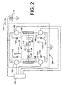
- Figure 2 shows an alternate embodiment for the driver 32 using a pulse width modulation driver 32b including an H-bridge of semiconductor switches 102, 104, 106, and 108 connected to the series resonant circuit 25.
- Arrows 110, 112, 114, 116 show a typical free-wheel current path for times when the switches are all off and the resonant current needs to flow.
- the semiconductor switches include freewheel diodes such as 118, 119, 121, 123 that allow reaction currents to flow automatically. Forward conduction in semiconductor switches 102, 104, 106, 108 is enabled at the appropriate times by signals from the control circuits including circuit 64.
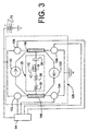
- FIG. 3 shows an alternate embodiment of the pulse width modulated driver incorporating two improved free-wheel paths, 120, 122 which bypass the semiconductor switches 102, 104, 106, and 108 and avoid returning current to the battery 70.
- This technique avoids heating the battery 70.
- Bypassing the battery 70 during the freewheeling portion of the cycle makes the resonant excitation more efficient and reduces the harmonic content of the resulting excitation current waveform 34.
- Each freewheel path 120, 122 allows freewheeling in only one direction.
- the two freewheel paths are connected in opposite polarity with respect to the connection points at the two ends of the series resonant circuit 25, said connection points henceforth being referred to as bus elements 146 and 148.
- Each freewheel path 120, 122 is enabled during the appropriate periods of the conduction cycle by signals from the control system 64.
- Figure 4 illustrates one embodiment of one alternate freewheel path 122 and shows a self-charging, optically-enabled circuit for conducting the freewheeling current during half the resonant cycle in which the field excitation current flows as shown by arrow 112, that is during the half cycle when bus element 146 is nominally connected to the positive terminal of the power supply 70 via switch 108.
- Control signal 130 from controller 64 turns on the opto-transistor 132 by turning on transistor 134, which is regulated by resistors 136 and 138.
- Capacitor 140 provides the energy for the transistor portion of opto-transistor 132.
- Capacitor 140 is automatically charged by the connections of diode 142 and resistor 144 to the bus elements 146 and 148 during the half cycle that bus element 148 is nominally connected to the positive terminal of power supply 70 via switch 102.
- the optical signal caused by the control signal 130 allows conduction through transistor 132, diode 150, and resistor 152. This turns on the semiconductor switch 160 and allows the free-wheel current to pass through the switch 160 and through diode 162 and to continue to circulate through the resonant circuit 25 even when the H-Bridge switches, 102, 104, 106, 108 are all closed.
Landscapes
- Engineering & Computer Science (AREA)
- Power Engineering (AREA)
- Control Of Eletrric Generators (AREA)
- Inverter Devices (AREA)
Claims (11)
- Vorrichtung zum Erzeugen von Netzfrequenz-Wechselstrom aus der Drehung einer Welle (24), wobei die Netzfrequenz-Energieerzeugung unabhängig von der Geschwindigkeit der Welle (24) ist, wobei die Vorrichtung eine Mehrzahl von Ankerpolen mit Magnetpfaden und Ankerspulen (12, 14, 16), wobei jede der Ankerspulen (12, 14, 16) eine individuelle Ausgabe (40, 42, 44) aufweist, einen Läufer (22) mit einem oder mehreren Magnetpfaden (23) und koppelbar mit der Welle (24), so dass die Drehung der Welle (24) eine Veränderung des Magnetflusspegels in den Ankerpolen hervorrufen wird, und eine Feldspule (18) zum Erregen des Magnetpfades des Läufers (22) und der Ankerpole aufweist, dadurch gekennzeichnet, dass:a. die Mehrzahl von lankerpolen verlustarme Ankerpole sind;b. der Läufer (22) ein verlustarmer Läufer ist; undc. die Feldspule (18) einen Teil eines Serienresonanzkreises (25) bildet, welcher aufweist:wobei der Ersatzwiderstand (30), der parasitäre Widerstand (28), die Induktivität der Feldspule (18) und die Resonanzfrequenz so gewählt sind, dass die in der Feldspule (18) gespeicherte Spitzenenergie in jedem Halbzyklus wenigstens zweimal größer als die Energie ist, die in dem parasitären Widerstand während jedes Halbzyklus verloren geht.(i) eine Induktivität der Feldspule (18);(ii) einen Kondensator (26), der gewählt ist, um den Serienresonanzkreis (25) auf eine gewünschte Energie-Frequenz einzustellen;(iii)einen Treiber, um das Resonanzverhalten des Serienresonanzkreises (25) bei der gewünschten Energie-Frequenz zu erregen; und(iv) einen Ersatzwiderstand (30) gleich einem parasitären Widerstand (28) der Feldspule plus einem Verlustwiderstand aus Wirbelströmen und Magnetpfadverlusten, die mit den verlustarmen Ankerpolen und dem verlustarmen Läufer (24) verbunden sind,
- Vorrichtung gemäß Anspruch 1, wobei die Vorrichtung ein Gleichrichtersystem (46), um die einzelnen Ausgaben (40, 42, 44) der Ankerspulen (12, 14, 16) in eine einphasige gleichgerichtete Ausgabe (48) zu leiten, und ein Last-Kommutierungssystem (54) zum Umschalten der Polarität der elektrischen Verbindung zwischen einer Last (68) und der gleichgerichteten Ausgabe (48) aufweist, um eine kommutierte Ausgabe (56) in jedem Halbzyklus bei Nullspannungs-Durchgängen (55) der Ausgabe zu erzeugen.
- Vorrichtung gemäß Anspruch 2, wobei die Vorrichtung ferner eine Rückkopplungs-Steuerschaltung (64) aufweist, die in Funktion ist,(i) um die Erregung der Feldspule (18) zu steuern, so dass die kommutierte Ausgabe und die einphasige gleichgerichtete Ausgabe (48) mit der Phase und der Amplitude eines Referenzsignals übereinstimmen;(ii) um das Last-Kommutierungs-Umschalten des Last-Kommutierungssystems (54) an den Nullspannungs-Durchgängen (55) der Ausgabe zu steuern; und(iii) um den Anschluss der kommutierten Ausgabe (56) und der einphasigen gleichgerichteten Ausgabe (48) an eine externe Last oder ein externes Netz (68) zu steuern, wenn die Phase oder die Amplitude innerhalb des festgelegten Toleranzen ist.
- Vorrichtung gemäß Anspruch 3, wobei die Vorrichtung ferner eine Treiberschaltung (32) aufweist, um sinusförmige Resonanzströme in der Feldspule (18) basierend auf Befehlen von der Rückkopplungs-Steuerschaltung (64) zu erzeugen, wobei die Treiberschaltung (32) ausgelegt ist, ihre eigenen internen Verluste zu minimieren.
- Vorrichtung gemäß irgendeinem vorhergehenden Anspruch,
wobei die Ankerpole Magnetpfade (23) aufweisen, die magnetisches Material mit niedrigen Kernverlusten aufweisen, und der Läufer (22) Magnetpfade (23) aufweist, die magnetisches Material mit niedrigen Kernverlusten aufweisen. - Vorrichtung gemäß Anspruch 5, wobei das magnetische Material mit niedrigen Kernverlusten der Magnetpfade (23) der Ankerpole und des Läufers (22) ein Material mit hoher magnetischer Permeabilität mit niedrigen Kernverlusten ist.
- Vorrichtung gemäß Anspruch 6, wobei das Material aus der Gruppe gewählt ist, die aus lamelliertem Magnetblech und lamelliertem Elektrostahl besteht.
- Vorrichtung gemäß Anspruch 3 oder Anspruch 4, wobei das Gleichrichtersystem (46) eine Mehrzahl von Dioden aufweist, die für eine natürliche Kommutierung sorgen, und wobei das Last-Kommutierungssystem (54) eine Halbleiter-H-Brücke mit Halbleiterschaltern (102, 104, 106, 108) aufweist, die durch die Rückkopplungs-Steuerschaltung (64) wählbar sind.
- Vorrichtung gemäß Anspruch 4, wobei die Treiberschaltung (32) einen Leistungsverstärker aufweist, der eine sinusförmige Spannungsstimulation für den Serienresonanzkreis (25) aufweist und durch Signale von der Rückkopplungs-Steuerschaltung (64) geregelt wird.
- Vorrichtung gemäß Anspruch 9, wobei die Treiberschaltung (32) eine Pulsbreitenmodulationsschaltung (32b) aufweist, die eine H-Brücke aufweist, die den Serienresonanzkreis (25) einschließlich der Feldspule (18) mit einer unipolaren Niederspannungs-Gleichstrom-Energieversorgung (70) verbindet.
- Vorrichtung gemäß Anspruch 3 oder Anspruch 4, wobei das Gleichrichtersystem (46) zwei parallele Sätze von Thyristoren aufweist, die in entgegengesetzter Polarität angeordnet sind, wobei jeder der parallelen Sätze abwechselnd durch Steuersignale von der Rückkopplungs-Steuerschaltung (64) eingeschaltet wird, und wobei jeder der parallelen Sätze angeordnet ist, um, wenn sie eingeschaltet sind, für eine natürliche Kommutierung zu sorgen, und wobei das Last-Kommutierungssystem (54) Mittel zur abwechselnden Auswahl von jedem der parallelen Sätze von Thyristoren aufweist, um die Polarität der Gleichrichtung in Bezug auf die Last (68) umzukehren.
Applications Claiming Priority (3)
| Application Number | Priority Date | Filing Date | Title |
|---|---|---|---|
| US09/002,121 US6051959A (en) | 1997-12-31 | 1997-12-31 | Apparatus for resonant excitation of high frequency alternator field |
| US2121 | 1997-12-31 | ||
| PCT/US1998/027771 WO1999034503A1 (en) | 1997-12-31 | 1998-12-22 | Apparatus for resonant excitation of high frequency alternator field |
Publications (3)
| Publication Number | Publication Date |
|---|---|
| EP1044496A1 EP1044496A1 (de) | 2000-10-18 |
| EP1044496A4 EP1044496A4 (de) | 2003-05-28 |
| EP1044496B1 true EP1044496B1 (de) | 2006-03-29 |
Family
ID=21699324
Family Applications (1)
| Application Number | Title | Priority Date | Filing Date |
|---|---|---|---|
| EP98966112A Expired - Lifetime EP1044496B1 (de) | 1997-12-31 | 1998-12-22 | Vorrichtung zur resonanten erregung eines hochfrequenten generatorfeldes |
Country Status (7)
| Country | Link |
|---|---|
| US (1) | US6051959A (de) |
| EP (1) | EP1044496B1 (de) |
| KR (1) | KR100632805B1 (de) |
| AU (1) | AU2208699A (de) |
| CA (1) | CA2310076C (de) |
| DE (1) | DE69834060T2 (de) |
| WO (1) | WO1999034503A1 (de) |
Families Citing this family (16)
| Publication number | Priority date | Publication date | Assignee | Title |
|---|---|---|---|---|
| US6177746B1 (en) | 1999-10-21 | 2001-01-23 | Christopher N. Tupper | Low inductance electrical machine |
| US6175178B1 (en) | 1999-10-21 | 2001-01-16 | Christopher N. Tupper | Low inductance electrical machine for flywheel energy storage |
| US6570370B2 (en) | 2001-08-21 | 2003-05-27 | Raven Technology, Llc | Apparatus for automatic tuning and control of series resonant circuits |
| US6727621B1 (en) * | 2003-04-22 | 2004-04-27 | Northland/Scott Fetzer Company | Motor-based electrical power supply |
| US7071657B2 (en) * | 2004-03-04 | 2006-07-04 | Raven Technology, Llc | Method and apparatus for the production of power frequency alternating current directly from the output of a single-pole type generator |
| US7802738B2 (en) | 2004-07-16 | 2010-09-28 | Nelson Irrigation Corporation | Power-assisted docking station for mobile irrigation apparatus |
| US7140563B2 (en) | 2004-07-16 | 2006-11-28 | Nelson Irrigation Corporation | Linear-feed irrigation apparatus and related method |
| US8088057B2 (en) * | 2005-02-01 | 2012-01-03 | James David Honeycutt | Apparatus and methods to improve sleep, reduce pain and promote natural healing |
| US7615904B2 (en) | 2007-01-24 | 2009-11-10 | Raven Energy Alternatives, Llc | Brushless high-frequency alternator and excitation method for three-phase AC power-frequency generation |
| US8076814B2 (en) | 2007-01-24 | 2011-12-13 | Raven Energy Alternatives, Llc | Brushless high-frequency alternator and excitation method for DC, single-phase and multi-phase AC power-frequency generation |
| US8167784B1 (en) * | 2007-12-03 | 2012-05-01 | James David Honeycutt | Apparatus and methods to generate circadian rhythm based pulsed electromagnetic fields using micro-watts of electrical energy |
| US9144203B2 (en) | 2009-05-15 | 2015-09-29 | Project 088 Llc | Continuous-feed linear irrigator with separate or integrated docking devices and related method |
| US9020590B1 (en) * | 2010-01-27 | 2015-04-28 | James David Honeycutt | Apparatus to transcutaneously stimulate resonant frequencies of mammals |
| US8773080B2 (en) * | 2010-12-16 | 2014-07-08 | Kohler Co. | Resonant commutation system for exciting a three-phase alternator |
| NO341430B1 (en) * | 2015-01-19 | 2017-11-13 | Waertsilae Norway As | An apparatus and a method for wireless transmission of power between DC voltage sources |
| CN116699568B (zh) * | 2023-07-28 | 2024-01-12 | 中测国检(北京)科技有限责任公司 | 一种基于雪崩二极管的测距频率检测用光电转换装置 |
Family Cites Families (6)
| Publication number | Priority date | Publication date | Assignee | Title |
|---|---|---|---|---|
| US3916284A (en) * | 1974-06-13 | 1975-10-28 | Outdoor Energy Products Inc | Polyphase alternator with single phase output |
| SU921025A1 (ru) * | 1980-05-20 | 1982-04-15 | Научно-исследовательский и экспериментальный институт автомобильного электрооборудования и автоприборов | Устройство дл питани подвижных объектов |
| US4956598A (en) * | 1988-12-16 | 1990-09-11 | Sundstrand Corporation | Low distortion control for a VSCF generating system |
| US4992920A (en) * | 1989-09-13 | 1991-02-12 | Davis Donald E | Regulated AC power system energized by variable speed prime mover |
| EP0454039B1 (de) * | 1990-04-24 | 1996-10-23 | Nippondenso Co., Ltd. | Eine Mehrzahl unabhängiger Dreiphasenwicklungen aufweisender Wechselstromgenerator |
| US5780997A (en) * | 1996-10-03 | 1998-07-14 | Sundstrand Corporation | Variable reluctance alternating current generator |
-
1997
- 1997-12-31 US US09/002,121 patent/US6051959A/en not_active Expired - Lifetime
-
1998
- 1998-12-22 EP EP98966112A patent/EP1044496B1/de not_active Expired - Lifetime
- 1998-12-22 WO PCT/US1998/027771 patent/WO1999034503A1/en not_active Ceased
- 1998-12-22 DE DE69834060T patent/DE69834060T2/de not_active Expired - Lifetime
- 1998-12-22 AU AU22086/99A patent/AU2208699A/en not_active Abandoned
- 1998-12-22 CA CA002310076A patent/CA2310076C/en not_active Expired - Fee Related
- 1998-12-22 KR KR1020007007268A patent/KR100632805B1/ko not_active Expired - Fee Related
Also Published As
| Publication number | Publication date |
|---|---|
| DE69834060D1 (de) | 2006-05-18 |
| WO1999034503A1 (en) | 1999-07-08 |
| KR100632805B1 (ko) | 2006-10-11 |
| KR20010033745A (ko) | 2001-04-25 |
| US6051959A (en) | 2000-04-18 |
| EP1044496A1 (de) | 2000-10-18 |
| EP1044496A4 (de) | 2003-05-28 |
| CA2310076A1 (en) | 1999-07-08 |
| CA2310076C (en) | 2009-10-20 |
| DE69834060T2 (de) | 2006-10-26 |
| AU2208699A (en) | 1999-07-19 |
Similar Documents
| Publication | Publication Date | Title |
|---|---|---|
| US6051959A (en) | Apparatus for resonant excitation of high frequency alternator field | |
| JP4003409B2 (ja) | 多出力電力変換回路 | |
| US6787931B2 (en) | Starter generator for internal combustion engine | |
| US11634039B2 (en) | System and method for integrated battery charging and propulsion in plug-in electric vehicles | |
| KR100440668B1 (ko) | 다상 스위치드 유도성 부하용 변환회로 | |
| US7151359B2 (en) | Variable reluctance generator | |
| US20250055397A1 (en) | Brushless wound field synchronous machines | |
| Anand et al. | Analysis and modeling of different types of converter in switched reluctance motor for reducing the torque ripple | |
| RU2177883C2 (ru) | Способ и электрическая цепь для преобразования электрической энергии | |
| US7071657B2 (en) | Method and apparatus for the production of power frequency alternating current directly from the output of a single-pole type generator | |
| JP4370068B2 (ja) | 特に路上走行車輛用の三相回路網による発電装置 | |
| JPS644439B2 (de) | ||
| RU2579439C2 (ru) | Избирательное управление двигателем переменного тока или двигателем постоянного тока | |
| CZ283862B6 (cs) | Způsob pohánění permanentně buzených elektrických jednofázových strojů na střídavý proud | |
| US6906490B2 (en) | Starting of switched reluctance generators | |
| JP7407247B1 (ja) | バッテリ保護回路 | |
| JP4736155B2 (ja) | インバータ装置 | |
| CN120658144B (zh) | 一种适用于驱动开关磁阻电机的短尾拓扑电路及控制策略 | |
| JPH09275698A (ja) | スイッチド・リラクタンスモータの駆動回路およびその制御方法 | |
| JP2861084B2 (ja) | 可変リラクタンスモータの駆動装置 | |
| Cai et al. | Asymmetric Drive-Based Commutation Control of A Decoupled Multifrequency Multiphase Wireless Power Transfer SRM Drive System | |
| JPS6326637B2 (de) | ||
| JPH0488900A (ja) | 直並列切換回転電機 | |
| JP2000316297A (ja) | 始動発電機 | |
| KR20130055887A (ko) | 권선형 유도 전동기의 전력 회생 장치 |
Legal Events
| Date | Code | Title | Description |
|---|---|---|---|
| PUAI | Public reference made under article 153(3) epc to a published international application that has entered the european phase |
Free format text: ORIGINAL CODE: 0009012 |
|
| 17P | Request for examination filed |
Effective date: 20000606 |
|
| AK | Designated contracting states |
Kind code of ref document: A1 Designated state(s): DE FR GB IT |
|
| RIC1 | Information provided on ipc code assigned before grant |
Ipc: 7H 02P 9/30 B Ipc: 7H 02P 9/44 A |
|
| A4 | Supplementary search report drawn up and despatched |
Effective date: 20030410 |
|
| 17Q | First examination report despatched |
Effective date: 20050401 |
|
| GRAP | Despatch of communication of intention to grant a patent |
Free format text: ORIGINAL CODE: EPIDOSNIGR1 |
|
| GRAS | Grant fee paid |
Free format text: ORIGINAL CODE: EPIDOSNIGR3 |
|
| GRAA | (expected) grant |
Free format text: ORIGINAL CODE: 0009210 |
|
| AK | Designated contracting states |
Kind code of ref document: B1 Designated state(s): DE FR GB IT |
|
| REG | Reference to a national code |
Ref country code: GB Ref legal event code: FG4D |
|
| REF | Corresponds to: |
Ref document number: 69834060 Country of ref document: DE Date of ref document: 20060518 Kind code of ref document: P |
|
| ET | Fr: translation filed | ||
| PLBE | No opposition filed within time limit |
Free format text: ORIGINAL CODE: 0009261 |
|
| STAA | Information on the status of an ep patent application or granted ep patent |
Free format text: STATUS: NO OPPOSITION FILED WITHIN TIME LIMIT |
|
| 26N | No opposition filed |
Effective date: 20070102 |
|
| PGFP | Annual fee paid to national office [announced via postgrant information from national office to epo] |
Ref country code: GB Payment date: 20141219 Year of fee payment: 17 |
|
| PGFP | Annual fee paid to national office [announced via postgrant information from national office to epo] |
Ref country code: FR Payment date: 20141219 Year of fee payment: 17 |
|
| PGFP | Annual fee paid to national office [announced via postgrant information from national office to epo] |
Ref country code: DE Payment date: 20141222 Year of fee payment: 17 Ref country code: IT Payment date: 20141223 Year of fee payment: 17 |
|
| REG | Reference to a national code |
Ref country code: DE Ref legal event code: R119 Ref document number: 69834060 Country of ref document: DE |
|
| GBPC | Gb: european patent ceased through non-payment of renewal fee |
Effective date: 20151222 |
|
| REG | Reference to a national code |
Ref country code: FR Ref legal event code: ST Effective date: 20160831 |
|
| PG25 | Lapsed in a contracting state [announced via postgrant information from national office to epo] |
Ref country code: DE Free format text: LAPSE BECAUSE OF NON-PAYMENT OF DUE FEES Effective date: 20160701 Ref country code: GB Free format text: LAPSE BECAUSE OF NON-PAYMENT OF DUE FEES Effective date: 20151222 |
|
| PG25 | Lapsed in a contracting state [announced via postgrant information from national office to epo] |
Ref country code: FR Free format text: LAPSE BECAUSE OF NON-PAYMENT OF DUE FEES Effective date: 20151231 |
|
| PG25 | Lapsed in a contracting state [announced via postgrant information from national office to epo] |
Ref country code: IT Free format text: LAPSE BECAUSE OF NON-PAYMENT OF DUE FEES Effective date: 20151222 |