EP1044495B1 - A driving control system for electric motors - Google Patents
A driving control system for electric motors Download PDFInfo
- Publication number
- EP1044495B1 EP1044495B1 EP98960948A EP98960948A EP1044495B1 EP 1044495 B1 EP1044495 B1 EP 1044495B1 EP 98960948 A EP98960948 A EP 98960948A EP 98960948 A EP98960948 A EP 98960948A EP 1044495 B1 EP1044495 B1 EP 1044495B1
- Authority
- EP
- European Patent Office
- Prior art keywords
- voltage
- commutation
- power source
- coils
- control system
- Prior art date
- Legal status (The legal status is an assumption and is not a legal conclusion. Google has not performed a legal analysis and makes no representation as to the accuracy of the status listed.)
- Expired - Lifetime
Links
Images


Classifications
-
- H—ELECTRICITY
- H02—GENERATION; CONVERSION OR DISTRIBUTION OF ELECTRIC POWER
- H02P—CONTROL OR REGULATION OF ELECTRIC MOTORS, ELECTRIC GENERATORS OR DYNAMO-ELECTRIC CONVERTERS; CONTROLLING TRANSFORMERS, REACTORS OR CHOKE COILS
- H02P6/00—Arrangements for controlling synchronous motors or other dynamo-electric motors using electronic commutation dependent on the rotor position; Electronic commutators therefor
- H02P6/14—Electronic commutators
- H02P6/16—Circuit arrangements for detecting position
-
- H—ELECTRICITY
- H02—GENERATION; CONVERSION OR DISTRIBUTION OF ELECTRIC POWER
- H02P—CONTROL OR REGULATION OF ELECTRIC MOTORS, ELECTRIC GENERATORS OR DYNAMO-ELECTRIC CONVERTERS; CONTROLLING TRANSFORMERS, REACTORS OR CHOKE COILS
- H02P6/00—Arrangements for controlling synchronous motors or other dynamo-electric motors using electronic commutation dependent on the rotor position; Electronic commutators therefor
- H02P6/08—Arrangements for controlling the speed or torque of a single motor
- H02P6/085—Arrangements for controlling the speed or torque of a single motor in a bridge configuration
Definitions
- the present invention refers to a driving control system for an electric motor, particularly a three-phase motor with permanent magnets, of the type used in refrigeration compressors and in which a control unit commands the adequate energization to the motor, as a function of the information received from a position sensor of this system operatively connected to the motor.
- Such motors consist of a stator containing coils, a rotor with permanent magnets, an inverter applying current to the stator coils, a position sensor, which informs on the time and period each coil assembly has to remain energized, and a central control, which processes the information on the current, rotor speed and rotor position and sends command signals to the inverter.
- Three-phase motors with permanent magnets of the type used in compressors of refrigeration systems are electronically actuated and usually use inverters with three commutation arms.
- each motor phase is connected between two commutation switches of a respective commutation arm of the inverter, the three arms forming this inverter being connected to the same power source through a rectifying diode bridge connected to a ripple filter capacitor.
- the torque control may be usually effected in two ways: by current hysteresis or by controlling the voltage applied to the motor.
- a median current is applied to the motor phases selected by a controller to be actuated.
- This current is controlled by a comparator with hysteresis which, when the current reaches a maximum value, turns off the selected switches, turning the latter on when the current reaches a minimum value and thus generating a voltage modulation signal (PWM), also called switching frequency (which is much higher than the rotation of the motor) and which maintains the current around a reference value, which is adjusted to maintain a constant speed.
- PWM also called switching frequency (which is much higher than the rotation of the motor) and which maintains the current around a reference value, which is adjusted to maintain a constant speed.
- the voltage modulation signal (PWM) which is generated by the comparator, may vary its switching frequency and its switch conduction period ("duty cycle", ratio between the closed switch period and full switching period) at each time. This type of control reacts more rapidly to load disturbs, but is more complex to be implemented in microcontrolled systems, since it needs at least one A/D converter and a powerful micro
- a voltage value is applied to the motor phases which have been selected by the controller to be actuated.
- This voltage is modulated by the voltage modulation signal (PWM), also known as switching frequency, which is generated by a timer and whose average value is adjusted by the control unit, in order to maintain the desired speed.
- PWM voltage modulation signal
- This voltage adjustment is achieved by switching (on and off) the switches selected by the control unit during the period in which the motor phase is fed with voltage from a power source.
- the switch conduction period ratio between the closed switch period and full switching period
- the voltage modulation signal usually has a fixed switching frequency and a switch conduction period, which is adjusted at each turn. This type of control does not react rapidly to sudden load disturbs and is indicated to applications in which the load does not vary suddenly, such as in refrigeration systems. However, it is a simpler control to be implemented in microcontrolled systems.
- US-A-5 406 185 discloses a two-phase inverter for a three-phase delta-connected motor.
- a driving control system for an electric star-connected motor with N coils including: a power source in direct current; an inverter having commutation arms with the opposite ends connected to the power source, each including switch means, each commutation arm being medianly connected to a respective coil; a position sensor means connected to the coils; and a control unit, operatively connected to the position sensor means and to the switch means, in order to operate the latter as a function of the signals received from the position sensor means.
- the inverter has N-1 commutation arms and the power source has, between positive and negative terminals of equal voltage, a median terminal, of null voltage, to which is directly connected a first coil, the inverter having a first switching condition of the switch means, in which the first coil is subjected to a null voltage, while two other coils are subjected to a determined voltage value, and a second switching condition of the switch means, in which the first coil and any of said other coils are subjected to a voltage value equivalent to half the determined voltage value and corresponding to the nominal voltage, the control unit determining to the switch means, the latter being in one of the first and second switching conditions, a switching frequency and a switch conduction period, which are defined so that the voltage value which is effectively applied to the coils is that one corresponding to the speed and torque required to the electric motor, independently from the switching condition of the switch means.
- an electric motor 10 which is a three-phase motor having a rotor with permanent magnets, is operatively connected to a power source 20, in direct current, through an inverter 30 supplying electric current and voltage to one of three coils 11, 12 and 13 of the electric motor 10, by selective instruction from a control unit 40, which is operatively connected to the inverter 30 and to a position sensor means 50.
- the inverter 30 is provided with commutation arms 31, 32 and 33, each including switch means in the form of a first and a second commutation switch 31a and 31b, 32a and 32b, 33a and 33b, and having opposite ends connected to the power source 20, the switching of said switch means being commanded by the control unit 40, as a function of the signals received from the position sensor means 50.
- Each first commutation switch 31a, 32a and 33a has a respective terminal, connectable to a positive terminal 21 of the power source 20, each of the second commutation switches 31b, 32b and 33b having a terminal connected to a negative terminal 22 of the power source 20.
- each first and second commutation switch of each commutation arm 31, 32 and 33 of the inverter 30 is connected, respectively and electrically, a terminal of one of the coils, 11, 12 and 13 of the electric motor 10, so that, at each closing of a first commutation switch 31a, 32a and 33a of the inverter 30, a corresponding coil 11, 12 and 13 of the electric motor 10 is electrically connected to a positive terminal of the power source 20 and, analogically, at each closing of a second commutation switch 31b, 32b and 33b of the inverter 30, a corresponding coil 11, 12 and 13 of the electric motor 10 is electrically connected to a negative terminal of the power source 20.
- the power source 20 comprises a ripple filter capacitor 23 and a rectifying diode bridge 24, having a pair of terminals connected to a conventional alternated current source Vac.
- the power source 20 has its positive and negative poles respectively and selectively connected to the first and second commutation switches 31a, 31b, 32a, 32b and 33a, 33b of each commutation arm 31, 32 and 33, in order to supply the electric motor 10 with a continuous voltage Edc.
- the position sensor means 50 which forms the driving system of the electric motor in question detects the voltages induced to each of the three coils 11, 12 and 13 of the motor and sends this information to the control unit 40 which, as a function of said information, of the average current and voltage values and of a reference speed value, sends command signals to the inverter 30 so that, through the latter, each two coils 11, 12 and 13 of the electric motor 10 may be sequentially energized in a determined instant and by a determined time interval defined as a function of the speed and load (torque) of the motor.
- the energization of the coils occurs in pairs.
- each of the 6 commutation switches of the inverter 30 is switched and maintained in a switching condition during a time corresponding to 120° of the electric cycle of the motor (figures 4 and 4a), said switching being instructed by the control unit 40, so that the period in which a first commutation switch of one of the commutation arms is switched corresponds to half the period in which two other second commutation switches are switched, each switch belonging to one of the other two commutation arms, thus determining that, in the period in which each of the commutation switches is switched, one of the coils of the electric motor 10 be fed through the positive terminal of the power source 20, during a time interval corresponding to 120° of the electric cycle of the motor, while in this time interval the other coils are sequentially and temporarily fed through the negative terminal of the power source 20.
- the first coil 11 of the electric motor 10 will be fed with a certain positive voltage from the power source 20 (Edc/2). While this first commutation switch 31a is being switched (during 120° of the electric cycle of the motor), one of the second commutation switches 32b and 33b, for instance the second commutation switch 32b, will remain switched during a time interval corresponding to 60° of the electric cycle of the motor, from the beginning of the switching of the first commutation switch 31a, allowing the coil 12 of the electric motor 10 to receive a certain negative voltage from the power source 20 (-Edc/2). During this time interval, voltage is fed to the motor circuit, corresponding to Edc, between the positive and negative terminals of the power source.
- the first and second switches 33a and 33b of the commutation arm 33 connected to the coil 13 remain open during this time interval and consequently this coil is not fed with voltage from the power source 20.
- the control unit 40 instructs the opening of the second commutation switch 32b and the instantenous start of the switching of the second commutation switch 33b, disconnecting the coil 12 of the electric motor 10 from the power source 20 and allowing the coil 13 to be fed with the certain negative voltage (-Ecd/2) from the power source 20.
- the control unit 40 instructs the opening of said switch and the switching of the first commutation switch 32a, allowing the coil 12 to be fed with the certain positive voltage Edc/2 from the power source 20.
- the second commutation switches 33b and 31b will be each sequentially switched by time intervals corresponding to 60° of the motor turn.
- each coil 11, 12 and 13 of the electric motor 10 has a graphic behavior, such as illustrated in figure 4, having a switching period Tch during 2/3 of the time interval (or of the electric cycle of the motor) of operation in said voltage of the power source 20 and during which said coils are subjected, during a time interval in which the respective commutation switch is closed (Ton), to a voltage value Edc (positive or negative) equal to that of the power source 20, intercalated with time intervals in which the voltage is null (Toff).
- the control unit 40 instructs the first and second commutation switches, which have to be switched by 120°, to continuously and instantenously alternate said switching, so that the effective switching voltage applied to the coils associated with these commutation switches is that corresponding to the speed and torque required for the motor.
- This switching frequency (1/Tch) is fixed and defined in the project phase, while the switch conduction period (Ton/Tch) within the switching frequency is adjusted as a function of the requirement for altering the operational speed and torque of the electric motor 10.
- the switch conduction period is defined by the ratio between the time period in which each first and second commutation switch remains connected to the power source 20 and the full switching time, said conduction period being constant during this switching period. This relation is only altered after each electric cycle of the motor has been completed, preventing speed alterations required during each motor turn from being effected.
- the inverter 30 is constructed in order to have a first and a second closing condition of its switch means, for each of said switches the control unit 40 determining a conduction period within the switching frequency, as a function of the requirement for speed and torque of the electric motor 10, each conduction period of the switching frequency defining a determined voltage to be applied to the coils (phases) electrically connected to a power source 20, constructed to operate with the inverter 30 of the present invention.
- the poswer source 20 of the present invention has, between the positive terminal 21 and the negative terminal 22 with the same voltage 2Edc, a median terminal 25, of null voltage, to which is directly connected a first pair of coils 11.
- the power source 20 comprises a pair of capacitors 26, ripple capacitors with the same value Edc, disposed in series between the positive 21 and negative 22 terminals thereof, a median terminal 25 being defined therebetween.
- the power source 20 further includes voltage rectifying means having a pair of terminals connected to a conventional alternated current source Vac, so that to supply the motor 10, through inverter 30, with different voltage values: 0, +Edc,-Edc, +2Edc, -2Edc, as described below.
- the inverter 30 comprises N-1 commutation arms, each being medianly connected, between the respective switch means thereof, with a corresponding coil of the electric motor 10.
- the inverter 30 thus constructed has a first and second switching condition of the switch means of its N-1 commutation arms. In the first switching condition, each two coils, other than the first coil 11, are subjected to a determined voltage value (2Edc), while the first coil 11 and the other coils not connected to the power source 20, are subjected to a null voltage.
- either of the N-1 coils and also the first coil are subjected to a voltage value equivalent to half the determined voltage value (Edc) corresponding to the nominal operational voltage of the motor, while the other coils are subjected to a null voltage.
- the control unit 40 further determines that, as a function of occuring the first swiching condition, there is a reduction in the switch conduction period by a value which results in the coils being energized with the nominal voltage.
- the inverter 30 has two commutation arms 32, 33, each provided with a pair of commutation switches comprising a first and a second commutation switch 32a, 32b, 33a, 33b.
- a first commutation switch of one of the the commutation arms is connected to the positive terminal 21 of the power source, while a second commutation switch of another commutation arm is simultaneously connected to the negative terminal 22 of the power source 20.
- the coils connected to these commutation arms are submitted to a voltage value of 2Edc, each of said coils being individually submitted to a voltage value whose module is equal to Edc, while the first coil is submitted to a null voltage value.
- any one of the first and second commutation switches of one of the commutation arms is individually connected to one of the positive 21 and negative 22 terminals of the power source 20, so that the coils of one motor phase and the coils of the first phase are submitted to a voltage value corresponding to Edc.
- each of the coils of one motor phase is individually submitted to a voltage value with a module equal to Edc/2.
- a corresponding coil 12, 13 of the electric motor 10 is electrically connected to the positive terminal 21 of the power source 20, in order to be fed by the latter through the first coil 11 with a voltage value Edc on the coils, during a time interval corresponding to a rotation of 60° of the electric motor 10.
- each respective coil 12, 13 and the first coil 11 of the electric motor 10 are individually supplied with a continuous voltage Edc/2 e -Edc/2, respectively.
- the supply of the first coil 11 will depend on the supply of one of the first and second commutation switches of one of the commutation arms 31, 32 of the inverter 30.
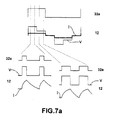
- each of the four commutation switches 32a, 32b, 33a and 33b of the inverter 30 is switched and maintained in a switching condition, during a time corresponding to 120° of the electric cycle of the motor (figures 7 and 7a), said switching being instructed by the control unit 40, so that the period in which one of the first commutation switches 32a, 33a of one of the commutation arms 32, 33 is switched corresponds to half the period in which the second commutation switch of the other commutation arm is switched, thus determining that one of the coils 12 an 13 of the electric motor 10 be fed through one of the positive 21 and negative 22 terminals of the power source 20, during a time interval corresponding to 60° of the electric cycle of the motor, while, in said time interval, the first coil 11 remains temporarily subjected to a null voltage value.
- the coil 12 connected to this commutation arm 32 is being fed by the positive terminal 21 of the power source 20. While this first commutation switch 32a is being switched (during 120° of the electric cycle of the motor), the second commutation switch 33b will remain switched during a time interval corresponding to 60° of the motor rotation, from the closing of the first commutation switch 32a, allowing the pair of coils 13 connected to this third commutation arm 33 to receive a negative voltage from the power source 20. In this period, the electric motor 10 is fed with a voltage of 2Edc (first operational condition).
- the control unit 40 instructs the opening of the second commutation switch 32b. This disconnection leads the coil 12 to a feeding condition of Edc/2 and the first coil 11 to a feeding condition of -Edc/2 by the power source 20.
- the control unit 40 instructs the opening of said switch and the switching of the third commutation switch 33a, during a time interval of 120° of the electric cycle of the motor, allowing the respective coil 13 to be fed with positive voltage from the power source 20, through the first coil 11, in the first 60° of the electric cycle of the motor, with the electric motor 10 being supplied with Edc.
- the second commutation switch 32b will be switched during a time interval corresponding to 60° of the electric cycle of the motor.
- this fact does not occur now in the first 60° of the 120° of the electric cycle of the motor in which the switch 33a is switched, but in the final 60° of this cycle (repeating the first operational condition).
- each coil 12, 13 of the electric motor 10 has a graphic behavior as illustrated in figures 7 and 7a, with an operational period submitted to a voltage value (positive or negative) equal to Edc, intercalated, in a staggered manner, with periods of Edc/2 and null voltages, each time period with a determined voltage having a duration corresponding to 60° of the electric cycle of the electric motor 10.
- the driving of the electric motor 10 requires detecting the position of said motor, in order that the control unit 40 determines which coil or coils of the electric motor 10 will be switched at each time.
- the torque control can be made by current hysteresis or by controlling the voltage applied to the motor.
- the implementation of the control system is simplified, since it requires the current to be applied only to the two coils of the electric motor 10 which are connected to the two commutation arms of the inverter 30.
- the voltage which is applied is modulated by a modulating signal (PWM) generated by a timer, the average value thereof being adjusted by the control unit 40 to maintain a constant speed.
- PWM modulating signal
- the control unit 40 will instruct to increase the voltage.
- the control unit 40 will instruct to reduce the voltage applied to the motor.
- This voltage variation is adjusted by modifying the value of the switch conduction period, since an increase or a reduction of said value will mean, respectively, an increase of the voltage value and a reduction of said voltage value in the electric motor 10.
- the present invention makes possible to alter the switch conduction period, with instruction of the control unit 40, be altered, having its value reduced to half, when the peak voltage value in the electric motor 10 reaches a value 2Edc, returning said switch conduction period to its value determined as normal, when the peak voltage value in the motor is reduced to half, i.e., is equal to Edc.
- Edc the average voltage value
- control unit 40 should instruct to reduce the value of the switch conduction period to half, for each electric cycle of the electric motor 10, during the time intervals corresponding to the following angular intervals of said electric circuit: 0° to 60° and 180° to 240° (first operational condition), returning the value of the switch conduction period to its normal value during the time intervals corresponding to the following angular intervals: 60° to 180° and 240° and 240° to 360° (second closing condition).
- control unit 40 may further determine, in these conditions, to occur an increase in the switching frequency of the electric motor 10.
Applications Claiming Priority (3)
| Application Number | Priority Date | Filing Date | Title |
|---|---|---|---|
| BR9706175-1A BR9706175A (pt) | 1997-12-12 | 1997-12-12 | Sistema para controle de acionamento de motor elétrico. |
| BR9706175 | 1997-12-12 | ||
| PCT/BR1998/000107 WO1999031794A2 (en) | 1997-12-12 | 1998-11-27 | A driving control system for electric motors |
Publications (3)
| Publication Number | Publication Date |
|---|---|
| EP1044495A2 EP1044495A2 (en) | 2000-10-18 |
| EP1044495B1 true EP1044495B1 (en) | 2002-02-13 |
| EP1044495A3 EP1044495A3 (en) | 2002-09-11 |
Family
ID=4068630
Family Applications (1)
| Application Number | Title | Priority Date | Filing Date |
|---|---|---|---|
| EP98960948A Expired - Lifetime EP1044495B1 (en) | 1997-12-12 | 1998-11-27 | A driving control system for electric motors |
Country Status (12)
| Country | Link |
|---|---|
| US (1) | US6346785B1 (tr) |
| EP (1) | EP1044495B1 (tr) |
| JP (1) | JP2002509418A (tr) |
| KR (1) | KR100586456B1 (tr) |
| AR (1) | AR017843A1 (tr) |
| AT (1) | ATE213366T1 (tr) |
| BR (1) | BR9706175A (tr) |
| DE (1) | DE69803885T2 (tr) |
| ES (1) | ES2173654T3 (tr) |
| SK (1) | SK5182000A3 (tr) |
| TR (1) | TR200000202T2 (tr) |
| WO (1) | WO1999031794A2 (tr) |
Families Citing this family (9)
| Publication number | Priority date | Publication date | Assignee | Title |
|---|---|---|---|---|
| US20040145324A1 (en) * | 2003-01-28 | 2004-07-29 | Ross Christian E. | Integrated control device for environmental systems |
| JP2005261135A (ja) * | 2004-03-12 | 2005-09-22 | Seiko Epson Corp | モータ及びその駆動制御システム |
| KR20080103846A (ko) * | 2007-05-25 | 2008-11-28 | 엘지전자 주식회사 | 모터의 운전제어장치 및 방법 |
| US8242735B2 (en) * | 2008-07-09 | 2012-08-14 | Caterpillar Inc. | Method and system for temperature-based power converter control |
| DE102010030239A1 (de) | 2010-06-17 | 2011-12-22 | BSH Bosch und Siemens Hausgeräte GmbH | Verfahren und Vorrichtung zum Anlassen eines Elektromotors |
| DE102010030240A1 (de) | 2010-06-17 | 2011-12-22 | BSH Bosch und Siemens Hausgeräte GmbH | Verfahren und Vorrichtung zur Anpassung eines Drehzahlbereichs eines Eletromotors |
| JP2012100514A (ja) * | 2010-10-04 | 2012-05-24 | Asmo Co Ltd | 回転電機の電機子及びその製造方法 |
| KR101470966B1 (ko) * | 2014-01-08 | 2014-12-09 | 연세대학교 산학협력단 | 배터리-파워 rfid 태그의 배터리 전압 공급 회로, 이를 포함하는 배터리-파워 rfid 태그, 배터리 모듈, rfid 태그 칩 모듈 및 배터리-파워 rfid 태그 시스템 |
| CN108173475B (zh) * | 2018-02-11 | 2020-06-02 | 矽力杰半导体技术(杭州)有限公司 | 电机驱动装置和电机 |
Family Cites Families (9)
| Publication number | Priority date | Publication date | Assignee | Title |
|---|---|---|---|---|
| US3764855A (en) * | 1971-02-25 | 1973-10-09 | R Beachley | Zero-ground fault-cutout desensitizing device |
| GB1596681A (en) * | 1977-01-19 | 1981-08-26 | Sony Corp | Drive circuits with speed control for brushless dc motors |
| US4152640A (en) * | 1977-09-23 | 1979-05-01 | Westinghouse Electric Corp. | Two phase high voltage insulation testing of multiphase windings |
| US4135235A (en) | 1977-10-31 | 1979-01-16 | Exxon Research & Engineering Co. | Synthesizer circuit for generating three-tier waveforms |
| DE2804561A1 (de) * | 1978-02-03 | 1979-08-09 | Papst Motoren Kg | Zweipulsiger kollektorloser gleichstrommotor |
| JP2501012B2 (ja) * | 1992-12-17 | 1996-05-29 | インターナショナル・ビジネス・マシーンズ・コーポレイション | 電流測定装置 |
| AU5503194A (en) * | 1993-02-22 | 1994-08-25 | General Electric Company | Single phase electronically commutated motor system and method |
| BR9301879A (pt) * | 1993-05-31 | 1994-12-13 | Brasil Compressores Sa | Sistema e método de acionamento de motores de múltiplas velocidades comutados eletronicamente |
| US5406185A (en) * | 1993-06-04 | 1995-04-11 | Strunk; Timothy L. | Two-phase inverter drive for a three-phase motor |
-
1997
- 1997-12-12 BR BR9706175-1A patent/BR9706175A/pt not_active Application Discontinuation
-
1998
- 1998-11-27 JP JP2000539574A patent/JP2002509418A/ja not_active Ceased
- 1998-11-27 AT AT98960948T patent/ATE213366T1/de not_active IP Right Cessation
- 1998-11-27 TR TR2000/00202T patent/TR200000202T2/tr unknown
- 1998-11-27 ES ES98960948T patent/ES2173654T3/es not_active Expired - Lifetime
- 1998-11-27 EP EP98960948A patent/EP1044495B1/en not_active Expired - Lifetime
- 1998-11-27 WO PCT/BR1998/000107 patent/WO1999031794A2/en active IP Right Grant
- 1998-11-27 KR KR1020007005122A patent/KR100586456B1/ko not_active IP Right Cessation
- 1998-11-27 DE DE69803885T patent/DE69803885T2/de not_active Expired - Fee Related
- 1998-11-27 US US09/462,852 patent/US6346785B1/en not_active Expired - Fee Related
- 1998-11-27 SK SK518-2000A patent/SK5182000A3/sk unknown
- 1998-12-11 AR ARP980106291A patent/AR017843A1/es active IP Right Grant
Also Published As
| Publication number | Publication date |
|---|---|
| ATE213366T1 (de) | 2002-02-15 |
| WO1999031794A3 (en) | 2000-08-24 |
| JP2002509418A (ja) | 2002-03-26 |
| DE69803885T2 (de) | 2002-11-21 |
| EP1044495A2 (en) | 2000-10-18 |
| TR200000202T2 (tr) | 2000-05-22 |
| EP1044495A3 (en) | 2002-09-11 |
| ES2173654T3 (es) | 2002-10-16 |
| WO1999031794A2 (en) | 1999-06-24 |
| BR9706175A (pt) | 1999-09-21 |
| KR100586456B1 (ko) | 2006-06-08 |
| AR017843A1 (es) | 2001-10-24 |
| SK5182000A3 (en) | 2000-10-09 |
| KR20010032010A (ko) | 2001-04-16 |
| US6346785B1 (en) | 2002-02-12 |
| DE69803885D1 (de) | 2002-03-21 |
Similar Documents
| Publication | Publication Date | Title |
|---|---|---|
| US5838127A (en) | Single phase motor for laundering apparatus | |
| US5929590A (en) | Method and apparatus for implementing sensorless control of a switched reluctance machine | |
| US5214371A (en) | Voltage regulator for variable speed permanent magnet alternators | |
| US5825597A (en) | System and method for detection and control of circulating currents in a motor | |
| US20010048278A1 (en) | Cross coupled motor gate drive | |
| US5510696A (en) | Zero current switching between winding sets in a permanent magnet alternator having a split winding stator | |
| JP2004080931A (ja) | 内燃機関用スタータジェネレータ | |
| US6870337B2 (en) | Methods and apparatus for maintaining synchronization of a polyphase motor during power interruptions | |
| JPH04275091A (ja) | 無整流子電動機の駆動制御装置 | |
| EP1044495B1 (en) | A driving control system for electric motors | |
| EP1067670B1 (en) | Controlling method for switched reluctance motor method and motor having a low peak current | |
| US5510688A (en) | Driving system and method for electronically commutated multi-speed motors | |
| KR19980033924A (ko) | 스윗스드 릴럭턴스 모터의 속도제어장치 | |
| US6333610B1 (en) | Speed control device for an electronically commutated multiphase electric motor | |
| US6838842B2 (en) | Method for operating a brushless direct current motor | |
| US7276882B2 (en) | Regulator control circuit and method | |
| JP4736155B2 (ja) | インバータ装置 | |
| JPH06141587A (ja) | ブラシレスモータ駆動装置 | |
| JPH06327286A (ja) | 電動機駆動装置 | |
| US20020145397A1 (en) | Electronically commutated electric motor | |
| KR100259019B1 (ko) | 센서레스 비엘디씨(bldc)모터 구동 제어 방법. | |
| US20040190316A1 (en) | Regulator control circuit and method | |
| JP4465762B2 (ja) | インバータ装置 | |
| KR20010003860A (ko) | 모터의 구동방법 | |
| KR19990081161A (ko) | 모터의 구동방법 |
Legal Events
| Date | Code | Title | Description |
|---|---|---|---|
| PUAI | Public reference made under article 153(3) epc to a published international application that has entered the european phase |
Free format text: ORIGINAL CODE: 0009012 |
|
| 17P | Request for examination filed |
Effective date: 20000125 |
|
| AK | Designated contracting states |
Kind code of ref document: A2 Designated state(s): AT DE ES FR GB IE IT |
|
| GRAG | Despatch of communication of intention to grant |
Free format text: ORIGINAL CODE: EPIDOS AGRA |
|
| 17Q | First examination report despatched |
Effective date: 20010301 |
|
| GRAG | Despatch of communication of intention to grant |
Free format text: ORIGINAL CODE: EPIDOS AGRA |
|
| GRAH | Despatch of communication of intention to grant a patent |
Free format text: ORIGINAL CODE: EPIDOS IGRA |
|
| GRAH | Despatch of communication of intention to grant a patent |
Free format text: ORIGINAL CODE: EPIDOS IGRA |
|
| GRAA | (expected) grant |
Free format text: ORIGINAL CODE: 0009210 |
|
| REG | Reference to a national code |
Ref country code: GB Ref legal event code: IF02 |
|
| AK | Designated contracting states |
Kind code of ref document: B1 Designated state(s): AT DE ES FR GB IE IT |
|
| REF | Corresponds to: |
Ref document number: 213366 Country of ref document: AT Date of ref document: 20020215 Kind code of ref document: T |
|
| REF | Corresponds to: |
Ref document number: 69803885 Country of ref document: DE Date of ref document: 20020321 |
|
| ET | Fr: translation filed | ||
| PUAK | Availability of information related to the publication of the international search report |
Free format text: ORIGINAL CODE: 0009015 |
|
| AK | Designated contracting states |
Kind code of ref document: A3 Designated state(s): AT DE ES FR GB IE IT |
|
| REG | Reference to a national code |
Ref country code: ES Ref legal event code: FG2A Ref document number: 2173654 Country of ref document: ES Kind code of ref document: T3 |
|
| PLBE | No opposition filed within time limit |
Free format text: ORIGINAL CODE: 0009261 |
|
| STAA | Information on the status of an ep patent application or granted ep patent |
Free format text: STATUS: NO OPPOSITION FILED WITHIN TIME LIMIT |
|
| 26N | No opposition filed |
Effective date: 20021114 |
|
| PGFP | Annual fee paid to national office [announced via postgrant information from national office to epo] |
Ref country code: GB Payment date: 20061115 Year of fee payment: 9 |
|
| PGFP | Annual fee paid to national office [announced via postgrant information from national office to epo] |
Ref country code: IE Payment date: 20061123 Year of fee payment: 9 |
|
| PGFP | Annual fee paid to national office [announced via postgrant information from national office to epo] |
Ref country code: IT Payment date: 20061130 Year of fee payment: 9 Ref country code: FR Payment date: 20061130 Year of fee payment: 9 Ref country code: ES Payment date: 20061130 Year of fee payment: 9 Ref country code: AT Payment date: 20061130 Year of fee payment: 9 |
|
| PGFP | Annual fee paid to national office [announced via postgrant information from national office to epo] |
Ref country code: DE Payment date: 20061218 Year of fee payment: 9 |
|
| GBPC | Gb: european patent ceased through non-payment of renewal fee |
Effective date: 20071127 |
|
| REG | Reference to a national code |
Ref country code: IE Ref legal event code: MM4A |
|
| PG25 | Lapsed in a contracting state [announced via postgrant information from national office to epo] |
Ref country code: AT Free format text: LAPSE BECAUSE OF NON-PAYMENT OF DUE FEES Effective date: 20071127 |
|
| PG25 | Lapsed in a contracting state [announced via postgrant information from national office to epo] |
Ref country code: IE Free format text: LAPSE BECAUSE OF NON-PAYMENT OF DUE FEES Effective date: 20071127 Ref country code: DE Free format text: LAPSE BECAUSE OF NON-PAYMENT OF DUE FEES Effective date: 20080603 |
|
| REG | Reference to a national code |
Ref country code: FR Ref legal event code: ST Effective date: 20080930 |
|
| PG25 | Lapsed in a contracting state [announced via postgrant information from national office to epo] |
Ref country code: GB Free format text: LAPSE BECAUSE OF NON-PAYMENT OF DUE FEES Effective date: 20071127 |
|
| REG | Reference to a national code |
Ref country code: ES Ref legal event code: FD2A Effective date: 20071128 |
|
| PG25 | Lapsed in a contracting state [announced via postgrant information from national office to epo] |
Ref country code: FR Free format text: LAPSE BECAUSE OF NON-PAYMENT OF DUE FEES Effective date: 20071130 Ref country code: ES Free format text: LAPSE BECAUSE OF NON-PAYMENT OF DUE FEES Effective date: 20071128 |
|
| PG25 | Lapsed in a contracting state [announced via postgrant information from national office to epo] |
Ref country code: IT Free format text: LAPSE BECAUSE OF NON-PAYMENT OF DUE FEES Effective date: 20071127 |