EP1043575A2 - Baugruppe zur Erzeugung eines optisch wirksamen Spaltes - Google Patents
Baugruppe zur Erzeugung eines optisch wirksamen Spaltes Download PDFInfo
- Publication number
- EP1043575A2 EP1043575A2 EP00101046A EP00101046A EP1043575A2 EP 1043575 A2 EP1043575 A2 EP 1043575A2 EP 00101046 A EP00101046 A EP 00101046A EP 00101046 A EP00101046 A EP 00101046A EP 1043575 A2 EP1043575 A2 EP 1043575A2
- Authority
- EP
- European Patent Office
- Prior art keywords
- guideways
- guide rail
- gap
- assembly according
- slides
- Prior art date
- Legal status (The legal status is an assumption and is not a legal conclusion. Google has not performed a legal analysis and makes no representation as to the accuracy of the status listed.)
- Withdrawn
Links
- 230000003287 optical effect Effects 0.000 title description 6
- 238000006073 displacement reaction Methods 0.000 claims abstract description 12
- 238000005096 rolling process Methods 0.000 claims description 7
- 238000005452 bending Methods 0.000 claims description 3
- 239000000463 material Substances 0.000 claims description 3
- 230000036316 preload Effects 0.000 claims description 3
- 230000006835 compression Effects 0.000 claims description 2
- 238000007906 compression Methods 0.000 claims description 2
- 230000000694 effects Effects 0.000 description 3
- 230000000712 assembly Effects 0.000 description 2
- 238000000429 assembly Methods 0.000 description 2
- 229910000831 Steel Inorganic materials 0.000 description 1
- 230000002411 adverse Effects 0.000 description 1
- 239000011248 coating agent Substances 0.000 description 1
- 238000000576 coating method Methods 0.000 description 1
- 230000001143 conditioned effect Effects 0.000 description 1
- 238000010276 construction Methods 0.000 description 1
- 238000003745 diagnosis Methods 0.000 description 1
- 238000005286 illumination Methods 0.000 description 1
- 239000010959 steel Substances 0.000 description 1
- 239000000725 suspension Substances 0.000 description 1
Images

Classifications
-
- A—HUMAN NECESSITIES
- A61—MEDICAL OR VETERINARY SCIENCE; HYGIENE
- A61B—DIAGNOSIS; SURGERY; IDENTIFICATION
- A61B3/00—Apparatus for testing the eyes; Instruments for examining the eyes
- A61B3/10—Objective types, i.e. instruments for examining the eyes independent of the patients' perceptions or reactions
- A61B3/13—Ophthalmic microscopes
- A61B3/135—Slit-lamp microscopes
Definitions
- the invention relates to an assembly for generation an optically effective gap with variable gap width s, preferably for slit lamps, with two on one straight guide split jaws movable against each other, between which the gap is formed, each split jaw one of two guideways is assigned.
- An optically effective slit is the slit lamp is often used for ophthalmic diagnosis.
- she consists essentially of a stereo microscope and one Projection device, both in coordination with each other are movably arranged on a carrying system.
- the Projection device enables geometrically different To generate light fields. It is with the stereo microscope coupled so that the center of the light field level usually coincides with the center of the observation plane.
- one of "Zero" up to 14 mm continuously and sensitively adjustable Gap width required, with “zero” an absolutely tight Closing the gap means.
- the length of the gap can for example between 0.3 mm and 14 mm, and often the gap must also be at least ⁇ 90 ° around the optical Axis can be pivoted.
- a major problem with gap-forming optical assemblies consistently consists in that the functionally conditioned Near the lamp house, which is the heat emitting Contains lighting source, causes temperature fluctuations, which adversely affect the parallelism of the gap and require a split jaw guide, despite the influence of temperature create a light gap that meets the quality requirements enough.
- the split jaw guides known from the prior art have straight guide elements based on sliding or Roll friction on which two change the The gap width of the gap jaws can be shifted against each other appropriately trained slide or roller guide elements free of play against a guideway arranged on the frame side are biased.
- the invention is based on this prior art the task is based on an assembly of the aforementioned type to further develop to produce an optically effective gap, that the effects of external influences on the Parallelism of the light gap can be further reduced.
- the guideways on two of one Cantilever position in opposite directions projecting portions of a guide rail are. This is the compensation of changes in length by unimpeded Linear expansion of these two sections opposite directions possible.
- the guideways on two sections of the Guide rail are formed by a clamping position protrude in one direction, with the Clamping position opposite end section of the guide rail is floating. This is the Compensation of changes in length of the guide rail from the Clamping position guaranteed from this direction.
- the guide rail can move in the direction of displacement expand while changing their position perpendicular to the Movement direction is not possible.
- the guideways are facing sliders that equipped with either sliding or rolling element guides and to which the split jaws are attached.
- the rolling element guides can for example be configured in this way be that they encompass the guideways.
- the slide V-grooves are worked against the guideways slide.
- tension and / or compression springs to generate a Preload between the slides and the guideways are available, each with a spring end test and the other end of the spring is attached to one of the sliders. This ensures that the V-grooves are always in contact the assigned guideways and so always in Leadership direction are aligned.
- tension springs are provided here and these are arranged in such a way that their spring force with a first component F 1 biases the V-grooves against the respectively assigned guideway and with a second component F 2 biases the respective slide against an actuator which for setting a distance between the sliders in the direction of displacement and thus for setting.
- a first component F 1 biases the V-grooves against the respectively assigned guideway
- a second component F 2 biases the respective slide against an actuator which for setting a distance between the sliders in the direction of displacement and thus for setting.
- the tension springs can be arranged so that the spring force with a third component F 3 prevents rotation of the split jaws about the direction of displacement, as will be shown in detail in the exemplary embodiment.
- Can advantageously be used to minimize the friction between the Actuator and the slide roller bearings can be arranged via which the adjustment movement from the actuator to the slide is transmitted. With the reduction in friction at this point the tipping moments are reduced, the rotation of the actuator on the slide are directed and thus the risk of a displacement of the Hide parallelism in itself.
- suspension of the tension springs on the slides at least approximately in the axis of the Rolling bearing is provided to reduce friction serve between the slides and the actuator.
- the surfaces of the V-grooves and / or the guideways with a friction-reducing Coating for example with a DLC layer, be provided.
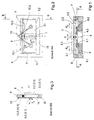
- the gap 1 shows the assembly according to the invention for producing an optically active gap 1 with a variable gap width s.
- the gap 1 is formed between two jaws 2.1 and 2.2, which are arranged displaceably in the directions R 1 and R 2 .
- the split jaws 2.1 and 2.2 are above assigned slides 3.1 and 3.2, to which they are attached, with a Actuator 4 in connection with elliptical surfaces 4.1 and 4.2 provided and mounted rotatably about an axis of rotation 5 is.
- the axis of rotation 5 can be the distances between the elliptical surfaces 4.1 and 4.2 and the axis of rotation 5 can be changed.
- a guide rail 7 serves this purpose, which with the help of a clamping device 8 (see FIG. 2) on one Frame 9 is positioned fixed to the frame.
- a clamping device 8 see FIG. 2
- Guideways 10.1 and 10.2 formed in opposite directions Self-supporting directions from the clamping position cantilever.
- the slider 3.1.3.2 can alternatively both via sliding also via roller pairings with the guideways 10.1,10.2 be connected; according to a design variant the invention is based on a Slide pairing explained.
- the guideways 10.1,10.2 are circular Cross sections on, while on the slides 3.1.3.2 V-grooves are provided against the guideways 10.1,10.2 slide. Receives a relatively low-friction pairing one, for example, if the surface of the V-grooves and / or the guideways 10.1, 10.2 with a DLC layer are provided.
- the groove base 11 of the V-grooves is in Fig.2 shown as a dashed line.
- Figure 2 are the side view of the slide 3.1.3.2, the guide rod 7 with the guideways 10.1,10.2 and the clamping device 8 can be seen in which the guide rod 7 is clamped in the middle.
- Figure 3 a section BB from Figure 2 is the circular Cross section of the guide rail 7 can be seen. This is in the clamping device 8 (with almost play-free sliding fit) recessed and can be tightened with a tension screw (not shown) are clamped.
- tension springs 12.1 and 12.2 are provided, each with one of its ends on a bolt 13 (see Fig. 2 and Fig. 3).
- the bolt 13 is arranged on the frame 9 and thus fixed to the frame. With their opposite The ends are the tension springs 12.1, 12.2 on bolts 14 hung, which is approximately in the geometric center of the Slider 3.1.3.2 are positioned.
- On the bolt 14 are also arranged the inner rings of the ball bearings 6.1.6.2.
- Each of the two tension springs 12.1, 12.2 thus acts with a force component F 1 in the direction of the guide rail 7 and thus causes the V-groove to rest securely on the associated guide path 10.1, 10.2 for each of the two slides 3.1, 3.2.
- each acting a spring force component F 2 in the direction of displacement of the slider 3.1,3.2, and such that the direction of action of the components of F 2 the adjustment directions R 1 and R 2 (see. Fig.1) opposite and thus the contact of the outer rings of the ball bearings 6.1 , 6.2 is secured against the elliptical surfaces 4.1.4.2.
- the side view of the elliptical surfaces 4.1.4.2 on the actuator 4 form an elliptical curve 15, which is shown in FIG. 2 as a dashed line.
- the actuator 4 If the actuator 4 is rotated so that the distances between the elliptical surfaces 4.1.4.2 to the axis of rotation 5 decrease, then the components F 2 act as restoring forces by which the slides 3.1.3.2 are displaced in the opposite direction to the directions R 1 and R 2 and Width s of column 1 is reduced.
- the spring constant of the two tension springs 12.1, 12.2 should be selected such that the force components F 1 are approximately the same size in all the sliding positions of the slides 3.1, 3.2.
- a major advantage of such an arrangement is that the spring components F 1 and F 2 act symmetrically on the split jaws 2.1, 2.2 and thus prevent them from tilting.
- the guideways 16.1,16.2 are as in the first example Assigned slider 3.1.3.2. On these guideways 16.1,16.2 the straight line of the slider 3.1,3.2 or the split jaws 2.1.2.2 achieved analogously to the first example.
- the gap 1 is aligned at right angles to the guide rail 17.
- the parallelism of the gap 1 (assuming, of course, a high level of skill accuracy of all parts of the assembly) is guaranteed precisely when the guideways 16.1, 16.2 are aligned with one another.
- a grub screw 20 is inserted as an actuating element in the frame 9, approximately in the middle between the clamping position 18 and the sliding fit 19, the feed direction of which R 3 is labeled.
- V-grooves not consistently formed on the slides 3.1,3.2, but are milled between their ends, which makes one Tilting of the slider 3.1.3.2 prevented in the direction of displacement becomes.
- FIG. 5 shows the attack of the threaded pin 20 on the guide rail 17 in a side view from FIG. 4.
Landscapes
- Life Sciences & Earth Sciences (AREA)
- Health & Medical Sciences (AREA)
- Surgery (AREA)
- Biophysics (AREA)
- Ophthalmology & Optometry (AREA)
- Engineering & Computer Science (AREA)
- Biomedical Technology (AREA)
- Heart & Thoracic Surgery (AREA)
- Medical Informatics (AREA)
- Molecular Biology (AREA)
- Physics & Mathematics (AREA)
- Animal Behavior & Ethology (AREA)
- General Health & Medical Sciences (AREA)
- Public Health (AREA)
- Veterinary Medicine (AREA)
- Bearings For Parts Moving Linearly (AREA)
- Eye Examination Apparatus (AREA)
- Mechanical Light Control Or Optical Switches (AREA)
- Securing Globes, Refractors, Reflectors Or The Like (AREA)
- Spectrometry And Color Measurement (AREA)
Abstract
Description
- Fig.1
- die Prinzipdarstellung einer ersten Ausgestaltungsvariante in einer Draufsicht
- Fig.2
- einen Schnitt AA aus Fig.1
- Fig.3
- einen Schnitt BB aus Fig.2
- Fig.4
- die Prinzipdarstellung einer zweiten Ausgestaltungsvariante
- Fig.5
- einen Schnitt CC aus Fig.4
- 1
- Spalt
- 2.1, 2.2
- Spaltbacken
- 3.1, 3.2
- Schieber
- 4
- Stellglied
- 4.1, 4.2
- Ellipsenstellflächen
- 5
- Drehachse
- 6.1, 6.2
- Kugellager
- 7
- Führungsschiene
- 8
- Spanneinrichtung
- 9
- Rahmen
- 10.1,10.2
- Führungsbahnen
- 11
- Nutgrund
- 12.1,12.2
- Zugfedern
- 13, 14
- Bolzen
- 15
- Anschlagleiste
- 16.1,16.2
- Führungsbahnen
- 17
- Führungsschiene
- 18
- Einspannposition
- 19
- Gleitpassung
- 20
- Gewindestift
- 21
- Kurve
Claims (12)
- Baugruppe zur Erzeugung eines optisch wirksamen Spaltes mit veränderbarer Spaltbreite s, mit zwei an einer Geradführung gegeneinander verschiebbaren Spaltbacken, zwischen denen der Spalt ausgebildet ist, wobei jeder Spaltbacke eine von zwei Führungsbahnen zugeordnet ist, dadurch gekennzeichnet, daß die Führungsbahnen an Abschnitten einer Führungsschiene ausgebildet sind, die von einer gestellfesten Einspannposition ausgehend in die Verschieberichtungen der Spaltbacken frei vorstehen.
- Baugruppe nach Anspruch 1, dadurch gekennzeichnet, daß die Führungsbahnen (10.1,10.2) an zwei Abschnitten einer Führungsschiene (7) ausgebildet sind, die von einer Spanneinrichtung (8) ausgehend in einander entgegengesetzte Richtungen freitragend vorstehen.
- Baugruppe nach Anspruchs 1, dadurch gekennzeichnet, daß die Führungsbahnen (16.1,16.2) an zwei Abschnitten einer Führungsschiene (17) ausgebildet sind, die von einer Einspannposition (18) ausgehend in eine Richtung vorstehen, wobei der der Einspannposition (18) gegenüberliegende Endabschnitt der Führungsschiene (17) schwimmend gelagert ist.
- Baugruppe nach Anspruch 3, dadurch gekennzeichnet, daß mittig zwischen der Einspannposition (18) und dem gegenüberliegenden schwimmend gelagerten Endabschnitt der Führungsschiene (17) Mittel zur Durchbiegung der Führungsschiene (17) vorhanden sind, wobei mit der Durchbiegung die Fluchtung der beiden Führungsbahnen (16.1,16.2) beeinflußbar ist.
- Vorrichtung nach Anspruch 4, dadurch gekennzeichnet, daß als Mittel zur Durchbiegung ein Gewindestift (20) vorgesehen ist, wobei Gewindestift (20) und Führungsschiene (7) aus Material mit gleichem Ausdehnungskoeffizienten gefertigt sind.
- Baugruppe nach einem der vorgenannten Ansprüche, dadurch gekennzeichnet, daß den Führungsbahnen (10.1,10.2;16.1,16.2) Schieber (3.1,3.2) gegenüberstehen, die mit Gleit- oder Wälzkörperführungen ausgestattet sind und an denen die Spaltbacken (2.1,2.2) befestigt sind.
- Baugruppe nach Anspruch 6, dadurch gekennzeichnet, daß an den Schiebern (3.1,3.2) Wälzkörperführungen vorgesehen sind, die die Führungsbahnen (10.1,10.2;16.1,16.2) umgreifen.
- Baugruppe nach Anspruch 6, dadurch gekennzeichnet, daß an den Schiebern (3.1,3.2) V-Nuten vorgesehen sind, die gegen die Führungsbahnen (10.1,10.2;16.1,16.2) gleiten.
- Baugruppe nach Anspruch 8, dadurch gekennzeichnet, daß Zug- und/oder Druckfedern zur Erzeugung einer Vorspannkraft zwischen den Schiebern (3.1,3.2) und den Führungsbahnen (10.1,10.2;16.1,16.2) vorhanden sind, wobei jeweils ein Federende gestellfest und das andere Federende an einem der Schieber (3.1,3.2) eingehängt ist.
- Baugruppe nach Anspruch 9, dadurch gekennzeichnet, daß Zugfedern (12.1,12.2) vorgesehen und so angeordnet sind, daß die Federkraft mit einer ersten Komponente F1 die Vorspannung der Schieber (3.1,3.2) gegen die Führungsbahnen (10.1,10.2;16.1,16.2) und mit einer zweiten Komponente F2 eine Vorspannung der Schieber (3.1,3.2) gegen an einem Stellglied (4) ausgebildete Ellipsenstellflächen (4.1,4.2) bewirkt, die zur Einstellung eines Abstandes zwischen den Schiebern (3.1,3.2) in Verschieberichtung und damit zur Einstellung der Spaltbreite s vorgesehen sind.
- Baugruppe nach Anspruch 10, dadurch gekennzeichnet, daß die Zugfedern (12.1,12.2) so angeordnet sind, daß die Federkraft mit einer dritten Komponente F3 die Vorspannung der Schieber (3.1,3.2) gegen eine Anschlagleiste (15) bewirkt, wodurch eine Drehung der Spaltbacken (2.1,2.2) um die Verschieberichtung verhindert ist.
- Baugruppe nach Anspruch 10 oder 11, dadurch gekennzeichnet, daß zur Aufnahme der Vorspannkraft bzw. zur Minimierung der Reibung zwischen den Ellipsenstellflächen (4.1,4.2) und den Schiebern (3.1,3.2) Wälzlager (6.1,6.2) vorgesehen sind.
Applications Claiming Priority (2)
| Application Number | Priority Date | Filing Date | Title |
|---|---|---|---|
| DE19910942A DE19910942A1 (de) | 1999-03-12 | 1999-03-12 | Baugruppe zur Erzeugung eines optisch wirksamen Spaltes |
| DE19910942 | 1999-03-12 |
Publications (2)
| Publication Number | Publication Date |
|---|---|
| EP1043575A2 true EP1043575A2 (de) | 2000-10-11 |
| EP1043575A3 EP1043575A3 (de) | 2002-02-27 |
Family
ID=7900657
Family Applications (1)
| Application Number | Title | Priority Date | Filing Date |
|---|---|---|---|
| EP00101046A Withdrawn EP1043575A3 (de) | 1999-03-12 | 2000-01-20 | Baugruppe zur Erzeugung eines optisch wirksamen Spaltes |
Country Status (4)
| Country | Link |
|---|---|
| US (1) | US6252696B1 (de) |
| EP (1) | EP1043575A3 (de) |
| JP (1) | JP2000287932A (de) |
| DE (1) | DE19910942A1 (de) |
Families Citing this family (4)
| Publication number | Priority date | Publication date | Assignee | Title |
|---|---|---|---|---|
| ATE512356T1 (de) * | 2001-04-06 | 2011-06-15 | Renishaw Plc | Optische blende |
| DE102004005390A1 (de) * | 2004-02-04 | 2005-08-25 | Carl Zeiss Jena Gmbh | Verstellbare optische Spaltblende |
| JP4531413B2 (ja) * | 2004-02-10 | 2010-08-25 | 株式会社トプコン | 細隙灯顕微鏡 |
| CN115560851B (zh) * | 2022-09-22 | 2023-05-23 | 上海元析仪器有限公司 | 一种可空间滤波的光谱仪器用自动变狭缝装置 |
Family Cites Families (8)
| Publication number | Priority date | Publication date | Assignee | Title |
|---|---|---|---|---|
| US2664028A (en) * | 1948-12-31 | 1953-12-29 | American Optical Corp | Slit mechanism |
| US2582410A (en) * | 1949-05-03 | 1952-01-15 | American Optical Corp | Slit mechanism |
| US3393959A (en) * | 1963-06-06 | 1968-07-23 | Conductron Corp | Light aperture construction |
| FR2030685A5 (de) * | 1969-11-25 | 1970-11-13 | Baldy Andre | |
| US4047808A (en) * | 1975-08-13 | 1977-09-13 | Varian Techtron Proprietary Limited | Adjustable slit mechanism |
| JPH06100498B2 (ja) * | 1987-03-06 | 1994-12-12 | 日本分光株式会社 | スリツト装置 |
| JPH07111143A (ja) * | 1993-08-18 | 1995-04-25 | Jeol Ltd | スリット装置 |
| US5661589A (en) * | 1995-02-24 | 1997-08-26 | J. A. Woollam Co. Inc. | Bilateral slit assembly, and method of use |
-
1999
- 1999-03-12 DE DE19910942A patent/DE19910942A1/de not_active Withdrawn
-
2000
- 2000-01-20 EP EP00101046A patent/EP1043575A3/de not_active Withdrawn
- 2000-03-08 JP JP2000062968A patent/JP2000287932A/ja active Pending
- 2000-03-10 US US09/522,546 patent/US6252696B1/en not_active Expired - Fee Related
Also Published As
| Publication number | Publication date |
|---|---|
| EP1043575A3 (de) | 2002-02-27 |
| US6252696B1 (en) | 2001-06-26 |
| JP2000287932A (ja) | 2000-10-17 |
| DE19910942A1 (de) | 2000-09-14 |
Similar Documents
| Publication | Publication Date | Title |
|---|---|---|
| DE2952078C2 (de) | Einrichtung zur spielfreien Kurvensteuerung | |
| DE2941475A1 (de) | Linearlagervorrichtung | |
| EP2540438A1 (de) | Lünette | |
| DE3650509T2 (de) | Zoom-Mikroskop mit Kurbel und Gestängemechanismus | |
| DE102011000404B4 (de) | Umkehrsystem mit zweigeteilter Hülse in Kulissenform | |
| DE19910942A1 (de) | Baugruppe zur Erzeugung eines optisch wirksamen Spaltes | |
| EP0416354B2 (de) | Schlitten-Mikrotom | |
| DE102008033425A1 (de) | Stranggranulator mit Schneidspaltverstellung | |
| WO1999040469A1 (de) | Zylindrische fassung für verstellbare optische bauelemente | |
| EP2365274B1 (de) | Zielfernrohr mit einer Umkehrsystem-Lagerung | |
| EP2674248B1 (de) | Finishvorrichtung | |
| EP1144153B1 (de) | Feststelleinrichtung zum klemmen einer welle oder stange | |
| DE69533111T2 (de) | Vorrichtung zur führung von mikroskoplinsen | |
| EP1963902B1 (de) | Anordnung zur verstellung von optischen komponenten und/oder linsengruppen, in variabbildungssystemen | |
| AT507016A1 (de) | Linearführung | |
| DE19815692B4 (de) | Kettenspanner | |
| DE10323386B4 (de) | Linearführungseinheit | |
| DE1602423C3 (de) | Biege- und Stanzautomat zum Herstellen von Formteilen aus Draht oder Band | |
| DE19804472C1 (de) | Spielfreie Geradführung | |
| DE102012010632B4 (de) | Stellvorrichtung zur Ausführung einer Stellbewegung mittels einer Antriebsspindel und Anwendungssystem mit einer solchen Stellvorrichtung | |
| DE2547437C2 (de) | Vorrichtung zur Justierung zweier optischer Bauelemente | |
| DE19808467A1 (de) | Rundstabführung | |
| DE1210207B (de) | Vorrichtung zum gleichzeitigen Verstellen zweier Spalte bei einem optischen Geraet mit an biegsamen Blattfedern befestigten beweglichen Spaltbacken | |
| DE69217667T2 (de) | Gleitschienenaufbau | |
| DE1772922C (de) | Vorrichtung zur Herstellung stereoskopischer Bilder |
Legal Events
| Date | Code | Title | Description |
|---|---|---|---|
| PUAI | Public reference made under article 153(3) epc to a published international application that has entered the european phase |
Free format text: ORIGINAL CODE: 0009012 |
|
| 17P | Request for examination filed |
Effective date: 20000120 |
|
| AK | Designated contracting states |
Kind code of ref document: A2 Designated state(s): CH DE GB IT LI |
|
| AX | Request for extension of the european patent |
Free format text: AL;LT;LV;MK;RO;SI |
|
| PUAL | Search report despatched |
Free format text: ORIGINAL CODE: 0009013 |
|
| AK | Designated contracting states |
Kind code of ref document: A3 Designated state(s): CH DE GB IT LI |
|
| AX | Request for extension of the european patent |
Free format text: AL;LT;LV;MK;RO;SI |
|
| AKX | Designation fees paid |
Free format text: CH DE GB IT LI |
|
| STAA | Information on the status of an ep patent application or granted ep patent |
Free format text: STATUS: THE APPLICATION IS DEEMED TO BE WITHDRAWN |
|
| 18D | Application deemed to be withdrawn |
Effective date: 20050802 |