EP1043122A2 - Apparatus and method for continuous delivery and conditioning of a polishing slurry - Google Patents
Apparatus and method for continuous delivery and conditioning of a polishing slurry Download PDFInfo
- Publication number
- EP1043122A2 EP1043122A2 EP00302562A EP00302562A EP1043122A2 EP 1043122 A2 EP1043122 A2 EP 1043122A2 EP 00302562 A EP00302562 A EP 00302562A EP 00302562 A EP00302562 A EP 00302562A EP 1043122 A2 EP1043122 A2 EP 1043122A2
- Authority
- EP
- European Patent Office
- Prior art keywords
- slurry
- mixing chamber
- polishing
- chemical
- sensor system
- Prior art date
- Legal status (The legal status is an assumption and is not a legal conclusion. Google has not performed a legal analysis and makes no representation as to the accuracy of the status listed.)
- Ceased
Links
Images


Classifications
-
- B—PERFORMING OPERATIONS; TRANSPORTING
- B24—GRINDING; POLISHING
- B24B—MACHINES, DEVICES, OR PROCESSES FOR GRINDING OR POLISHING; DRESSING OR CONDITIONING OF ABRADING SURFACES; FEEDING OF GRINDING, POLISHING, OR LAPPING AGENTS
- B24B37/00—Lapping machines or devices; Accessories
- B24B37/04—Lapping machines or devices; Accessories designed for working plane surfaces
-
- H—ELECTRICITY
- H10—SEMICONDUCTOR DEVICES; ELECTRIC SOLID-STATE DEVICES NOT OTHERWISE PROVIDED FOR
- H10P—GENERIC PROCESSES OR APPARATUS FOR THE MANUFACTURE OR TREATMENT OF DEVICES COVERED BY CLASS H10
- H10P52/00—Grinding, lapping or polishing of wafers, substrates or parts of devices
-
- B—PERFORMING OPERATIONS; TRANSPORTING
- B24—GRINDING; POLISHING
- B24B—MACHINES, DEVICES, OR PROCESSES FOR GRINDING OR POLISHING; DRESSING OR CONDITIONING OF ABRADING SURFACES; FEEDING OF GRINDING, POLISHING, OR LAPPING AGENTS
- B24B57/00—Devices for feeding, applying, grading or recovering grinding, polishing or lapping agents
- B24B57/02—Devices for feeding, applying, grading or recovering grinding, polishing or lapping agents for feeding of fluid, sprayed, pulverised, or liquefied grinding, polishing or lapping agents
Definitions
- the present invention is directed, in general, to a polishing apparatus and method of use of that apparatus and, more specifically, to an apparatus and method for preparing, conditioning, and delivering of a polishing slurry used in the chemical mechanical planarization of semiconductor wafers during the polishing process.
- the various devices are formed in layers upon an underlying substrate that is typically composed of silicon, germanium, or gallium arsenide.
- the discrete devices are interconnected by metal conductor lines to form the desired integrated circuits.
- the metal conductor lines are further insulated from the next interconnection level by thin films of insulating material deposited by, for example, CVD (Chemical Vapor Deposition) of oxide or application of SOG (Spin On Glass) layers followed by fellow processes.
- CVD Chemical Vapor Deposition
- SOG Spin On Glass
- CMP Chemical/mechanical polishing
- insulator surfaces such as silicon oxide or silicon nitride, deposited by chemical vapor deposition
- insulating layers such as glasses deposited by spin-on and reflow deposition means, over semiconductor devices
- metallic conductor interconnection wiring layers metallic conductor interconnection wiring layers.
- CMP involves holding and rotating a thin, reasonably flat, semiconductor wafer against a rotating polishing surface.
- the polishing surface is wetted by a chemical slurry, under controlled chemical, pressure, and temperature conditions.
- the chemical slurry contains a polishing agent, which is an abrasive material, and chemicals chosen to selectively etch or oxidize particular surfaces of the wafer during CMP. It may be desirable to perform the chemical etching and mechanical abrasion steps simultaneously or sequentially.
- the combination of chemical etching and mechanical removal of material during polishing results in superior planarization of the polished surface.
- polishing slurry is a suspension of a mechanical abrasive in a liquid chemical agent
- the suspension is normally premixed as a batch and stored in a batch tank of about 350 gallon capacity.
- the premix tank is connected to another tank, commonly called a "day tank,” of about 50 gallon capacity by an extensive plumbing system.
- the plumbing system allows the slurry to be continuously recirculated between the day tank and the premix tank. This approach hopes to minimize settling and agglomeration of the particulates in suspension and maintain a reasonably uniform mixture.
- a single batch of slurry may have a volume of about 350 gallons. Once mixed, the slurry "brew" needs from about one-half hour to 12 hours of vigorous agitation/recirculation before the slurry is useable in order to insure reasonable uniformity.
- the effectiveness of the CMP process depends significantly upon the physical parameters, for example: chemical concentration, temperature, pH, specific gravity, etc., of the slurry. Because of the large slurry volume, i.e., 350 gallons, it is extremely difficult to make small adjustments to the mixture in a timely manner. Additionally, the large volume of slurry commits the CMP equipment to a particular process, e.g., planarization of a metal layer, because of the incompatibility of the chemicals in a particular slurry mix to the planarization of a different material, e.g., a dielectric. Modification of the chemical properties of the total slurry mix is very difficult. Therefore, a large quantity of highly refined and expensive chemicals must be ultimately used, stored or disposed.
- a slurry preparation apparatus that: provides a continuous slurry delivery system, constantly monitors the slurry parameters, and continually adjusts the slurry components to correct the slurry parameters to nominal values.
- the present invention provides a continuous slurry delivery system for use with a polishing apparatus employing a slurry.
- the continuous slurry delivery system comprises a mixing chamber, slurry component tanks, a chemical parameter sensor system, and a control system.
- Each of the slurry component tanks contains a different slurry component and is in fluid connection with the mixing chamber to deliver a required rate of the different slurry component to the mixing chamber.
- the chemical parameter sensor system is coupled to the mixing chamber and configured to sense a chemical property of the slurry.
- the control system is coupled to the mixing chamber and the chemical parameter sensor system. The control system is configured to control the introduction of at least one of the slurry components at a given rate to the mixing chamber.
- the present invention provides a slurry dispensing system that allows the slurry composition to be easily changed or adjusted as processes parameters require. This system, therefore, allows for a more continuous polishing and fabrication process, which also reduces fabrication costs and increases overall production efficiency.
- the chemical property sensed may be an ion concentration or conductivity.
- the ion sensed may be: hydronium ion (H 3 O + ), hydroxyl ion (OH - ) metal ion, or non-metal ion concentration.
- the different slurry components may be: an oxidant, a surfactant, an abrasive, a buffer, a corrosion inhibitor, an acid, a base, or water, which are typically used during the polishing of a semiconductor wafer.
- the mixing chamber may comprise a pre-mixing chamber and the continuous slurry delivery system further comprises a pre-dispensing chamber in fluid connection with the pre-mixing chamber.
- the chemical parameter sensor system may be coupled to the pre-mixing chamber or the pre-dispensing chamber.
- the continuous slurry delivery system may further comprise a physical parameter sensor system that is coupled to the mixing chamber and that is configured to sense a physical property of the slurry.
- exemplary physical properties that may be sensed are: pressure, temperature, humidity, density, viscosity, zeta potential and light transmittance for turbidity.
- the mixing chamber may further comprise an agitator for mixing the slurry.
- the slurry component tanks may, in another embodiment, further comprise a meter device configured to meter a measured rate of the different slurry component into the mixing chamber.
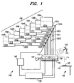
- a continuous slurry delivery system 100 comprises a mixing chamber 110, a slurry dispenser 115, slurry component tanks collectively designated 120 and individually designated 120a-120h, a chemical parameter sensor system 130, and a control system 140.
- the mixing chamber 110 has a volume that is relatively small when compared to the total volume of the delivery system.
- the mixing chamber 110 may have a volume of about 0.5 gallons where the total system volume may be as much as 350 gallons.
- larger volumes for the mixing chamber 110 are also within the scope of the present invention.
- Each of the slurry component tanks 120a-120h contains a different slurry component essential to the overall polishing and conditioning processes; for example, an oxidant 121a, a surfactant 121b, an abrasive 121c, a buffer 121d, a corrosion inhibitor 121e, an acid 121f, a base 121g, or water 121h.
- a different slurry component essential to the overall polishing and conditioning processes for example, an oxidant 121a, a surfactant 121b, an abrasive 121c, a buffer 121d, a corrosion inhibitor 121e, an acid 121f, a base 121g, or water 121h.
- the slurry component tanks 120a-120h are individually in fluid communication with the mixing chamber 110.
- fluid communication means having a conduit 122a-122h between the individual component tanks 120a-120h and the mixing chamber 110 that is suitable for conducting the component from each component tank 120a-120h to the mixing chamber 110.
- fluids such as water 121h
- fluids may have a tube 122h directly connecting to the mixing chamber 110.
- a metering device 123a-123h that is configured to meter a measured rate of the respective component 121a-121h into the mixing chamber 110.
- the mixing chamber 110 further comprises an agitator 150 that concusses the contents of the chamber 110 so as to produce a substantially uniform slurry 160 that is delivered to a polishing platen/pad 170 of a polishing apparatus 180.
- the slurry 150 is a chemical suspension of some of the individual components 121a-121h described above.
- One who is skilled in the art is aware that the exact composition of the slurry 160 will vary depending upon what material is to be planarized.
- the chemical parameter sensor system 130 is coupled to the mixing chamber 110 and, through sensors 135, configured to sense a chemical property, for example, an ion concentration or conductivity of the slurry 160. More specifically, the chemical property sensed may be a hydronium (H 3 O + ), hydroxyl ion (OH - ) metal, or non-metal ion concentration; or oxidant concentration.
- a chemical property for example, an ion concentration or conductivity of the slurry 160. More specifically, the chemical property sensed may be a hydronium (H 3 O + ), hydroxyl ion (OH - ) metal, or non-metal ion concentration; or oxidant concentration.
- This ion concentration, or another chemical or physical property, is analyzed by the control system 140, which determines what chemical components 121a-121h are deficient or excessive in the slurry 160, and sends a command to one or more of the metering devices 123a-123h to introduce the appropriate chemical components 121a-121h into the mixing chamber 110 at an appropriate rate to adjust the slurry 160 composition.
- the chemical parameter sensor system 130 may, during polishing of a metal, determine that the initial pH of the slurry 160 is 4.7.
- the desired pH for the process may be 4.5.
- the control system 140 would compare the actual pH of 4.7 to the desired 4.5 and command the metering device 123f to introduce a calculated rate of acid 121f from acid component tank 120f into the mixing chamber 110.
- the slurry 160 composition will vary only slightly from the desired parameters.
- the close controlling of the slurry 160 composition speeds the CMP process and improves semiconductor wafer throughput.
- the mixing chamber 110 and slurry dispenser 115 can quickly be flushed and prepared to change over to a different process, e.g., from metal polishing to dielectric polishing.
- the large batch size of the prior art is therefore avoided; and the disposal of excess slurry mixture is avoided while slurry components are kept isolated from one another.
- the chemicals 121a-121h are retained in the individual component tanks 120a-120h until they are needed in relatively small quantities, thereby avoiding the waste of potentially hazardous chemicals that, once mixed, cannot be economically separated.
- the continuous slurry delivery system 100 may further comprise a physical parameter sensor system 190 coupled to the mixing chamber 110 and the control system 140.
- the physical parameter sensor system 190 may collect current data on, for example, the temperature, pressure, humidity, turbidity, density, viscosity, zeta potential, etc., of the slurry mixing chamber 110.
- the control system 140 processes this information and makes needed adjustments to the environment. For example, the actual environmental temperature may be 50°C, when the desired temperature is 55°C.
- the control system 140 sensing the difference, then commands a heater 193 to increase the environmental temperature until 55°C is reached.
- the slurry temperature is the controlling factor, then it may also be sensed as just described, and adjusted by, for example, a cold or hot water bath 195 around the mixing chamber 110.
- a cold or hot water bath 195 around the mixing chamber 110 One who is skilled in the art is familiar with the methods of controlling physical parameters of suspensions.
- the continuous slurry delivery system 100 may further comprise a pressurizing system (not shown) and directable pressure nozzle for delivery of a selected one or more of the components to the polishing platen/pad 170, such as water or other cleaning fluid.
- the pressurized system can be used to clean and condition the polishing pad between various polishing operations.
- pressurized fluid delivery systems that could be used in this aspect of the present invention.
- the continuous slurry delivery system 200 may comprise a pre-mixing chamber 211 and a pre-dispensing chamber 212. Slurry mixing from the individual components 121a-121h occurs in the pre-mixing chamber 211. The slurry 160 is then delivered to the pre-dispensing chamber 212, whence the slurry 160 is dispensed onto the polishing platen/pad 170.
- a chemical parameter sensor system 230 and a physical parameter sensing system 290a, 290b may be coupled to both the pre-mixing chamber 211, as in 290b, and the pre-dispensing chamber 212, as in 290a.
- portions of the sensing systems 230, 290a, 290b may be distributed as desired for optimum performance.
- the advantages of locating particular sensors on either the pre-mixing chamber 211 or the pre-dispensing chamber 212 is readily understood by one who is skilled in the art and does not effect the scope of the present invention.
- FIGURE 3 illustrated is an elevational view of the continuous slurry delivery system of FIGURE 1 in use with a semiconductor polishing apparatus.
- a semiconductor wafer 310 has been installed in a polishing head 320 of a polishing apparatus 380.
- the semiconductor wafer 310 may be at any stage of manufacture requiring planarization, e.g., substrate, metal layer, microcircuit formed, dielectric layer, etc.
- the chemical parameter sensing system 130 continually monitors chemical parameters prescribed, and necessary adjustments to the rate of dispensing of slurry components 121a-121h are made by the control system 140 to maintain the actual chemical parameters within very close tolerance of the desired parameters.
- the physical parameter sensor system 190 senses the actual value of prescribed physical parameters and adjustments are made by the control system 140 as described above.
- the semiconductor wafer 310 is polished in a conventional manner well known to one who is skilled in the art. Significantly, only minimal quantities of the slurry 160, on the order of 2 liters, are ever mixed at any one time. Thus, mixing slurry 160 far in excess of the current need is avoided, as well as waste and potential pollution. Disposal of unneeded slurry 160 is minimized and costs are significantly reduced. Changing from substrate, to metal, to dielectric planarization processes is accomplished rapidly and at minimal cost.
Landscapes
- Engineering & Computer Science (AREA)
- Mechanical Engineering (AREA)
- Mechanical Treatment Of Semiconductor (AREA)
- Grinding-Machine Dressing And Accessory Apparatuses (AREA)
- Finish Polishing, Edge Sharpening, And Grinding By Specific Grinding Devices (AREA)
Abstract
Description
Claims (12)
- For use with a polishing apparatus employing a slurry, a continuous slurry delivery system, comprising:a mixing chamber;slurry component tanks, each of said slurry component tanks for containing a different slurry component for delivery at a required rate of said different slurry component to said mixing chamber;a sensor system for sensing a chemical property or parameter of said slurry; anda control system coupled to said chemical parameter sensor system and said mixing chamber, said control system configured to introduce at least one of said slurry components at a given rate.
- A method of forming a continuous slurry for a semiconductor polishing system, comprising:dispensing a slurry component at a required rate into a mixing chamber from at least one of slurry component tanks in fluid connection with said mixing chamber, each of said slurry component tanks containing a different slurry component;sensing a chemical parameter of said slurry with a chemical parameter sensor system;dispensing at least one of another of said slurry components into said mixing chamber at a given rate by way of a control system coupled to said chemical parameter sensor system.
- The system of claim 1, or the method of claim 2, wherein said chemical property or parameter is an ion concentration or conductivity.
- The system or method of claim 3, wherein said ion concentration is selected fromhydronium ion concentration,hydroxyl ion concentration,metal ion concentration, andnon-metal ion concentration.
- The system of claim 1, or the method of claim 2, wherein said different slurry components are selected froman oxidant,a surfactant,an abrasive,a buffer,a corrosion inhibitor,an acid,a base, andwater.
- The system of claim 1 or the method of claim 2, wherein said mixing chamber is a pre-mixing chamber, and the system further comprises a pre-dispensing chamber in connection with said pre-mixing chamber, said pre-mixing chamber having a volume substantially less than a volume of said slurry delivery system.
- The system or method of claim 6, wherein said chemical parameter sensor system is coupled to said pre-mixing chamber or said pre-dispensing chamber.
- The system of claim 1, or the method of claim 2, further comprising a physical parameter sensor system coupled to said control system and/or said mixing chamber, said physical parameter sensor system configured to sense a physical property of said slurry, and said control system is configured to adjust a physical parameter of said slurry.
- The system or method of claim 8, wherein said physical property is selected from the group consisting of:pressure,temperature,humidity,density,viscosity,zeta potential, andlight transmittance.
- The system of claim 1, or the method of claim 2, wherein said mixing chamber further comprises an agitator for mixing said slurry, and/or wherein each of said slurry component tanks further comprise a meter device configured to meter a measured rate of said different slurry component, and/or the system further comprises a pressurized delivery system in fluid connection with said slurry delivery system and configured to deliver a pressurized fluid through a nozzle onto a polishing pad.
- A method of fabricating a semiconductor wafer, comprising:forming a material layer on a semiconductor substrate;retaining said semiconductor substrate in a polishing head of a polishing apparatus;delivering a continuous slurry to a platen of said polishing apparatus by:dispensing a slurry component at a required rate into a mixing chamber from at least one of slurry component tanks in fluid connection with said mixing chamber, each of said slurry component tanks containing a different slurry component;sensing a chemical parameter of said slurry with a chemical parameter sensor system coupled to said mixing chamber; anddispensing at least one of another of said slurry components into said mixing chamber at a given rate by way of a control system coupled to said chemical parameter sensor system; andpolishing said material layer against said polishing platen.
- The method as recited in claim 11, wherein polishing includes polishing a substrate, a dielectric layer or a metal layer, and/or forming interconnected integrated circuits on said semiconductor wafer.
Applications Claiming Priority (2)
| Application Number | Priority Date | Filing Date | Title |
|---|---|---|---|
| US09/286,869 US6048256A (en) | 1999-04-06 | 1999-04-06 | Apparatus and method for continuous delivery and conditioning of a polishing slurry |
| US286869 | 1999-04-06 |
Publications (2)
| Publication Number | Publication Date |
|---|---|
| EP1043122A2 true EP1043122A2 (en) | 2000-10-11 |
| EP1043122A3 EP1043122A3 (en) | 2003-04-16 |
Family
ID=23100520
Family Applications (1)
| Application Number | Title | Priority Date | Filing Date |
|---|---|---|---|
| EP00302562A Ceased EP1043122A3 (en) | 1999-04-06 | 2000-03-28 | Apparatus and method for continuous delivery and conditioning of a polishing slurry |
Country Status (6)
| Country | Link |
|---|---|
| US (1) | US6048256A (en) |
| EP (1) | EP1043122A3 (en) |
| JP (2) | JP2000308957A (en) |
| KR (1) | KR20010020713A (en) |
| SG (1) | SG97878A1 (en) |
| TW (1) | TW467806B (en) |
Cited By (4)
| Publication number | Priority date | Publication date | Assignee | Title |
|---|---|---|---|---|
| DE102004005741A1 (en) * | 2004-02-05 | 2005-09-01 | Infineon Technologies Ag | Polishing cloth refining method, involves rubbing off surface of cloth with tool, compiling refining conditions of cloth using parameters, monitoring conditions and terminating refining of cloth when specified condition is achieved |
| US20200298371A1 (en) * | 2014-09-30 | 2020-09-24 | Taiwan Semiconductor Manufacturing Co., Ltd. | Slurry dispersion system with real time control |
| US20200338688A1 (en) * | 2019-04-25 | 2020-10-29 | Lth Co., Ltd. | Method for automatically verifying and cleaning large-sized particle counter for analyzing cmp slurry and verification system suitable for same |
| EP3888779A1 (en) * | 2016-03-11 | 2021-10-06 | FUJIFILM Electronic Materials U.S.A., Inc. | Advanced fluid processing systems |
Families Citing this family (52)
| Publication number | Priority date | Publication date | Assignee | Title |
|---|---|---|---|---|
| JP2000071172A (en) * | 1998-08-28 | 2000-03-07 | Nec Corp | Apparatus and method for regenerating slurry for chemical mechanical polishing |
| US6280300B1 (en) * | 1998-11-25 | 2001-08-28 | Ebara Corporation | Filter apparatus |
| JP3426149B2 (en) * | 1998-12-25 | 2003-07-14 | 富士通株式会社 | Method and apparatus for recycling polishing waste liquid in semiconductor manufacturing |
| US7180591B1 (en) | 1999-06-03 | 2007-02-20 | Micron Technology, Inc | Semiconductor processors, sensors, semiconductor processing systems, semiconductor workpiece processing methods, and turbidity monitoring methods |
| US6290576B1 (en) | 1999-06-03 | 2001-09-18 | Micron Technology, Inc. | Semiconductor processors, sensors, and semiconductor processing systems |
| US7530877B1 (en) * | 1999-06-03 | 2009-05-12 | Micron Technology, Inc. | Semiconductor processor systems, a system configured to provide a semiconductor workpiece process fluid |
| US6306012B1 (en) * | 1999-07-20 | 2001-10-23 | Micron Technology, Inc. | Methods and apparatuses for planarizing microelectronic substrate assemblies |
| US6179699B1 (en) * | 1999-09-27 | 2001-01-30 | Advanced Micro Devices, Inc. | Shape memory alloy-controlled slurry dispense system for CMP processing |
| EP1094506A3 (en) | 1999-10-18 | 2004-03-03 | Applied Materials, Inc. | Capping layer for extreme low dielectric constant films |
| US6267641B1 (en) | 2000-05-19 | 2001-07-31 | Motorola, Inc. | Method of manufacturing a semiconductor component and chemical-mechanical polishing system therefor |
| JP2002016030A (en) * | 2000-06-27 | 2002-01-18 | Mitsubishi Chemical Engineering Corp | Polishing liquid preparation method and preparation apparatus |
| JP2002016029A (en) * | 2000-06-27 | 2002-01-18 | Mitsubishi Chemical Engineering Corp | Polishing liquid preparation method and preparation apparatus |
| EP1749565A1 (en) * | 2000-07-31 | 2007-02-07 | Kinetics Chempure Systems, Inc. | Method and apparatus for blending process materials |
| US7905653B2 (en) * | 2001-07-31 | 2011-03-15 | Mega Fluid Systems, Inc. | Method and apparatus for blending process materials |
| KR100746414B1 (en) * | 2000-07-31 | 2007-08-03 | 셀레리티 인크. | Mixing method and apparatus of process materials |
| US6431950B1 (en) | 2000-10-18 | 2002-08-13 | Micron Technology, Inc. | Point-of-use fluid regulating system for use in the chemical-mechanical planarization of semiconductor wafers |
| JP2002170792A (en) * | 2000-11-29 | 2002-06-14 | Mitsubishi Electric Corp | Polishing liquid supply apparatus and polishing liquid supply method, polishing apparatus and polishing method, and method of manufacturing semiconductor device |
| US6575823B1 (en) | 2001-03-06 | 2003-06-10 | Psiloquest Inc. | Polishing pad and method for in situ delivery of chemical mechanical polishing slurry modifiers and applications thereof |
| GB2375072A (en) * | 2001-05-05 | 2002-11-06 | Psi Global Ltd | Method and apparatus for making moulded filter elements |
| US20030098069A1 (en) * | 2001-11-26 | 2003-05-29 | Sund Wesley E. | High purity fluid delivery system |
| KR100428787B1 (en) * | 2001-11-28 | 2004-04-28 | 삼성전자주식회사 | Slurry supply appratus having a mixing unit at a point of use and a slurry storage unit |
| DE20205819U1 (en) | 2002-04-12 | 2003-08-21 | Kinetics Germany GmbH, 63863 Eschau | Device for providing high-purity process chemicals |
| KR20020037316A (en) * | 2002-04-23 | 2002-05-18 | 이성희 | Method for controlling tilt servo in a DVD system |
| JP2004006499A (en) * | 2002-05-31 | 2004-01-08 | Mitsubishi Electric Corp | Semiconductor manufacturing apparatus, polishing liquid supply apparatus, method for detecting characteristics of polishing liquid, and method for manufacturing semiconductor device |
| US20040014403A1 (en) * | 2002-07-16 | 2004-01-22 | Oberkampf Brandon L. | CMP point of use filtration |
| US7344298B2 (en) * | 2002-07-19 | 2008-03-18 | Celerity, Inc. | Method and apparatus for blending process materials |
| US20040049301A1 (en) * | 2002-09-10 | 2004-03-11 | M Fsi Ltd. | Apparatus and method for preparing and supplying slurry for CMP machine |
| US6884145B2 (en) | 2002-11-22 | 2005-04-26 | Samsung Austin Semiconductor, L.P. | High selectivity slurry delivery system |
| KR100570371B1 (en) * | 2002-12-30 | 2006-04-11 | 동부아남반도체 주식회사 | Slurry flow control device and method |
| TWI250202B (en) * | 2003-05-13 | 2006-03-01 | Eternal Chemical Co Ltd | Process and slurry for chemical mechanical polishing |
| US7072742B1 (en) * | 2003-10-17 | 2006-07-04 | Technikrom, Inc. | Accurate blending module and method |
| US7515994B2 (en) * | 2003-10-17 | 2009-04-07 | Technikrom, Inc. | Accurate blending module and method |
| US8271139B2 (en) * | 2003-10-17 | 2012-09-18 | Asahi Kasei Bioprocess, Inc. | Multi-stage accurate blending system and method |
| JP4645056B2 (en) * | 2004-03-31 | 2011-03-09 | パナソニック株式会社 | Polishing fluid supply device |
| JP2005340328A (en) * | 2004-05-25 | 2005-12-08 | Fujitsu Ltd | Manufacturing method of semiconductor device |
| EP2125985B1 (en) * | 2006-12-29 | 2012-08-15 | LG Chem, Ltd. | Cmp slurry composition for forming metal wiring line |
| US7651384B2 (en) * | 2007-01-09 | 2010-01-26 | Applied Materials, Inc. | Method and system for point of use recycling of ECMP fluids |
| TW200916183A (en) * | 2007-05-09 | 2009-04-16 | Advanced Tech Materials | Systems and methods for material blending and distribution |
| TW200939335A (en) * | 2007-12-06 | 2009-09-16 | Advanced Tech Materials | Systems and methods for delivery of fluid-containing process material combinations |
| CN102257604B (en) * | 2008-12-20 | 2013-07-03 | 嘉柏微电子材料股份公司 | Wire saw cutting method |
| US8557134B2 (en) | 2010-01-28 | 2013-10-15 | Environmental Process Solutions, Inc. | Accurately monitored CMP recycling |
| US9670809B2 (en) | 2011-11-29 | 2017-06-06 | Corning Incorporated | Apparatus and method for skinning articles |
| TWI641936B (en) * | 2012-11-13 | 2018-11-21 | 美商慧盛材料美國責任有限公司 | Slurry supply and/or chemical blend supply apparatuses, processes, methods of use and methods of manufacture |
| JP2016507896A (en) * | 2013-01-11 | 2016-03-10 | アプライド マテリアルズ インコーポレイテッドApplied Materials,Incorporated | Chemical mechanical polishing apparatus and method |
| US9484211B2 (en) | 2013-01-24 | 2016-11-01 | Taiwan Semiconductor Manufacturing Company, Ltd. | Etchant and etching process |
| US9490133B2 (en) * | 2013-01-24 | 2016-11-08 | Taiwan Semiconductor Manufacturing Company, Ltd. | Etching apparatus |
| US9770804B2 (en) | 2013-03-18 | 2017-09-26 | Versum Materials Us, Llc | Slurry supply and/or chemical blend supply apparatuses, processes, methods of use and methods of manufacture |
| US10611051B2 (en) | 2013-10-15 | 2020-04-07 | Corning Incorporated | Systems and methods for skinning articles |
| US9239296B2 (en) | 2014-03-18 | 2016-01-19 | Corning Incorporated | Skinning of ceramic honeycomb bodies |
| JP2015199134A (en) * | 2014-04-04 | 2015-11-12 | 株式会社ディスコ | Polishing device and polishing method of plate-like object |
| US12017322B2 (en) * | 2018-08-14 | 2024-06-25 | Taiwan Semiconductor Manufacturing Co., Ltd. | Chemical mechanical polishing method |
| US20230256561A1 (en) * | 2022-02-17 | 2023-08-17 | Taiwan Semiconductor Manufacturing Company Ltd. | Method of chemical mechanical polish operation and chemical mechanical polishing system |
Family Cites Families (17)
| Publication number | Priority date | Publication date | Assignee | Title |
|---|---|---|---|---|
| FR2527475B1 (en) * | 1982-06-01 | 1989-08-18 | Oenologie Ste Fse Lab | PLANT FOR MIXING TWO SPECIFIED PROPORTION LIQUIDS TO OBTAIN PH REGULATION IN THE REACTION MEDIUM |
| US5700180A (en) * | 1993-08-25 | 1997-12-23 | Micron Technology, Inc. | System for real-time control of semiconductor wafer polishing |
| TW402542B (en) * | 1994-10-24 | 2000-08-21 | Motorola Inc | Improvements in timing and location for mixing polishing fluid in a process of polishing a semiconductor substrate |
| US5522660A (en) * | 1994-12-14 | 1996-06-04 | Fsi International, Inc. | Apparatus for blending and controlling the concentration of a liquid chemical in a diluent liquid |
| US5478435A (en) * | 1994-12-16 | 1995-12-26 | National Semiconductor Corp. | Point of use slurry dispensing system |
| JP3633062B2 (en) * | 1994-12-22 | 2005-03-30 | 株式会社デンソー | Polishing method and polishing apparatus |
| US5637185A (en) * | 1995-03-30 | 1997-06-10 | Rensselaer Polytechnic Institute | Systems for performing chemical mechanical planarization and process for conducting same |
| US5668063A (en) * | 1995-05-23 | 1997-09-16 | Watkins Johnson Company | Method of planarizing a layer of material |
| JP2001527664A (en) * | 1995-06-05 | 2001-12-25 | スターテック・ベンチャーズ・インコーポレーテッド | In-situ mixing system and method of ultrapure chemicals for semiconductor processing |
| JPH0957609A (en) * | 1995-08-28 | 1997-03-04 | Speedfam Co Ltd | Abrasive liquid supply device for chemical mechanical polishing |
| US5750440A (en) * | 1995-11-20 | 1998-05-12 | Motorola, Inc. | Apparatus and method for dynamically mixing slurry for chemical mechanical polishing |
| JPH09290368A (en) * | 1996-04-26 | 1997-11-11 | Toshiba Mach Co Ltd | Slurry supply device |
| US5863838A (en) * | 1996-07-22 | 1999-01-26 | Motorola, Inc. | Method for chemically-mechanically polishing a metal layer |
| US5664990A (en) * | 1996-07-29 | 1997-09-09 | Integrated Process Equipment Corp. | Slurry recycling in CMP apparatus |
| US5857893A (en) * | 1996-10-02 | 1999-01-12 | Speedfam Corporation | Methods and apparatus for measuring and dispensing processing solutions to a CMP machine |
| TW426556B (en) * | 1997-01-24 | 2001-03-21 | United Microelectronics Corp | Method of cleaning slurry remnants left on a chemical-mechanical polish machine |
| JPH10315135A (en) * | 1997-05-23 | 1998-12-02 | Nec Corp | Method and apparatus for controlling polishing solution concentration |
-
1999
- 1999-04-06 US US09/286,869 patent/US6048256A/en not_active Expired - Lifetime
-
2000
- 2000-03-28 EP EP00302562A patent/EP1043122A3/en not_active Ceased
- 2000-03-31 TW TW089106001A patent/TW467806B/en not_active IP Right Cessation
- 2000-03-31 SG SG200001868A patent/SG97878A1/en unknown
- 2000-04-04 KR KR1020000017590A patent/KR20010020713A/en not_active Withdrawn
- 2000-04-06 JP JP2000104262A patent/JP2000308957A/en active Pending
-
2008
- 2008-01-17 JP JP2008008131A patent/JP2008103770A/en active Pending
Cited By (7)
| Publication number | Priority date | Publication date | Assignee | Title |
|---|---|---|---|---|
| DE102004005741A1 (en) * | 2004-02-05 | 2005-09-01 | Infineon Technologies Ag | Polishing cloth refining method, involves rubbing off surface of cloth with tool, compiling refining conditions of cloth using parameters, monitoring conditions and terminating refining of cloth when specified condition is achieved |
| US20200298371A1 (en) * | 2014-09-30 | 2020-09-24 | Taiwan Semiconductor Manufacturing Co., Ltd. | Slurry dispersion system with real time control |
| US12042904B2 (en) * | 2014-09-30 | 2024-07-23 | Taiwan Semiconductor Manufacturing Co., Ltd. | Slurry dispersion system with real time control |
| US12654284B2 (en) | 2014-09-30 | 2026-06-16 | Taiwan Semiconductor Manufacturing Co., Ltd. | Slurry dispersion system with real time control |
| EP3888779A1 (en) * | 2016-03-11 | 2021-10-06 | FUJIFILM Electronic Materials U.S.A., Inc. | Advanced fluid processing systems |
| US11925912B2 (en) | 2016-03-11 | 2024-03-12 | Fujifilm Electronic Materials U.S.A., Inc. | Fluid processing systems including a plurality of material tanks, at least one mixing tank, at least one holding tank, and recirculation loops |
| US20200338688A1 (en) * | 2019-04-25 | 2020-10-29 | Lth Co., Ltd. | Method for automatically verifying and cleaning large-sized particle counter for analyzing cmp slurry and verification system suitable for same |
Also Published As
| Publication number | Publication date |
|---|---|
| TW467806B (en) | 2001-12-11 |
| JP2008103770A (en) | 2008-05-01 |
| US6048256A (en) | 2000-04-11 |
| KR20010020713A (en) | 2001-03-15 |
| JP2000308957A (en) | 2000-11-07 |
| SG97878A1 (en) | 2003-08-20 |
| EP1043122A3 (en) | 2003-04-16 |
Similar Documents
| Publication | Publication Date | Title |
|---|---|---|
| US6048256A (en) | Apparatus and method for continuous delivery and conditioning of a polishing slurry | |
| US7465216B2 (en) | Polishing apparatus | |
| US6024829A (en) | Method of reducing agglomerate particles in a polishing slurry | |
| US5934980A (en) | Method of chemical mechanical polishing | |
| US6514864B2 (en) | Fabrication method for semiconductor integrated circuit device | |
| KR20010101276A (en) | Multi-step chemical mechanical polishing | |
| CN101459124B (en) | Chemical mechanical grinding method and wafer cleaning method | |
| CN1194453A (en) | Polishing process of different kinds of conductive layers in semiconductor devices | |
| JP2000237952A (en) | Polishing apparatus and method of manufacturing semiconductor device | |
| US20020173232A1 (en) | Multizone slurry delivery for chemical mechanical polishing tool | |
| CN102115636A (en) | Chemical mechanical polishing slurry | |
| KR100597325B1 (en) | Points Using the Dilution Tool and How | |
| CN101112751A (en) | Chemical mechanical polishing system and chemical mechanical polishing method | |
| JP3575942B2 (en) | Method for manufacturing semiconductor device | |
| US20030211743A1 (en) | Method for avoiding slurry sedimentation in CMP slurry delivery systems | |
| US20020155650A1 (en) | Fabrication method of semiconductor integrated circuit device | |
| US5928962A (en) | Process for forming a semiconductor device | |
| US5685947A (en) | Chemical-mechanical polishing with an embedded abrasive | |
| US20010006882A1 (en) | Supply system for chemicals and its use | |
| US7025662B2 (en) | Arrangement of a chemical-mechanical polishing tool and method of chemical-mechanical polishing using such a chemical-mechanical polishing tool | |
| KR0166404B1 (en) | Polishing method and polishing apparatus | |
| US6929533B2 (en) | Methods for enhancing within-wafer CMP uniformity | |
| CN100526017C (en) | Chemical mechanical polishing device and method for adjusting polishing pad thereof | |
| US20050202763A1 (en) | Multi-function slurry delivery system | |
| Park et al. | Reduction of micro-defects in the inter-metal dielectrics (IMD) chemical mechanical polishing (CMP) for ULSI applications |
Legal Events
| Date | Code | Title | Description |
|---|---|---|---|
| PUAI | Public reference made under article 153(3) epc to a published international application that has entered the european phase |
Free format text: ORIGINAL CODE: 0009012 |
|
| AK | Designated contracting states |
Kind code of ref document: A2 Designated state(s): AT BE CH CY DE DK ES FI FR GB GR IE IT LI LU MC NL PT SE |
|
| AX | Request for extension of the european patent |
Free format text: AL;LT;LV;MK;RO;SI |
|
| PUAL | Search report despatched |
Free format text: ORIGINAL CODE: 0009013 |
|
| AK | Designated contracting states |
Designated state(s): AT BE CH CY DE DK ES FI FR GB GR IE IT LI LU MC NL PT SE |
|
| AX | Request for extension of the european patent |
Extension state: AL LT LV MK RO SI |
|
| 17P | Request for examination filed |
Effective date: 20031014 |
|
| AKX | Designation fees paid |
Designated state(s): DE FR GB |
|
| 17Q | First examination report despatched |
Effective date: 20040220 |
|
| STAA | Information on the status of an ep patent application or granted ep patent |
Free format text: STATUS: THE APPLICATION HAS BEEN REFUSED |
|
| 18R | Application refused |
Effective date: 20050301 |
|
| R18R | Application refused (corrected) |
Effective date: 20050415 |