EP3888779A1 - Advanced fluid processing systems - Google Patents
Advanced fluid processing systems Download PDFInfo
- Publication number
- EP3888779A1 EP3888779A1 EP21166220.0A EP21166220A EP3888779A1 EP 3888779 A1 EP3888779 A1 EP 3888779A1 EP 21166220 A EP21166220 A EP 21166220A EP 3888779 A1 EP3888779 A1 EP 3888779A1
- Authority
- EP
- European Patent Office
- Prior art keywords
- tank
- mixing tank
- mixing
- chemical composition
- continuous
- Prior art date
- Legal status (The legal status is an assumption and is not a legal conclusion. Google has not performed a legal analysis and makes no representation as to the accuracy of the status listed.)
- Pending
Links
- 239000012530 fluid Substances 0.000 title claims description 63
- 238000012545 processing Methods 0.000 title description 5
- 239000000203 mixture Substances 0.000 claims abstract description 232
- 238000002156 mixing Methods 0.000 claims abstract description 226
- 239000000126 substance Substances 0.000 claims abstract description 139
- 238000004806 packaging method and process Methods 0.000 claims abstract description 43
- 239000000463 material Substances 0.000 claims description 167
- 239000002245 particle Substances 0.000 claims description 41
- 238000004891 communication Methods 0.000 claims description 26
- 238000012546 transfer Methods 0.000 claims description 25
- 230000003068 static effect Effects 0.000 claims description 14
- 238000010438 heat treatment Methods 0.000 claims description 6
- 238000000034 method Methods 0.000 abstract description 130
- 239000000109 continuous material Substances 0.000 abstract description 26
- 238000005498 polishing Methods 0.000 description 60
- 230000008569 process Effects 0.000 description 56
- 238000004519 manufacturing process Methods 0.000 description 41
- 239000002253 acid Substances 0.000 description 35
- 238000010924 continuous production Methods 0.000 description 34
- 239000000047 product Substances 0.000 description 29
- 239000002002 slurry Substances 0.000 description 25
- 239000002994 raw material Substances 0.000 description 24
- 238000010923 batch production Methods 0.000 description 23
- VYPSYNLAJGMNEJ-UHFFFAOYSA-N Silicium dioxide Chemical compound O=[Si]=O VYPSYNLAJGMNEJ-UHFFFAOYSA-N 0.000 description 22
- 238000003908 quality control method Methods 0.000 description 19
- 238000001914 filtration Methods 0.000 description 14
- XLYOFNOQVPJJNP-UHFFFAOYSA-N water Chemical compound O XLYOFNOQVPJJNP-UHFFFAOYSA-N 0.000 description 13
- KWYUFKZDYYNOTN-UHFFFAOYSA-M Potassium hydroxide Chemical compound [OH-].[K+] KWYUFKZDYYNOTN-UHFFFAOYSA-M 0.000 description 12
- 150000003839 salts Chemical class 0.000 description 12
- 239000003085 diluting agent Substances 0.000 description 11
- 238000005259 measurement Methods 0.000 description 11
- 239000006185 dispersion Substances 0.000 description 9
- 239000004065 semiconductor Substances 0.000 description 9
- 239000000377 silicon dioxide Substances 0.000 description 9
- -1 colloidal silica) Chemical compound 0.000 description 7
- 235000012431 wafers Nutrition 0.000 description 7
- WCUXLLCKKVVCTQ-UHFFFAOYSA-M Potassium chloride Chemical compound [Cl-].[K+] WCUXLLCKKVVCTQ-UHFFFAOYSA-M 0.000 description 6
- GWEVSGVZZGPLCZ-UHFFFAOYSA-N Titan oxide Chemical compound O=[Ti]=O GWEVSGVZZGPLCZ-UHFFFAOYSA-N 0.000 description 6
- KRKNYBCHXYNGOX-UHFFFAOYSA-N citric acid Chemical compound OC(=O)CC(O)(C(O)=O)CC(O)=O KRKNYBCHXYNGOX-UHFFFAOYSA-N 0.000 description 6
- BWHMMNNQKKPAPP-UHFFFAOYSA-L potassium carbonate Chemical compound [K+].[K+].[O-]C([O-])=O BWHMMNNQKKPAPP-UHFFFAOYSA-L 0.000 description 6
- FGIUAXJPYTZDNR-UHFFFAOYSA-N potassium nitrate Chemical compound [K+].[O-][N+]([O-])=O FGIUAXJPYTZDNR-UHFFFAOYSA-N 0.000 description 6
- WGTYBPLFGIVFAS-UHFFFAOYSA-M tetramethylammonium hydroxide Chemical compound [OH-].C[N+](C)(C)C WGTYBPLFGIVFAS-UHFFFAOYSA-M 0.000 description 6
- 230000000052 comparative effect Effects 0.000 description 5
- 239000008367 deionised water Substances 0.000 description 5
- 229910021641 deionized water Inorganic materials 0.000 description 5
- 238000005530 etching Methods 0.000 description 5
- VEXZGXHMUGYJMC-UHFFFAOYSA-N Hydrochloric acid Chemical compound Cl VEXZGXHMUGYJMC-UHFFFAOYSA-N 0.000 description 4
- QAOWNCQODCNURD-UHFFFAOYSA-N Sulfuric acid Chemical compound OS(O)(=O)=O QAOWNCQODCNURD-UHFFFAOYSA-N 0.000 description 4
- 239000008119 colloidal silica Substances 0.000 description 4
- 238000011437 continuous method Methods 0.000 description 4
- 238000002474 experimental method Methods 0.000 description 4
- 239000007788 liquid Substances 0.000 description 4
- VDZOOKBUILJEDG-UHFFFAOYSA-M tetrabutylammonium hydroxide Chemical compound [OH-].CCCC[N+](CCCC)(CCCC)CCCC VDZOOKBUILJEDG-UHFFFAOYSA-M 0.000 description 4
- 239000002699 waste material Substances 0.000 description 4
- PAWQVTBBRAZDMG-UHFFFAOYSA-N 2-(3-bromo-2-fluorophenyl)acetic acid Chemical compound OC(=O)CC1=CC=CC(Br)=C1F PAWQVTBBRAZDMG-UHFFFAOYSA-N 0.000 description 3
- HZAXFHJVJLSVMW-UHFFFAOYSA-N 2-Aminoethan-1-ol Chemical compound NCCO HZAXFHJVJLSVMW-UHFFFAOYSA-N 0.000 description 3
- QTBSBXVTEAMEQO-UHFFFAOYSA-N Acetic acid Chemical compound CC(O)=O QTBSBXVTEAMEQO-UHFFFAOYSA-N 0.000 description 3
- VHUUQVKOLVNVRT-UHFFFAOYSA-N Ammonium hydroxide Chemical compound [NH4+].[OH-] VHUUQVKOLVNVRT-UHFFFAOYSA-N 0.000 description 3
- MUBZPKHOEPUJKR-UHFFFAOYSA-N Oxalic acid Chemical compound OC(=O)C(O)=O MUBZPKHOEPUJKR-UHFFFAOYSA-N 0.000 description 3
- GSEJCLTVZPLZKY-UHFFFAOYSA-N Triethanolamine Chemical compound OCCN(CCO)CCO GSEJCLTVZPLZKY-UHFFFAOYSA-N 0.000 description 3
- 150000007513 acids Chemical class 0.000 description 3
- 238000013019 agitation Methods 0.000 description 3
- PNEYBMLMFCGWSK-UHFFFAOYSA-N aluminium oxide Inorganic materials [O-2].[O-2].[O-2].[Al+3].[Al+3] PNEYBMLMFCGWSK-UHFFFAOYSA-N 0.000 description 3
- 239000000908 ammonium hydroxide Substances 0.000 description 3
- VBIXEXWLHSRNKB-UHFFFAOYSA-N ammonium oxalate Chemical compound [NH4+].[NH4+].[O-]C(=O)C([O-])=O VBIXEXWLHSRNKB-UHFFFAOYSA-N 0.000 description 3
- BFNBIHQBYMNNAN-UHFFFAOYSA-N ammonium sulfate Chemical compound N.N.OS(O)(=O)=O BFNBIHQBYMNNAN-UHFFFAOYSA-N 0.000 description 3
- 229910052921 ammonium sulfate Inorganic materials 0.000 description 3
- 235000011130 ammonium sulphate Nutrition 0.000 description 3
- 238000004458 analytical method Methods 0.000 description 3
- 230000015572 biosynthetic process Effects 0.000 description 3
- 150000001732 carboxylic acid derivatives Chemical class 0.000 description 3
- CETPSERCERDGAM-UHFFFAOYSA-N ceric oxide Chemical compound O=[Ce]=O CETPSERCERDGAM-UHFFFAOYSA-N 0.000 description 3
- 229910000422 cerium(IV) oxide Inorganic materials 0.000 description 3
- 238000004140 cleaning Methods 0.000 description 3
- ZBCBWPMODOFKDW-UHFFFAOYSA-N diethanolamine Chemical compound OCCNCCO ZBCBWPMODOFKDW-UHFFFAOYSA-N 0.000 description 3
- 229940043237 diethanolamine Drugs 0.000 description 3
- 230000007613 environmental effect Effects 0.000 description 3
- 239000012528 membrane Substances 0.000 description 3
- 150000007522 mineralic acids Chemical class 0.000 description 3
- 150000007524 organic acids Chemical class 0.000 description 3
- 229910000027 potassium carbonate Inorganic materials 0.000 description 3
- 239000001103 potassium chloride Substances 0.000 description 3
- 235000011164 potassium chloride Nutrition 0.000 description 3
- 239000001508 potassium citrate Substances 0.000 description 3
- 229960002635 potassium citrate Drugs 0.000 description 3
- QEEAPRPFLLJWCF-UHFFFAOYSA-K potassium citrate (anhydrous) Chemical compound [K+].[K+].[K+].[O-]C(=O)CC(O)(CC([O-])=O)C([O-])=O QEEAPRPFLLJWCF-UHFFFAOYSA-K 0.000 description 3
- 235000011082 potassium citrates Nutrition 0.000 description 3
- 239000004323 potassium nitrate Substances 0.000 description 3
- 235000010333 potassium nitrate Nutrition 0.000 description 3
- OTYBMLCTZGSZBG-UHFFFAOYSA-L potassium sulfate Chemical compound [K+].[K+].[O-]S([O-])(=O)=O OTYBMLCTZGSZBG-UHFFFAOYSA-L 0.000 description 3
- 229910052939 potassium sulfate Inorganic materials 0.000 description 3
- 235000011151 potassium sulphates Nutrition 0.000 description 3
- 150000003856 quaternary ammonium compounds Chemical class 0.000 description 3
- YWYZEGXAUVWDED-UHFFFAOYSA-N triammonium citrate Chemical compound [NH4+].[NH4+].[NH4+].[O-]C(=O)CC(O)(CC([O-])=O)C([O-])=O YWYZEGXAUVWDED-UHFFFAOYSA-N 0.000 description 3
- 229960004418 trolamine Drugs 0.000 description 3
- MHAJPDPJQMAIIY-UHFFFAOYSA-N Hydrogen peroxide Chemical compound OO MHAJPDPJQMAIIY-UHFFFAOYSA-N 0.000 description 2
- GRYLNZFGIOXLOG-UHFFFAOYSA-N Nitric acid Chemical compound O[N+]([O-])=O GRYLNZFGIOXLOG-UHFFFAOYSA-N 0.000 description 2
- ROOXNKNUYICQNP-UHFFFAOYSA-N ammonium persulfate Chemical compound [NH4+].[NH4+].[O-]S(=O)(=O)OOS([O-])(=O)=O ROOXNKNUYICQNP-UHFFFAOYSA-N 0.000 description 2
- 238000005112 continuous flow technique Methods 0.000 description 2
- XBDQKXXYIPTUBI-UHFFFAOYSA-N dimethylselenoniopropionate Natural products CCC(O)=O XBDQKXXYIPTUBI-UHFFFAOYSA-N 0.000 description 2
- 239000012467 final product Substances 0.000 description 2
- 238000009472 formulation Methods 0.000 description 2
- 238000004128 high performance liquid chromatography Methods 0.000 description 2
- 239000012535 impurity Substances 0.000 description 2
- VCJMYUPGQJHHFU-UHFFFAOYSA-N iron(3+);trinitrate Chemical compound [Fe+3].[O-][N+]([O-])=O.[O-][N+]([O-])=O.[O-][N+]([O-])=O VCJMYUPGQJHHFU-UHFFFAOYSA-N 0.000 description 2
- 239000011268 mixed slurry Substances 0.000 description 2
- 150000002823 nitrates Chemical class 0.000 description 2
- 229910017604 nitric acid Inorganic materials 0.000 description 2
- KMUONIBRACKNSN-UHFFFAOYSA-N potassium dichromate Chemical compound [K+].[K+].[O-][Cr](=O)(=O)O[Cr]([O-])(=O)=O KMUONIBRACKNSN-UHFFFAOYSA-N 0.000 description 2
- SQGYOTSLMSWVJD-UHFFFAOYSA-N silver(1+) nitrate Chemical compound [Ag+].[O-]N(=O)=O SQGYOTSLMSWVJD-UHFFFAOYSA-N 0.000 description 2
- XWNSFEAWWGGSKJ-UHFFFAOYSA-N 4-acetyl-4-methylheptanedinitrile Chemical compound N#CCCC(C)(C(=O)C)CCC#N XWNSFEAWWGGSKJ-UHFFFAOYSA-N 0.000 description 1
- QGZKDVFQNNGYKY-UHFFFAOYSA-O Ammonium Chemical compound [NH4+] QGZKDVFQNNGYKY-UHFFFAOYSA-O 0.000 description 1
- LSNNMFCWUKXFEE-UHFFFAOYSA-M Bisulfite Chemical compound OS([O-])=O LSNNMFCWUKXFEE-UHFFFAOYSA-M 0.000 description 1
- ZKQDCIXGCQPQNV-UHFFFAOYSA-N Calcium hypochlorite Chemical compound [Ca+2].Cl[O-].Cl[O-] ZKQDCIXGCQPQNV-UHFFFAOYSA-N 0.000 description 1
- 239000004677 Nylon Substances 0.000 description 1
- CBENFWSGALASAD-UHFFFAOYSA-N Ozone Chemical compound [O-][O+]=O CBENFWSGALASAD-UHFFFAOYSA-N 0.000 description 1
- 239000004743 Polypropylene Substances 0.000 description 1
- ZLMJMSJWJFRBEC-UHFFFAOYSA-N Potassium Chemical compound [K] ZLMJMSJWJFRBEC-UHFFFAOYSA-N 0.000 description 1
- 239000004153 Potassium bromate Substances 0.000 description 1
- 239000005708 Sodium hypochlorite Substances 0.000 description 1
- KDYFGRWQOYBRFD-UHFFFAOYSA-N Succinic acid Natural products OC(=O)CCC(O)=O KDYFGRWQOYBRFD-UHFFFAOYSA-N 0.000 description 1
- QUEDYRXQWSDKKG-UHFFFAOYSA-M [O-2].[O-2].[V+5].[OH-] Chemical compound [O-2].[O-2].[V+5].[OH-] QUEDYRXQWSDKKG-UHFFFAOYSA-M 0.000 description 1
- 235000011054 acetic acid Nutrition 0.000 description 1
- 230000002378 acidificating effect Effects 0.000 description 1
- 238000005054 agglomeration Methods 0.000 description 1
- 230000002776 aggregation Effects 0.000 description 1
- 229910001870 ammonium persulfate Inorganic materials 0.000 description 1
- 239000002280 amphoteric surfactant Substances 0.000 description 1
- 239000003945 anionic surfactant Substances 0.000 description 1
- 229940027983 antiseptic and disinfectant quaternary ammonium compound Drugs 0.000 description 1
- 150000003851 azoles Chemical class 0.000 description 1
- 239000002585 base Substances 0.000 description 1
- 150000001565 benzotriazoles Chemical class 0.000 description 1
- 239000003139 biocide Substances 0.000 description 1
- KDYFGRWQOYBRFD-NUQCWPJISA-N butanedioic acid Chemical compound O[14C](=O)CC[14C](O)=O KDYFGRWQOYBRFD-NUQCWPJISA-N 0.000 description 1
- 239000003093 cationic surfactant Substances 0.000 description 1
- 230000008859 change Effects 0.000 description 1
- 239000007795 chemical reaction product Substances 0.000 description 1
- 239000003795 chemical substances by application Substances 0.000 description 1
- 150000001805 chlorine compounds Chemical class 0.000 description 1
- 235000015165 citric acid Nutrition 0.000 description 1
- 238000001246 colloidal dispersion Methods 0.000 description 1
- 239000000084 colloidal system Substances 0.000 description 1
- 239000008139 complexing agent Substances 0.000 description 1
- 238000005260 corrosion Methods 0.000 description 1
- 230000007797 corrosion Effects 0.000 description 1
- 238000013461 design Methods 0.000 description 1
- 238000009826 distribution Methods 0.000 description 1
- 230000000694 effects Effects 0.000 description 1
- 239000012847 fine chemical Substances 0.000 description 1
- QWPPOHNGKGFGJK-UHFFFAOYSA-N hypochlorous acid Chemical compound ClO QWPPOHNGKGFGJK-UHFFFAOYSA-N 0.000 description 1
- 238000011065 in-situ storage Methods 0.000 description 1
- 238000002354 inductively-coupled plasma atomic emission spectroscopy Methods 0.000 description 1
- 239000003112 inhibitor Substances 0.000 description 1
- 238000004895 liquid chromatography mass spectrometry Methods 0.000 description 1
- YZQBYALVHAANGI-UHFFFAOYSA-N magnesium;dihypochlorite Chemical compound [Mg+2].Cl[O-].Cl[O-] YZQBYALVHAANGI-UHFFFAOYSA-N 0.000 description 1
- 238000012986 modification Methods 0.000 description 1
- 230000004048 modification Effects 0.000 description 1
- 230000007935 neutral effect Effects 0.000 description 1
- 239000002736 nonionic surfactant Substances 0.000 description 1
- 229920001778 nylon Polymers 0.000 description 1
- 150000007530 organic bases Chemical class 0.000 description 1
- 150000001451 organic peroxides Chemical class 0.000 description 1
- 239000003960 organic solvent Substances 0.000 description 1
- 235000006408 oxalic acid Nutrition 0.000 description 1
- 150000004965 peroxy acids Chemical class 0.000 description 1
- 125000002467 phosphate group Chemical class [H]OP(=O)(O[H])O[*] 0.000 description 1
- 229920001155 polypropylene Polymers 0.000 description 1
- 239000011148 porous material Substances 0.000 description 1
- 239000011591 potassium Substances 0.000 description 1
- 229960003975 potassium Drugs 0.000 description 1
- 229910052700 potassium Inorganic materials 0.000 description 1
- 229940094037 potassium bromate Drugs 0.000 description 1
- 235000019396 potassium bromate Nutrition 0.000 description 1
- 235000011181 potassium carbonates Nutrition 0.000 description 1
- 229940069002 potassium dichromate Drugs 0.000 description 1
- SATVIFGJTRRDQU-UHFFFAOYSA-N potassium hypochlorite Chemical compound [K+].Cl[O-] SATVIFGJTRRDQU-UHFFFAOYSA-N 0.000 description 1
- JLKDVMWYMMLWTI-UHFFFAOYSA-M potassium iodate Chemical compound [K+].[O-]I(=O)=O JLKDVMWYMMLWTI-UHFFFAOYSA-M 0.000 description 1
- 239000001230 potassium iodate Substances 0.000 description 1
- 235000006666 potassium iodate Nutrition 0.000 description 1
- 229940093930 potassium iodate Drugs 0.000 description 1
- 235000019260 propionic acid Nutrition 0.000 description 1
- IUVKMZGDUIUOCP-BTNSXGMBSA-N quinbolone Chemical compound O([C@H]1CC[C@H]2[C@H]3[C@@H]([C@]4(C=CC(=O)C=C4CC3)C)CC[C@@]21C)C1=CCCC1 IUVKMZGDUIUOCP-BTNSXGMBSA-N 0.000 description 1
- 230000003134 recirculating effect Effects 0.000 description 1
- 230000001105 regulatory effect Effects 0.000 description 1
- 238000005070 sampling Methods 0.000 description 1
- 229910001961 silver nitrate Inorganic materials 0.000 description 1
- SUKJFIGYRHOWBL-UHFFFAOYSA-N sodium hypochlorite Chemical compound [Na+].Cl[O-] SUKJFIGYRHOWBL-UHFFFAOYSA-N 0.000 description 1
- 230000000087 stabilizing effect Effects 0.000 description 1
- 238000003860 storage Methods 0.000 description 1
- 150000003467 sulfuric acid derivatives Chemical class 0.000 description 1
- 239000004094 surface-active agent Substances 0.000 description 1
- 238000012360 testing method Methods 0.000 description 1
- 150000003852 triazoles Chemical class 0.000 description 1
Images


Classifications
-
- B—PERFORMING OPERATIONS; TRANSPORTING
- B01—PHYSICAL OR CHEMICAL PROCESSES OR APPARATUS IN GENERAL
- B01F—MIXING, e.g. DISSOLVING, EMULSIFYING OR DISPERSING
- B01F25/00—Flow mixers; Mixers for falling materials, e.g. solid particles
- B01F25/50—Circulation mixers, e.g. wherein at least part of the mixture is discharged from and reintroduced into a receptacle
-
- B—PERFORMING OPERATIONS; TRANSPORTING
- B24—GRINDING; POLISHING
- B24B—MACHINES, DEVICES, OR PROCESSES FOR GRINDING OR POLISHING; DRESSING OR CONDITIONING OF ABRADING SURFACES; FEEDING OF GRINDING, POLISHING, OR LAPPING AGENTS
- B24B57/00—Devices for feeding, applying, grading or recovering grinding, polishing or lapping agents
- B24B57/02—Devices for feeding, applying, grading or recovering grinding, polishing or lapping agents for feeding of fluid, sprayed, pulverised, or liquefied grinding, polishing or lapping agents
-
- B—PERFORMING OPERATIONS; TRANSPORTING
- B01—PHYSICAL OR CHEMICAL PROCESSES OR APPARATUS IN GENERAL
- B01F—MIXING, e.g. DISSOLVING, EMULSIFYING OR DISPERSING
- B01F23/00—Mixing according to the phases to be mixed, e.g. dispersing or emulsifying
- B01F23/09—Mixing systems, i.e. flow charts or diagrams for components having more than two different of undetermined agglomeration states, e.g. supercritical states
-
- B—PERFORMING OPERATIONS; TRANSPORTING
- B01—PHYSICAL OR CHEMICAL PROCESSES OR APPARATUS IN GENERAL
- B01D—SEPARATION
- B01D37/00—Processes of filtration
-
- B—PERFORMING OPERATIONS; TRANSPORTING
- B01—PHYSICAL OR CHEMICAL PROCESSES OR APPARATUS IN GENERAL
- B01D—SEPARATION
- B01D37/00—Processes of filtration
- B01D37/04—Controlling the filtration
- B01D37/043—Controlling the filtration by flow measuring
-
- B—PERFORMING OPERATIONS; TRANSPORTING
- B01—PHYSICAL OR CHEMICAL PROCESSES OR APPARATUS IN GENERAL
- B01F—MIXING, e.g. DISSOLVING, EMULSIFYING OR DISPERSING
- B01F23/00—Mixing according to the phases to be mixed, e.g. dispersing or emulsifying
- B01F23/40—Mixing liquids with liquids; Emulsifying
- B01F23/45—Mixing liquids with liquids; Emulsifying using flow mixing
-
- B—PERFORMING OPERATIONS; TRANSPORTING
- B01—PHYSICAL OR CHEMICAL PROCESSES OR APPARATUS IN GENERAL
- B01F—MIXING, e.g. DISSOLVING, EMULSIFYING OR DISPERSING
- B01F23/00—Mixing according to the phases to be mixed, e.g. dispersing or emulsifying
- B01F23/40—Mixing liquids with liquids; Emulsifying
- B01F23/49—Mixing systems, i.e. flow charts or diagrams
-
- B—PERFORMING OPERATIONS; TRANSPORTING
- B01—PHYSICAL OR CHEMICAL PROCESSES OR APPARATUS IN GENERAL
- B01F—MIXING, e.g. DISSOLVING, EMULSIFYING OR DISPERSING
- B01F23/00—Mixing according to the phases to be mixed, e.g. dispersing or emulsifying
- B01F23/50—Mixing liquids with solids
- B01F23/51—Methods thereof
- B01F23/511—Methods thereof characterised by the composition of the liquids or solids
-
- B—PERFORMING OPERATIONS; TRANSPORTING
- B01—PHYSICAL OR CHEMICAL PROCESSES OR APPARATUS IN GENERAL
- B01F—MIXING, e.g. DISSOLVING, EMULSIFYING OR DISPERSING
- B01F23/00—Mixing according to the phases to be mixed, e.g. dispersing or emulsifying
- B01F23/50—Mixing liquids with solids
- B01F23/53—Mixing liquids with solids using driven stirrers
-
- B—PERFORMING OPERATIONS; TRANSPORTING
- B01—PHYSICAL OR CHEMICAL PROCESSES OR APPARATUS IN GENERAL
- B01F—MIXING, e.g. DISSOLVING, EMULSIFYING OR DISPERSING
- B01F23/00—Mixing according to the phases to be mixed, e.g. dispersing or emulsifying
- B01F23/80—After-treatment of the mixture
- B01F23/808—Filtering the mixture
-
- B—PERFORMING OPERATIONS; TRANSPORTING
- B01—PHYSICAL OR CHEMICAL PROCESSES OR APPARATUS IN GENERAL
- B01F—MIXING, e.g. DISSOLVING, EMULSIFYING OR DISPERSING
- B01F25/00—Flow mixers; Mixers for falling materials, e.g. solid particles
-
- B—PERFORMING OPERATIONS; TRANSPORTING
- B01—PHYSICAL OR CHEMICAL PROCESSES OR APPARATUS IN GENERAL
- B01F—MIXING, e.g. DISSOLVING, EMULSIFYING OR DISPERSING
- B01F25/00—Flow mixers; Mixers for falling materials, e.g. solid particles
- B01F25/10—Mixing by creating a vortex flow, e.g. by tangential introduction of flow components
-
- B—PERFORMING OPERATIONS; TRANSPORTING
- B01—PHYSICAL OR CHEMICAL PROCESSES OR APPARATUS IN GENERAL
- B01F—MIXING, e.g. DISSOLVING, EMULSIFYING OR DISPERSING
- B01F25/00—Flow mixers; Mixers for falling materials, e.g. solid particles
- B01F25/50—Circulation mixers, e.g. wherein at least part of the mixture is discharged from and reintroduced into a receptacle
- B01F25/51—Circulation mixers, e.g. wherein at least part of the mixture is discharged from and reintroduced into a receptacle in which the mixture is circulated through a set of tubes, e.g. with gradual introduction of a component into the circulating flow
-
- B—PERFORMING OPERATIONS; TRANSPORTING
- B01—PHYSICAL OR CHEMICAL PROCESSES OR APPARATUS IN GENERAL
- B01F—MIXING, e.g. DISSOLVING, EMULSIFYING OR DISPERSING
- B01F27/00—Mixers with rotary stirring devices in fixed receptacles; Kneaders
- B01F27/05—Stirrers
- B01F27/11—Stirrers characterised by the configuration of the stirrers
- B01F27/19—Stirrers with two or more mixing elements mounted in sequence on the same axis
- B01F27/191—Stirrers with two or more mixing elements mounted in sequence on the same axis with similar elements
-
- B—PERFORMING OPERATIONS; TRANSPORTING
- B01—PHYSICAL OR CHEMICAL PROCESSES OR APPARATUS IN GENERAL
- B01F—MIXING, e.g. DISSOLVING, EMULSIFYING OR DISPERSING
- B01F33/00—Other mixers; Mixing plants; Combinations of mixers
- B01F33/80—Mixing plants; Combinations of mixers
- B01F33/84—Mixing plants with mixing receptacles receiving material dispensed from several component receptacles, e.g. paint tins
-
- B—PERFORMING OPERATIONS; TRANSPORTING
- B01—PHYSICAL OR CHEMICAL PROCESSES OR APPARATUS IN GENERAL
- B01F—MIXING, e.g. DISSOLVING, EMULSIFYING OR DISPERSING
- B01F35/00—Accessories for mixers; Auxiliary operations or auxiliary devices; Parts or details of general application
- B01F35/181—Preventing generation of dust or dirt; Sieves; Filters
-
- B—PERFORMING OPERATIONS; TRANSPORTING
- B01—PHYSICAL OR CHEMICAL PROCESSES OR APPARATUS IN GENERAL
- B01F—MIXING, e.g. DISSOLVING, EMULSIFYING OR DISPERSING
- B01F35/00—Accessories for mixers; Auxiliary operations or auxiliary devices; Parts or details of general application
- B01F35/20—Measuring; Control or regulation
- B01F35/21—Measuring
- B01F35/211—Measuring of the operational parameters
- B01F35/2111—Flow rate
- B01F35/21111—Mass flow rate
-
- B—PERFORMING OPERATIONS; TRANSPORTING
- B01—PHYSICAL OR CHEMICAL PROCESSES OR APPARATUS IN GENERAL
- B01F—MIXING, e.g. DISSOLVING, EMULSIFYING OR DISPERSING
- B01F35/00—Accessories for mixers; Auxiliary operations or auxiliary devices; Parts or details of general application
- B01F35/20—Measuring; Control or regulation
- B01F35/21—Measuring
- B01F35/211—Measuring of the operational parameters
- B01F35/2117—Weight
-
- B—PERFORMING OPERATIONS; TRANSPORTING
- B01—PHYSICAL OR CHEMICAL PROCESSES OR APPARATUS IN GENERAL
- B01F—MIXING, e.g. DISSOLVING, EMULSIFYING OR DISPERSING
- B01F35/00—Accessories for mixers; Auxiliary operations or auxiliary devices; Parts or details of general application
- B01F35/20—Measuring; Control or regulation
- B01F35/21—Measuring
- B01F35/2132—Concentration, pH, pOH, p(ION) or oxygen-demand
-
- B—PERFORMING OPERATIONS; TRANSPORTING
- B01—PHYSICAL OR CHEMICAL PROCESSES OR APPARATUS IN GENERAL
- B01F—MIXING, e.g. DISSOLVING, EMULSIFYING OR DISPERSING
- B01F35/00—Accessories for mixers; Auxiliary operations or auxiliary devices; Parts or details of general application
- B01F35/20—Measuring; Control or regulation
- B01F35/21—Measuring
- B01F35/2133—Electrical conductivity or dielectric constant of the mixture
-
- B—PERFORMING OPERATIONS; TRANSPORTING
- B01—PHYSICAL OR CHEMICAL PROCESSES OR APPARATUS IN GENERAL
- B01F—MIXING, e.g. DISSOLVING, EMULSIFYING OR DISPERSING
- B01F35/00—Accessories for mixers; Auxiliary operations or auxiliary devices; Parts or details of general application
- B01F35/20—Measuring; Control or regulation
- B01F35/21—Measuring
- B01F35/2134—Density or solids or particle number
-
- B—PERFORMING OPERATIONS; TRANSPORTING
- B01—PHYSICAL OR CHEMICAL PROCESSES OR APPARATUS IN GENERAL
- B01F—MIXING, e.g. DISSOLVING, EMULSIFYING OR DISPERSING
- B01F35/00—Accessories for mixers; Auxiliary operations or auxiliary devices; Parts or details of general application
- B01F35/20—Measuring; Control or regulation
- B01F35/22—Control or regulation
- B01F35/2201—Control or regulation characterised by the type of control technique used
- B01F35/2202—Controlling the mixing process by feed-back, i.e. a measured parameter of the mixture is measured, compared with the set-value and the feed values are corrected
-
- B—PERFORMING OPERATIONS; TRANSPORTING
- B01—PHYSICAL OR CHEMICAL PROCESSES OR APPARATUS IN GENERAL
- B01F—MIXING, e.g. DISSOLVING, EMULSIFYING OR DISPERSING
- B01F35/00—Accessories for mixers; Auxiliary operations or auxiliary devices; Parts or details of general application
- B01F35/20—Measuring; Control or regulation
- B01F35/22—Control or regulation
- B01F35/221—Control or regulation of operational parameters, e.g. level of material in the mixer, temperature or pressure
- B01F35/2211—Amount of delivered fluid during a period
-
- B—PERFORMING OPERATIONS; TRANSPORTING
- B01—PHYSICAL OR CHEMICAL PROCESSES OR APPARATUS IN GENERAL
- B01F—MIXING, e.g. DISSOLVING, EMULSIFYING OR DISPERSING
- B01F35/00—Accessories for mixers; Auxiliary operations or auxiliary devices; Parts or details of general application
- B01F35/71—Feed mechanisms
- B01F35/711—Feed mechanisms for feeding a mixture of components, i.e. solids in liquid, solids in a gas stream
-
- B—PERFORMING OPERATIONS; TRANSPORTING
- B01—PHYSICAL OR CHEMICAL PROCESSES OR APPARATUS IN GENERAL
- B01F—MIXING, e.g. DISSOLVING, EMULSIFYING OR DISPERSING
- B01F35/00—Accessories for mixers; Auxiliary operations or auxiliary devices; Parts or details of general application
- B01F35/71—Feed mechanisms
- B01F35/712—Feed mechanisms for feeding fluids
-
- B—PERFORMING OPERATIONS; TRANSPORTING
- B01—PHYSICAL OR CHEMICAL PROCESSES OR APPARATUS IN GENERAL
- B01F—MIXING, e.g. DISSOLVING, EMULSIFYING OR DISPERSING
- B01F35/00—Accessories for mixers; Auxiliary operations or auxiliary devices; Parts or details of general application
- B01F35/71—Feed mechanisms
- B01F35/714—Feed mechanisms for feeding predetermined amounts
-
- B—PERFORMING OPERATIONS; TRANSPORTING
- B01—PHYSICAL OR CHEMICAL PROCESSES OR APPARATUS IN GENERAL
- B01F—MIXING, e.g. DISSOLVING, EMULSIFYING OR DISPERSING
- B01F35/00—Accessories for mixers; Auxiliary operations or auxiliary devices; Parts or details of general application
- B01F35/71—Feed mechanisms
- B01F35/717—Feed mechanisms characterised by the means for feeding the components to the mixer
- B01F35/7176—Feed mechanisms characterised by the means for feeding the components to the mixer using pumps
- B01F35/71761—Membrane pumps
-
- B—PERFORMING OPERATIONS; TRANSPORTING
- B01—PHYSICAL OR CHEMICAL PROCESSES OR APPARATUS IN GENERAL
- B01F—MIXING, e.g. DISSOLVING, EMULSIFYING OR DISPERSING
- B01F35/00—Accessories for mixers; Auxiliary operations or auxiliary devices; Parts or details of general application
- B01F35/80—Forming a predetermined ratio of the substances to be mixed
- B01F35/83—Forming a predetermined ratio of the substances to be mixed by controlling the ratio of two or more flows, e.g. using flow sensing or flow controlling devices
- B01F35/832—Flow control by weighing
-
- B—PERFORMING OPERATIONS; TRANSPORTING
- B01—PHYSICAL OR CHEMICAL PROCESSES OR APPARATUS IN GENERAL
- B01F—MIXING, e.g. DISSOLVING, EMULSIFYING OR DISPERSING
- B01F35/00—Accessories for mixers; Auxiliary operations or auxiliary devices; Parts or details of general application
- B01F35/80—Forming a predetermined ratio of the substances to be mixed
- B01F35/83—Forming a predetermined ratio of the substances to be mixed by controlling the ratio of two or more flows, e.g. using flow sensing or flow controlling devices
- B01F35/833—Flow control by valves, e.g. opening intermittently
-
- B—PERFORMING OPERATIONS; TRANSPORTING
- B01—PHYSICAL OR CHEMICAL PROCESSES OR APPARATUS IN GENERAL
- B01F—MIXING, e.g. DISSOLVING, EMULSIFYING OR DISPERSING
- B01F35/00—Accessories for mixers; Auxiliary operations or auxiliary devices; Parts or details of general application
- B01F35/80—Forming a predetermined ratio of the substances to be mixed
- B01F35/88—Forming a predetermined ratio of the substances to be mixed by feeding the materials batchwise
- B01F35/881—Forming a predetermined ratio of the substances to be mixed by feeding the materials batchwise by weighing, e.g. with automatic discharge
-
- B—PERFORMING OPERATIONS; TRANSPORTING
- B01—PHYSICAL OR CHEMICAL PROCESSES OR APPARATUS IN GENERAL
- B01F—MIXING, e.g. DISSOLVING, EMULSIFYING OR DISPERSING
- B01F35/00—Accessories for mixers; Auxiliary operations or auxiliary devices; Parts or details of general application
- B01F35/90—Heating or cooling systems
-
- B—PERFORMING OPERATIONS; TRANSPORTING
- B24—GRINDING; POLISHING
- B24B—MACHINES, DEVICES, OR PROCESSES FOR GRINDING OR POLISHING; DRESSING OR CONDITIONING OF ABRADING SURFACES; FEEDING OF GRINDING, POLISHING, OR LAPPING AGENTS
- B24B57/00—Devices for feeding, applying, grading or recovering grinding, polishing or lapping agents
-
- B—PERFORMING OPERATIONS; TRANSPORTING
- B65—CONVEYING; PACKING; STORING; HANDLING THIN OR FILAMENTARY MATERIAL
- B65B—MACHINES, APPARATUS OR DEVICES FOR, OR METHODS OF, PACKAGING ARTICLES OR MATERIALS; UNPACKING
- B65B3/00—Packaging plastic material, semiliquids, liquids or mixed solids and liquids, in individual containers or receptacles, e.g. bags, sacks, boxes, cartons, cans, or jars
-
- C—CHEMISTRY; METALLURGY
- C09—DYES; PAINTS; POLISHES; NATURAL RESINS; ADHESIVES; COMPOSITIONS NOT OTHERWISE PROVIDED FOR; APPLICATIONS OF MATERIALS NOT OTHERWISE PROVIDED FOR
- C09G—POLISHING COMPOSITIONS; SKI WAXES
- C09G1/00—Polishing compositions
- C09G1/02—Polishing compositions containing abrasives or grinding agents
-
- B—PERFORMING OPERATIONS; TRANSPORTING
- B01—PHYSICAL OR CHEMICAL PROCESSES OR APPARATUS IN GENERAL
- B01F—MIXING, e.g. DISSOLVING, EMULSIFYING OR DISPERSING
- B01F25/00—Flow mixers; Mixers for falling materials, e.g. solid particles
- B01F2025/91—Direction of flow or arrangement of feed and discharge openings
- B01F2025/913—Vortex flow, i.e. flow spiraling in a tangential direction and moving in an axial direction
-
- B—PERFORMING OPERATIONS; TRANSPORTING
- B01—PHYSICAL OR CHEMICAL PROCESSES OR APPARATUS IN GENERAL
- B01F—MIXING, e.g. DISSOLVING, EMULSIFYING OR DISPERSING
- B01F25/00—Flow mixers; Mixers for falling materials, e.g. solid particles
- B01F2025/91—Direction of flow or arrangement of feed and discharge openings
- B01F2025/916—Turbulent flow, i.e. every point of the flow moves in a random direction and intermixes
-
- B—PERFORMING OPERATIONS; TRANSPORTING
- B01—PHYSICAL OR CHEMICAL PROCESSES OR APPARATUS IN GENERAL
- B01F—MIXING, e.g. DISSOLVING, EMULSIFYING OR DISPERSING
- B01F35/00—Accessories for mixers; Auxiliary operations or auxiliary devices; Parts or details of general application
- B01F35/90—Heating or cooling systems
- B01F2035/99—Heating
-
- B—PERFORMING OPERATIONS; TRANSPORTING
- B01—PHYSICAL OR CHEMICAL PROCESSES OR APPARATUS IN GENERAL
- B01F—MIXING, e.g. DISSOLVING, EMULSIFYING OR DISPERSING
- B01F2101/00—Mixing characterised by the nature of the mixed materials or by the application field
- B01F2101/2204—Mixing chemical components in generals in order to improve chemical treatment or reactions, independently from the specific application
-
- B—PERFORMING OPERATIONS; TRANSPORTING
- B01—PHYSICAL OR CHEMICAL PROCESSES OR APPARATUS IN GENERAL
- B01F—MIXING, e.g. DISSOLVING, EMULSIFYING OR DISPERSING
- B01F2101/00—Mixing characterised by the nature of the mixed materials or by the application field
- B01F2101/27—Mixing ingredients for grinding, polishing or lapping materials
-
- C—CHEMISTRY; METALLURGY
- C09—DYES; PAINTS; POLISHES; NATURAL RESINS; ADHESIVES; COMPOSITIONS NOT OTHERWISE PROVIDED FOR; APPLICATIONS OF MATERIALS NOT OTHERWISE PROVIDED FOR
- C09K—MATERIALS FOR MISCELLANEOUS APPLICATIONS, NOT PROVIDED FOR ELSEWHERE
- C09K3/00—Materials not provided for elsewhere
- C09K3/14—Anti-slip materials; Abrasives
- C09K3/1409—Abrasive particles per se
-
- C—CHEMISTRY; METALLURGY
- C09—DYES; PAINTS; POLISHES; NATURAL RESINS; ADHESIVES; COMPOSITIONS NOT OTHERWISE PROVIDED FOR; APPLICATIONS OF MATERIALS NOT OTHERWISE PROVIDED FOR
- C09K—MATERIALS FOR MISCELLANEOUS APPLICATIONS, NOT PROVIDED FOR ELSEWHERE
- C09K3/00—Materials not provided for elsewhere
- C09K3/14—Anti-slip materials; Abrasives
- C09K3/1454—Abrasive powders, suspensions and pastes for polishing
- C09K3/1463—Aqueous liquid suspensions
Definitions
- This disclosure relates to methods of continuous fluid processing, as well as related systems and components.
- Mixing is a process in which two or more substances are combined while the chemical properties of each substance remain largely unchanged.
- the properties of the overall mixture can differ from those of the component substances.
- mixing is often used to produce a medium with a desired set of physical and chemical properties which can be confirmed by analytical techniques.
- CMP chemical mechanical planarization/ polishing
- a slurry containing abrasive particles dispersed in a liquid chemical composition such as those containing an acid and/or a base.
- the CMP slurry is typically manufactured by mixing various chemicals and abrasive particles to form a dispersion (e.g., a colloidal dispersion).
- a dispersion e.g., a colloidal dispersion.
- movement of the abrasive particles on the wafer mechanically removes material from the wafer surface.
- the acid or base in the slurry facilitates the chemical removal of material by reacting with the material to be removed.
- the process is called “chemical” "mechanical” polishing.
- CMP slurries having desired properties it can be useful to filter the CMP slurries to achieve the desired distribution of abrasive particles dispersed within the chemically reactive agents. The filtration also ensures that the end CMP product has high purity.
- Conventional slurry manufacturing processes include a Batch process ( FIG. 2 ) and a Continuous Process ( FIG. 3 ).
- a batch process all the slurry components are added to a large tank one by one (usually by a fluid transfer unit such as a pump, and/or a flow controller unit), followed by mixing the components by an agitator type device and a QC (quality control) step. After that, the mixed slurry is sent to packaging station usually through a filter station.
- the batch process suffers from many drawbacks including a large environmental footprint, long addition and mixing times, high property variations, low throughput, and high production costs.
- a conventional continuous process ( FIG. 3 ), on the other hand, replaces the very large tanks in the batch process with smaller tanks, and introduces in-line static or dynamic mixers.
- the raw materials are fed into these in-line mixers one by one (but never all together in one mixer).
- This design allows the process to be continuous and increases the throughput.
- the in-line mixers are small and create high back pressures.
- Each raw material flow component loop going to the in-line mixer creates flow control issues causing significant property variations.
- the continuous process cannot meet the tight specification demands either.
- This disclosure describes an Advanced Continuous Process and related system that addresses these shortcomings.
- This disclosure is based on the unexpected discovery that using a tank (e.g., a relatively small tank) in which materials (e.g., materials for producing a CMP slurry) are concurrently received and mixed in a continuous fluid process can result in reduced product variations and reduced product waste, thereby significantly increasing manufacturing efficiency, manufacturing yields, and product consistency, and reducing manufacturing costs (e.g., for producing a CMP slurry).
- a tank e.g., a relatively small tank
- materials e.g., materials for producing a CMP slurry
- this disclosure features a method of forming a chemical composition (e.g., a polishing composition such as a CMP slurry).
- the method includes A) mixing a plurality of continuous material flows in at least one mixing tank to form a chemical composition, each continuous material flow comprising at least one component of the chemical composition; and B) moving a continuous flow of the chemical composition to a packaging station downstream of the at least one mixing tank.
- the mixing and moving steps are performed continuously, the material and chemical composition flows are in an in-process steady state; and the mixing process in the at least one mixing tank includes at least one mixing method selected from the group consisting of turbulent mixing of the material flows, mechanical agitation of the material flows, recirculation of the chemical composition, and a combination thereof.
- this disclosure features a system that includes (1) a plurality of material tanks, each material tank being configured to receive a material used to form a chemical composition (e.g., a polishing composition such as a CMP slurry); (2) at least one mixing tank in which the materials from the material tanks are mixed to form a chemical composition, wherein the mixing tank is in fluid communication with the plurality of material tanks, the mixing tank is configured to continuously receive the materials from the material tanks and to continuously deliver the chemical composition downstream, and the mixing tank optionally includes a recirculation loop in fluid communication with the mixing tank; (3) optionally, at least one holding tank downstream from the mixing tank and in fluid communication with the mixing tank; and (4) optionally, at least one filter apparatus in fluid communication with the mixing tank, the filter apparatus being configured to receive and filter the chemical composition.
- the system does not include an in-line static or dynamic mixer between each material tank and the mixing tank.
- Embodiments can include one or more of the following features:
- the method further includes obtaining a material flow having a substantially constant flow rate prior to the mixing step.
- obtaining a material flow having a substantially constant flow rate includes continuous recirculation of the material flow in a material tank through at least one fluid transfer unit and at least one flow control unit until a predetermined flow rate is reached.
- the method further includes performing an in-process quality control measurement of the chemical composition in the mixing tank without interrupting the continuous process.
- the method further includes measuring the amount of a component in the mixing tank to determine whether the amount is within a predetermined range. In some embodiments, the measuring step is performed without stopping the mixing or moving step.
- the method before moving the continuous flow of the chemical composition to the packaging station, the method further includes at least one step selected from the group consisting of measuring a mass flow rate of each continuous material flow, measuring the volume flow rate of each continuous material flow, and measuring a content weight in a tank that supplies a continuous material flow containing at least one component.
- the mixing tanking does not include a stirrer or a baffle.
- the mixing tank has a volume of from about 40 liters to about 1,500 liters.
- the chemical composition is a polishing composition prepared from components including a diluent, an acid, a base, a salt, and abrasive particles.
- the diluent includes deionized water.
- the acid includes an organic acid, an inorganic acid, or a mixture thereof.
- the base includes potassium hydroxide, ammonium hydroxide, quaternary ammonium compounds (e.g., tetramethyl ammonium hydroxide or tetrabutyl ammonium hydroxide), monoethanol amine, diethanol amine, triethanol amine, or a mixture thereof.
- potassium hydroxide ammonium hydroxide
- quaternary ammonium compounds e.g., tetramethyl ammonium hydroxide or tetrabutyl ammonium hydroxide
- monoethanol amine diethanol amine
- triethanol amine triethanol amine
- the salt includes potassium citrate, potassium carbonate, ammonium nitrate, ammonium sulfate, ammonium citrate, ammonium oxalate, potassium nitrate, potassium sulfate, potassium chloride, or a mixture thereof.
- the abrasive particles include silica (e.g., colloidal silica), ceria, titania, alumina, or a mixture thereof.
- the continuous flow of the chemical composition includes at most about 50 wt% silica.
- the continuous flow of the chemical composition has a pH of from about 2 to about 11 (e.g., from about 2 to about 9).
- the method further includes continuously moving the chemical composition into a holding tank prior to packaging.
- the method further includes filtering the continuous flow of the chemical composition before moving the continuous flow of the chemical composition to the packaging station.
- the continuous flow of the chemical composition exiting the mixing tank has a volume flow rate of at least about 20 liters per minute.
- the method forms a chemical composition having a total lot-to-to variation or a total within lot variation of at most about 1% in the weight of a component.
- the mixing tank includes at least one mixing system.
- the mixing system can include an agitator (e.g., a mechanical agitator), a vortex, a turbulent mixer, a recirculation loop, or a combination thereof.
- the system further includes at least one quality determination unit that is attached integrally to a system component.
- the quality determination unit can include a pH meter, a conductivity meter, a concentration meter, or a LPC (Large Particle Count) meter.
- the system further includes a fluid transfer unit (e.g., a pump) in fluid communication with each material tank, the fluid transfer unit being configured to continuously transfer the material in each material tank to the mixing tank.
- a fluid transfer unit e.g., a pump
- the system further includes a fluid flow controller unit (e.g., a mass flow controller) between each material tank and the mixing tank, the fluid flow controller unit being configured to adjust the flow rate (e.g., the mass flow rate) of the material transferred from each material tank to the mixing tank.
- a fluid flow controller unit e.g., a mass flow controller
- the system includes a load cell in contact with each material tank, the load cell being configured to measure the content weight in each material tank.
- the system further includes a holding tank in fluid communication with the mixing tank, the holding tank being configured to continuously receive the chemical composition from the mixing tank.
- the holding tank has a volume of from about 1,500 liters to about 20,000 liters.
- the system further includes the filter apparatus.
- the system further includes a packaging station downstream of the mixing tank, the packaging station being configured to packaging the chemical composition.
- the system further includes a recirculation loop in fluid communication with the mixing tank, the recirculation loop being configured to recirculate the chemical composition back to the mixing tank.
- the system further includes a plurality of fluid transfer units, wherein each fluid transfer unit is configured to continuously transfer a material from a system component (e.g., a material tank, a mixing tank, or a holding tank) to another system component (e.g., a mixing tank, a holding tank, or a packaging station).
- a system component e.g., a material tank, a mixing tank, or a holding tank
- another system component e.g., a mixing tank, a holding tank, or a packaging station.
- the system further includes at least one heating unit, wherein the heating unit is configured to independently heat a system component (e.g., a material tank, a mixing tank, or a holding tank).
- a system component e.g., a material tank, a mixing tank, or a holding tank.
- ACP Advanced Continuous Process
- this disclosure relates to methods of continuous fluid processing to form a chemical composition, as well as related systems and components.
- the chemical composition can be a liquid-based composition (e.g., a composition containing water, one or more organic solvents, or a mixture thereof), such as those used in a semiconductor process.
- suitable chemical compositions that can be formed by the methods and systems described herein include polishing compositions (e.g., chemical mechanical planarization (CMP) slurries), developers (e.g., TMAH developers), etching compositions, and cleaning compositions.
- polishing compositions e.g., chemical mechanical planarization (CMP) slurries
- developers e.g., TMAH developers
- etching compositions e.g., TMAH developers
- etching compositions that can be prepared by the systems and methods described herein have been described, for example, in U.S. Application Publication Nos. 2015-0267112 and 2012-0231632 .
- etching compositions that can be prepared by the systems and methods described herein have been described, for example, in U.S. Application Publication Nos. 2015-0159125 , 2015-0159124 , and 2015-0111804 .
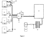
- FIG. 1 illustrates an embodiment of a blending system for producing a chemical composition (e.g., a polishing composition such as a CMP slurry).
- the system includes a plurality of material tanks 12, 14, 16, and 18, a plurality of pumps 13a, 13b, 13c, and 13d, a plurality of mass flow controllers 15a, 15b, 15c, 15d, and 15e, a mixing tank 20, an optional holding tank 21, an optional filter apparatus 22, a packaging station 24a or 24b, an optional load cell 25, and optional recirculation loops 26 and 28, and an optional switch valve 27.
- the blending system can be operated to combine the components of a polishing composition in a continuous flow process with reduced product variations, high throughput, and low product waste.
- all the raw materials e.g. components of the CMP slurry
- can be "stabilized” e.g., by obtaining a material flow having a substantially constant flow rate
- the substantially constant flow rates of the material flows exiting material tanks 12, 14, 16, and 18 can be different from one another.
- the stabilizing is done by recirculating the raw materials back to their respective material tanks through one or more fluid flow controller units (e.g., mass flow controllers).
- material tank 12 includes a recirculation loop 28, which includes a switch valve 27 and a mass flow controller 15e.
- recirculation loop 28 can include two or more mass flow controllers 15e.
- the material in material tank 12 can go through the recirculation loop 28 by opening switch valve 27 and closing a switch valve (not shown in FIG. 1 ) between material tank 12 and mixing tank 20. Once a predetermined amount is reached (as measured by mass flow controller 15a or 15e), switch valve 27 is closed and the switch valve between material tank 12 and mixing tank 20 is open so that the material in material tank 12 can be delivered to mixing tank 20.
- FIG. 1 shows that only one material tank (i.e., material tank 12) has a recirculation loop 28, other material tanks (i.e., material tanks 14, 16, and 18) can each have a recirculation loop This novel and important step reduces the variations in the mixing tank and helps establish an in-process steady state for the ACP process.
- continuous flow includes a bulk flow that is continuous in a downstream direction (e.g., a net flow rate that varies by less than about fifteen percent during steady-state operation) and/or substantially continuous in a downstream direction (e.g., a regularly pulsing flow with net movement in a downstream direction during steady-state operation).
- the ACP system and process described in this disclosure are designed to achieve an in-process steady state.
- mass input and mass output during the process run are substantially equalized.
- Mass input includes the sum of the amounts of all of the raw materials going into the mixing tank.
- Mass output includes the amount of the fully mixed slurry product exiting the mixing tank, which enters the optional holding tank, the optional filter apparatus, or the packaging station.
- the raw material continuous flows and the downstream composition flows are in in-process steady state.
- the final composition is packaged at a steady pre-targeted rate without interruption (e.g., while the mixing tank recirculation and in line quality control measurements are being done).
- material tanks 12, 14, 16, and 18 can be any suitable tank and are configured to receive a material to form a chemical composition.
- a material tank can include an inlet for receiving one or more of the components to be used to form the chemical composition.
- a material tank can include an outlet for transferring the components to mixing tank 20.
- a material tank can have an opening that serves as both the inlet and the outlet.
- a material tank can be the tank used by a manufacturer for supplying a component.
- each material tank 12, 14, 16, and 18 can receive one or more of the following materials: a diluent, an acid, a base, and an abrasive particle composition (e.g., an abrasive particle dispersion) containing abrasive particles.
- a diluent e.g., an acid, a base
- an abrasive particle composition e.g., an abrasive particle dispersion
- each material tank 12, 14, 16, or 18 can optionally receive one or more of the following additional materials: corrosion inhibitors (e.g., benzotriazoles, triazoles, and azoles), oxidizers (e.g., hydrogen peroxide, ammonium persulfate, silver nitrate, ferric nitrates or chlorides, per acids or salts, ozone water, potassium ferricyanide, potassium dichromate, potassium iodate, potassium bromate, vanadium trioxide, hypochlorous acid, sodium hypochlorite, potassium hypochlorite, calcium hypochlorite, magnesium hypochlorite, ferric nitrate, KMgO 4 , other inorganic or organic peroxides, or mixtures thereof), complexing agents, biocides, pH adjusters, and surfactants (e.g., cationic surfactants, anionic surfactants, nonionic surfactants, and amphoteric surfactants).
- corrosion inhibitors e.g., benzotri
- a single raw material can be introduced through more than one of material tanks 12, 14, 16, and 18 (e.g., to improve mixing quality).
- any number e.g., two, three, or four
- material tanks 12, 14, 16, and 18 can be used to introduce the components to mixing tank 20.
- only two material tanks 12 and 14 can be used in the system shown in FIG. 1 .
- the diluent, the acid, and the base can be pre-mixed and the mixture can be introduced through material tank 12, while the abrasive particle composition can be introduced through material tank 14.
- more than four (e.g., five, six, seven or more) material tanks can be used in the system shown in FIG. 1 to introduce the components to mixing tank 20.
- each pump 13a,b,c,d is disposed between and in fluid communication with a respective material tank 12, 14, 16, and 18 and a respective mass flow controller 15a,b,c,d.
- Each pump 13a,b,c,d is configured to move (e.g., continuously) a raw material from a respective material tank 12, 14, 16, and 18 through a respective mass flow controller 15a,b,c,d to mixing tank 20.
- pumps 13a,b,c,d can be electro-mechanical diaphragm pumps including a sealed diaphragm with one side in fluid communication with the working fluid and the other side in communication with a motor drive. Fluid is pumped as the motor drive flexes the diaphragm.
- the system can include a load cell in contact with each of material tanks 12, 14, 16, and 18, such that the load cell is configured to measure the content weight in the material tank.
- each of load cells 25a, 25b, 25c, and 25d can be disposed beneath a material tank (i.e., tank 12, 14, 16, or 18) to measure its content weight.
- each load cell can monitor the content weight in a material tank and can ensure that each of material tanks 12, 14, 16, and 18 has enough material to be transferred to mixing tank 20.
- the load cell can be a hydraulic load cells, a pneumatic load cell, or a strain gauge load cell.
- each pump 13a,b,c,d is in fluid communication with each material tank 12, 14, 16, and 18 and can draw the respective materials from the material tanks 12, 14, 16, and 18 continuously.
- the speed of each pump 13a,b,c,d can be adjusted (e.g., individually adjusted) to change the volume flow rate of a material moving through the respective pump 13a,b,c,d.
- the speed of each pump 13a,b,c,d can be adjusted to adjust the Reynolds number of the combined flow of the continuous material flows (e.g., flows including the diluent, the acid, the base, and/or the abrasive particle composition) in mixing tank 20.
- each mass flow controller 15a,b,c,d can include an adjustable orifice and an internal regulating valve that maintains a constant pressure drop across the orifice to achieve a constant mass flow rate.
- the mass flow rates through the flow controllers 15a,b,c,d can be independently adjustable such that the raw materials can be combined in desired proportions.
- the mass flow rates through the flow controllers 15a,b,c,d can be adjusted to achieve a target concentration of abrasive particles dispersed within the polishing composition.
- the mass flow rates through the flow controllers 15a,b,c,d can be adjusted to adjust the Reynolds number of the combined continuous material flow in mixing tank 20.
- each material tank 12, 14, 16, and 18 can receive one or more of the following materials: a diluent, an acid, a base, and an abrasive particle composition.
- the diluent can include, for example, deionized water.
- the deionized water reduces ionic activity leading to the formation of salts and/or otherwise resulting in particle agglomeration.
- the addition of the diluent through one or more of the material tanks 12, 14, 16, and 18 can facilitate the use of concentrated acid, base, and/or abrasive particle compositions, which are generally less expensive to transport than the corresponding dilute compositions.
- the acid can include, for example, an organic acid (e.g., a carboxylic acid or a sulfonic acid), an inorganic acid (e.g., hydrochloric acid, nitric acid, or sulfuric acid), or a mixture thereof.
- the acid can include a carboxylic acid (e.g., citric acid, succinic acid, acetic acid, propionic acid, or oxalic acid), hydrochloric acid, sulfuric acid, nitric acid or a mixture thereof.
- the acid introduced through one or more material tanks 12, 14, 16, and 18 can have an initial acid concentration of at least about 15% by weight and can be diluted in the continuous fluid process described herein such that the acid has a concentration of less than about 10% by weight (e.g., less than about 1% by weight) in the polishing composition.
- the base can include, for example, potassium hydroxide, ammonium hydroxide, quaternary ammonium compounds (e.g., tetramethyl ammonium hydroxide or tetrabutyl ammonium hydroxide), monoethanol amine, diethanol amine, triethanol amine, or a mixture thereof.
- the base can be introduced through one or more of material tanks 12, 14, 16, and 18 in an initial concentrated solution of at least about 15% by weight and can be diluted in the continuous fluid process described herein such that the base has a concentration of less than about 10% by weight (e.g., less than about 1% by volume) in the polishing composition.
- the abrasive particle composition can include, for example, a water dispersion of silica, ceria, titania, alumina, or a mixture thereof.
- An example of an abrasive particle composition is colloidal silica.
- the abrasive particle composition can include at least about 30 wt% (e.g., at least about 35 wt% or at least about 40 wt%) and/or at most about 50 wt% (e.g., at most about 45 wt% or at most about 40 wt%) of the abrasive particle (e.g., silica).
- the polishing composition prepared from the abrasive particle compositions can include at most about 15 wt% (e.g., at most about 12 wt%, at most about 10 wt%, or at most about 8 wt%) and/or at least about 1 wt% (e.g., at least about 3 wt%, at least about 5 wt%, or at least about 7 wt%) of the abrasive particle (e.g., silica).
- the abrasive particle e.g., silica
- the polishing composition can further include one or more salts.
- the salts can be neutral, basic, or acidic in nature.
- the salts can be formed from the acid and base added into the polishing composition.
- the salts can be added into the polishing composition independent of the acid and base described above.
- Exemplary salts that can be included in the polishing composition include carboxylate salts, sulfate salts, nitrate salts, halide salts, and phosphate salts, such as those formed with potassium or ammonium cation.
- the salts can include potassium citrate, potassium carbonate, potassium nitrate, potassium sulfate, potassium chloride, ammonium nitrate, ammonium sulfate, ammonium citrate, ammonium oxalate.
- the polishing composition thus formed can have a pH ranging from at least about 2 (e.g., at least about 3, at least about 4, or at least about 5) to at most about 11 (e.g., at most about 10, at most about 9, or at most about 8).
- material tanks 12, 14, 16, and 18 can receive one or more of deionized water, potassium hydroxide, citric acid, and a colloidal silica dispersion having a pH of 7, which are combined, according to methods described below, into a polishing composition having a final pH of about 10.2.
- the blending system can include a mixing tank 20 in which the materials from material tanks 12, 14, 16, and 18 are mixed to form a colloid dispersion.
- Mixing tank 20 is generally in fluid communication with the material tanks 12, 14, 16, and 18 (e.g., through mass flow controllers 15a,b,c,d).
- mixing tank 20 is configured to continuously receive the materials from material tanks 12, 14, 16, and 18 to form a polishing composition and continuously deliver the polishing composition downstream (e.g., to packaging station 24a or 24b).
- the blending system described herein can include two or more (e.g., three or four) mixing tank 20.
- mixing tank 20 can have one or more inlets for receiving materials from material tanks 12, 14, 16, and 18 and at least one outlet for delivering the mixed polishing composition downstream.
- mixing tank 20 does not include any mixing device, such as a stirrer (e.g., a mechanic or electrical stirrer) or a baffle, in the tank.
- the continuous material flows from material tanks 12, 14, 16, and 18 can create a turbulent flow when they are introduced into mixing tank 20 and are mixed by this turbulent flow.
- the "turbulent flow” is a flow that has a Reynolds numbers above about 4000. Without wishing to be bound by theory, it is believed that a turbulent flow of the materials in mixing tank 20 can facilitate formation of a stable polishing composition.
- mixing tank 20 may include a mixing device, such as a stirrer (e.g., a mechanic or electrical stirrer) or a baffle, in the tank.
- a mixing device such as a stirrer (e.g., a mechanic or electrical stirrer) or a baffle, in the tank.
- FIG. 4 shows an embodiment of a blending system that includes a mixing device 17.
- mixing tank 20 can include a recirculation loop 26 that is in fluid communication with mixing tank 20 and facilitates the mixing in the tank.
- Recirculation loop 26 can include a pipe that connects between an outlet and an inlet on mixing tank 20 such that the liquid composition in mixing tank 20 can flow out of tank 20 and back into tank 20 through recirculation loop 26.
- recirculation loop 26 can include a pump (not shown in FIG. 1 ) that controls the flow rate of the liquid stream in recirculation loop 26.
- the pump can shut off recirculation loop 26 so that the loop is no longer in use.
- recirculation loop 26 can include one or more in-line mixers (e.g., static or dynamic mixers).
- the recirculation of the chemical composition in mixing tank 20 continues throughout the ACP process (i.e., without interrupting the ACP process) to ensure thorough mixing.
- mixing tank 20 has a volume of from at least about 10 liters (e.g., at least about 20 liters, at least about 40 liters, at least about 50 liters, at least about 80 liters, at least about 100 liters, at least about 200 liters, at least about 500 liters, or at least about 1000 liters) to at most about 1500 liters (e.g., at most about 1200 liters, at most about 1000 liters, at most about 750 liters, at most about 500 liters, at most about 400 liters, or at most about 250 liters).
- at least about 10 liters e.g., at least about 20 liters, at least about 40 liters, at least about 50 liters, at least about 80 liters, at least about 100 liters, at least about 200 liters, at least about 500 liters, or at least about 1000 liters
- at most about 1500 liters e.g., at most about 1200 liters
- the volume of mixing tank 20 can be generally larger than the volume of an in-line mixer (e.g., a static mixer or a dynamic mixer) typically used in a conventional continuous process such that mixing tank 20 allows the components of a polishing composition (e.g., a CMP slurry) to be combined and mixed concurrently.
- the lower limit on the tank volume can be decided by the amounts and flow rates of the raw materials. For example, a small mix tank volume (e.g., 10 liters) may be enough if only 2 chemicals are going into mixing tank 20 at low flow rates.
- the volume of mixing tank 20 can be generally smaller than the volume of a tank typically used in a conventional batch process, thereby reducing the manufacturing costs and environmental impact of the process.
- the materials from material tanks 12, 14, 16, and 18 can be continuously transferred into mixing tank 20 substantially at the same time, in which the materials are combined and mixed to form a chemical composition (e.g., a polishing composition).
- the chemical composition thus formed can be continuously moved downstream (e.g., to a filter apparatus or a package station).
- the amount of at least one component e.g., the amounts of two, three, or all components
- the amount of at least one component e.g., the amounts of two, three, or all components
- mixing tank 20 can be measured (e.g., by using a HPLC, LC-MS, or ICP-OES, all of which are available at Thermo Fisher Scientific, Waltham, MA) in a quality control step 19 to determine if it is within a predetermined range for that component.
- the continuous process can continue without modification. If the amount of the component is outside of the predetermined range, the amount of the component can be adjusted (e.g., by adjusting one of mass flow controllers 15a,b,c,d) such that it falls within the predetermined range.
- other quality-related parameters can also be measured using a sample from the mixing tank. These parameters include, but are not limited to, pH, conductivity, density, and mean particle size. Based on these measurements, further adjustments to material flows can be performed, if necessary. In some embodiments, such an in-process quality control measurement of the chemical composition in mixing tank 20 can be performed without interrupting the continuous process.
- such an in-process quality control measurement can be performed by using at least one quality determination unit that is attached integrally to mixing tank 20.
- quality determination units include a pH meter, a conductivity meter, a concentration meter, and a LPC (Large Particle Count) meter.
- Such quality determination units can be attached integrally to other system components (such as a material tank, a hold tank, a filtering apparatus, or a connecting pipe) to perform in-process quality control measurements.
- mixing tank 20 in a continuous process can result in reduced product variations and reduced product waste compared to a conventional continuous process (such as a continuous process in which the components of a polishing composition are mixed one by one sequentially using an in-line mixer (e.g., an in-line static or dynamic mixer) between material tanks and a holding tank) or a conventional batch process.
- a conventional continuous process such as a continuous process in which the components of a polishing composition are mixed one by one sequentially using an in-line mixer (e.g., an in-line static or dynamic mixer) between material tanks and a holding tank) or a conventional batch process.
- an in-line mixer e.g., an in-line static or dynamic mixer
- a total lot-to-lot variation or a total within lot variation of at most about 1% (e.g., at most about 0.9%, at most about 0.8%, at most about 0.7%, at most about 0.6%, at most about 0.5%, at most about 0.4%, at most about 0.3%, at most about 0.2%, or at most about 0.1%) in the weight of a component (e.g., each component) and/or a quality-related parameter (e.g., pH, conductivity, density, and mean particle size).
- a component e.g., each component
- a quality-related parameter e.g., pH, conductivity, density, and mean particle size
- lot-to-lot variation refers to the variations in a parameter of the final product between different lots (e.g., average variations from one lot to another lot).
- the term "within lot variation” refers to the variations in a parameter of the final product within a particular lot (e.g., average variations from one package to another package).
- total variation refers to the difference between the highest variation and the lowest variation for a given parameter.
- the polishing composition thus prepared can have a total lot-to-lot variation of at most about 0.5% in the weight of at least one component or in at least one quality-related parameter (e.g., pH, conductivity, density, and mean particle size).
- the systems and methods used in a conventional continuous process or a conventional batch process typically produce a product having a total lot-to-lot variation significantly higher than 0.5% in the weight of a component or a quality-related parameter (e.g., pH, conductivity, density, and mean particle size).
- a quality-related parameter e.g., pH, conductivity, density, and mean particle size
- the blending systems described herein do not include an in-line mixer (such as a static or dynamic mixer) between material tanks 12, 14, 16, and 18 and mixing tank 20.
- An in-line mixer typically includes a mixing device (e.g., a baffle), has only one inlet and one outlet, and has a small volume (e.g., at most about 10 liters).
- a mixing device e.g., a baffle
- Such an in-line mixer typically is not designed to mix three or more components at the same time and therefore is significantly different from mixing tank 20 (which can mix three or more components at the same time).
- the systems described herein can include one or more in-line mixers at locations other than between material tanks 12, 14, 16, and 18 and mixing tank 20, such as in optional recirculation loop 26 or 28.
- the blending system shown in FIG. 1 can include an optional filter apparatus 22.
- the system when manufacturing a polishing composition (e.g., a CMP slurry), the system can include filter apparatus 22 to filter the polishing composition exiting mixing tank 20 to remove agglomerated particles or impurities. Details of the filters that can be used as filter apparatus 22 are provided, for example, in U.S. Patent Application No. 12/702,602 , titled "Fluid Processing," filed on February 9, 2010, and published as U.S. Patent Application Pub. 2010/0320127 A1 , the entire contents of which are incorporated herein by reference.
- the filter apparatus can be either Depth/ Profile filters with various pore ratings or Membrane filters.
- the filtration media for Depth filters are typically made from polypropylene, whereas the filtration media for Membrane filters are typically made from Nylon.
- the filters can be purchased from commercial sources, such as Pall Corporation (Port Washington, NY), Entegris Inc. (Billerica, MA), and Roki America Co. Ltd. (Findlay, OH).
- an optional quality control step 23 can be performed to analyze the contents of the filtered polishing composition (e.g., to determine whether the amount of a component in the filtered polishing composition is within a predetermined range). If the filtered polishing composition meets the targeted specification, it can then flow to packaging station 24a or 24b. In some embodiments, at packaging station 24a or 24b, the polishing composition can be either used directly (e.g., in a CMP process to smooth wafers) or packaged for future use (e.g., at another location).
- filter apparatus 22 can be omitted or can be membrane type (absolute) filters which are much finer and suited for filtration of fine chemical formulations.
- the blending system described in FIG. 1 can include at least one (e.g., two, three, or more) optional holding tank 21.
- Holding tank 21 can be disposed between mixing tank 20 and optional filter apparatus 22, and in fluid communication with mixing tank 20 and filter apparatus 22.
- holding tank 21 can be configured to continuously receive the polishing composition from mixing tank 20.
- holding tank 21 can have a relatively large volume ranging from at least about 1,500 liters (e.g., at least about 2,000 liters, at least about 4,000 liters, at least about 5,000 liters, at least about 6,000 liters, at least about 8,000 liters, or at least about 10,000 liters) to at most about 20,000 liters (e.g., at most about 18,000 liters, at most about 16,000 liters, at most about 15,000 liters, at most about 14,000 liters or at most about 12,000 liters).
- holding tank 21 can be used as a storage tank to store the polishing composition formed in mixing tank 20.
- holding tank 21 can be used to control the quality of the polishing composition formed in mixing tank 20. For example, if it is unclear whether the polishing composition formed in mixing tank 20 meets the targeted specification, the polishing composition can be first moved to holding tank 21 where its contents are measured. Once it is confirmed that the polishing composition in holding tank 21 meets the targeted specification, the dispersion can be transferred to filter apparatus 22 and/or packaging station 24.
- the system shown in FIG. 1 can include an optional pump between mixing tank 20 and optional holding tank 21, between optional holding tank 21 and optional filter apparatus 22, and/or between optional filter apparatus 22 and packaging station 24.
- a pump can be in fluid communication with these components to facilitate transfer of a fluid between these components and to control the volume flow rate of the fluid.
- the system shown in FIG. 1 can include an optional mass flow controller between mixing tank 20 and optional holding tank 21, between optional holding tank 21 and optional filter apparatus 22, and/or between optional filter apparatus 22 and packaging station 24.
- a mass flow controller can be in fluid communication with these components to facilitate transfer of a fluid between these components and to control the mass flow rate of the fluid.
- FIG. 4 illustrates another embodiment of a blending system for producing a chemical composition.
- the system includes a plurality of material tanks 12, 14, 16, and 18, a plurality of pumps 13a, 13b, 13c, and 13d, a plurality of mass flow controllers 15a, 15b, 15c, and 15d, a mixing tank 20, a mixing device 17 attached to mixing tank 20, an optional holding tank 21, an optional filter apparatus 22, a packaging station 24, and an optional recirculation loop 26.
- Each of material tank 12, 14, 16, and 18 includes a load cell located (not labelled) beneath the tank.
- the system shown in FIG. 1 has been described for the manufacturing of a polishing composition, the system can also be used to manufacturing chemical compositions other than polishing compositions, such as developers, etching compositions and cleaning compositions.
- One difference between the polishing composition and the other chemical compositions is that the polishing composition has particles, whereas the other chemical compositions may not have any particles.
- the raw material feeds in material tanks 12, 14, 16, and 18 can include acids, bases, and diluents without the particle raw material feed.
- This disclosure also features continuous methods of forming a chemical composition (e.g., a polishing composition such as a CMP slurry).
- the methods can include at least the following two steps: (1) mixing a plurality of continuous material flows in at least one mixing tank to form a chemical composition, each continuous material flow containing at least one component of the chemical composition; and (2) moving a continuous flow of the chemical composition to a packaging station downstream of the mixing tank.
- the mixing and moving steps can be performed continuously.
- the material and chemical composition flows are in an in-process steady state such that there is a mass balance for the process during the continuous operation.
- the mixing process in the at least one mixing tank includes at least one mixing method selected from the group consisting of turbulent mixing of the material flows, mechanical agitation of the material flows, recirculation of the chemical composition, and a combination thereof.
- the methods described herein can further include providing a plurality of material tanks, each of which contains at least one component of a chemical composition and moving (e.g., continuously) a plurality of continuous material flows from the material tanks to the mixing tank.
- the methods described herein can further include obtaining a material flow having a substantially constant flow rate (e.g., mass flow rate) prior to the mixing process in the mixing tank. For example, this can be achieved by continuous recirculation of the material flow in a material tank through at least one fluid transfer unit and at least one flow control unit until a predetermined flow rate is reached.
- the methods described herein can further include performing an in-process quality control measurement of the chemical composition in the mixing tank without interrupting the continuous process.
- the methods described herein can include a measuring step that measures the amount of at least one component (e.g., each component) in the mixing tank to determine whether the amount is within a predetermined range.
- the measuring step can be performed without stopping the mixing step (e.g., mixing components in the mixing tank to form a chemical composition) and/or the moving step (e.g., moving a continuous flow of the chemical composition to a packaging station). If the amount measured is outside the predetermined range, the amount of that component in the mixing tank can be adjusted by allowing more or less of that component to be added into the mixing tank.
- the methods described herein can further include at least one step (e.g., two or three steps) selected from the group consisting of measuring a mass flow rate of each continuous material flow (e.g., by using a mass flow controller), measuring the volume flow rate of each continuous material flow (e.g., by using a pump), and measuring a content weight in a tank that supplies a continuous material flow containing at least one component (e.g., by using a load cell).
- a mass flow rate of each continuous material flow e.g., by using a mass flow controller
- measuring the volume flow rate of each continuous material flow e.g., by using a pump
- measuring a content weight in a tank that supplies a continuous material flow containing at least one component e.g., by using a load cell
- the continuous flow of the chemical composition exiting the mixing tank can have a relatively high volume flow rate, such as at least about 20 liters per minute (e.g., at least about 30 liters per minute, at least about 40 liters per minute, at least about 50 liters per minute, or at least about 60 liters per minute) and/or at most about 1,000 liters per minute (e.g., at most about 500 liters per minute, at most about 100 liters per minute, at most about 90 liters per minute, at most about 80 liters per minute, at most about 70 liters per minute, or at most about 60 liters per minute).
- the ACP methods described herein can have a relatively high throughput, thereby significantly increasing manufacturing efficiency and reducing manufacturing costs.
- the methods described herein can include moving a continuous flow of the chemical composition to an optional holding tank (e.g., to ensure that the chemical composition exiting the mixing tank meets the predetermined specifi cati on).
- the methods described herein before moving a continuous flow of the chemical composition to a packaging station, can include an optional filtering step that includes (1) moving a continuous flow of the chemical composition to a filter apparatus and (2) filtering the chemical composition exiting from the mixing tank (e.g., to remove agglomerated particles or impurities).
- the filtered chemical composition can then be moved the package station, in which the chemical composition can be used directly or packaged into a product for future uses.
- the methods described herein do not include a filtering step, the chemical composition exiting the mixing tank can be transferred to the packaging station directly.
- At least two (e.g., three, four, five, or all) of the following sub-steps in the methods described herein can be performed continuously: (1) moving the plurality of continuous material flows from the material tanks to the mixing tank, (2) mixing the plurality of continuous material flows in the mixing tank to form a chemical composition, (3) moving a continuous flow of the chemical composition to an optional holding tank, (4) moving a continuous flow of the chemical composition to an optional filter apparatus, (5) optionally filtering the chemical composition, and (6) moving the chemical composition (e.g., a filtered chemical composition) to a packaging station.
- the ACP methods described herein can be performed by using the system illustrated in FIG. 1 .
- the ACP methods described herein can include providing a plurality of material tanks 12, 14, 16, and 18, each of which contains at least one component of a chemical composition (e.g., a polishing composition such as a CMP slurry).
- a plurality of continuous material flows (each containing at least one component of the chemical composition) can then be moved from material tanks 12, 14, 16, and 18 to mixing tank 20 by using pumps 13a,b,c,d. Before moving the continuous material flows to mixing tank 20, all the raw materials (e.g.
- components of the CMP slurry can go through a recirculation loop (e.g., loop 28) to obtain a substantially constant flow rate at a desired value.
- a recirculation loop e.g., loop 28
- the components can be combined and mixed continuously to form a chemical composition.
- the mass flow rates of the plurality of continuous material flows can be measured and adjusted continuously by using mass flow controllers 15a,b,c,d to ensure that appropriate amounts of components are added to mixing tank 20 to form the desired chemical composition.
- the volume flow rate of each continuous material flow and the content weight in each material tank 12, 14, 16, and 18 can also be measured and monitored to ensure the formation of the desired chemical composition.
- a quality control step 19 can then be performed to measure the amount of at least one component (e.g., two, three, or all components) in mixing tank 20 to determine whether the amount is within a predetermined range.
- This step can be performed without interrupting the continuous method, such as stopping the other continuous steps (e.g., the mixing step or the step of moving a continuous flow of a chemical composition downstream) in the continuous methods.
- the continuous flow of the chemical composition formed in mixing tank 20 can be moved to filter apparatus 22 to filter the chemical composition.
- the filtered chemical composition can then be moved to packaging station 24 where the chemical composition can be used directly or packaged into a product for future use.
- an optional quality control step 23 can be performed to analyze the contents of the chemical composition (e.g., to determine whether the amount of a component in the chemical composition is within a predetermined range). If the chemical composition meets the targeted specification, it can then flow to packaging station 24.
- the continuous method can include moving the continuous flow of the chemical composition from mixing tank 20 to holding tank 21 and from holding tank 21 to filter apparatus 22.
- pumps are described in connection with the systems shown in FIGs. 1 and 4
- other fluid transfer units such as gravitational feed units, pressurized tanks, or siphon feed units
- gravitational feed units such as gravitational feed units, pressurized tanks, or siphon feed units
- siphon feed units can also be used in the blending systems described in this disclosure.
- mass flow controllers are described in connection with the systems shown in FIGs. 1 and 4
- other fluid flow controller units such as volume flow controllers
- volume flow controllers can also be used in the blending systems described in this disclosure.
- the polishing composition contained chemicals, water and silica abrasive particles.
- the chemicals included a carboxylic acid (Acid 2), an organic base (Base 2), and other chemicals.
- Acid 2 carboxylic acid
- Base 2 organic base
- FIG. 2 for each lot, the above chemicals and water were pumped from materials tank 12, 13, and 16 into a 3000 gallon tank 20 (which serves both as a mixing tank and a holding tank) one by one through pumps 13a,b,c and mass flow controllers 15a,b,c.
- the silica abrasive dispersion was then pumped from material tank 18 into the tank 20 through pump 13d and mass flow controller 15d.
- Tank 20 contained a paddle type mixer 17, which was activated to mix all the components.
- the mixed polishing composition from the tank was pumped through a filter apparatus 20 (which contained several filter banks) into a packaging station 24 (which included drums or totes) that hold the finished product. Quality control was performed on the packaged polishing composition.
- the production throughput was measured by dividing the number of gallons packaged by the total time used to make that particular lot of polishing composition. The total time included the time to introduce all the chemicals, water and abrasive dispersion, the mixing time, and the filtration and packaging time.
- the normalized throughput data are summarized in FIG. 5 .
- polishing composition 100 lots were made using a continuous static mixer blending process.
- the polishing composition is similar to the polish composition made from the Batch process except that it contained Acid 1 and Base 1 (instead of Acid 2 and Base 2).
- raw materials such as chemicals, water, and abrasive dispersion were mixed using a number of in-line static mixers. This was done sequentially as follows: As illustrated in FIG. 3 , raw material 1 and raw material 2 were pumped from material tanks 12 and 14 into the first in-line static mixer 17a through pumps 13a,b and mass flow controller 15a,b. This mixture in mixer 17a and raw material 3 from material tank 16 were then pumped into the second in-line static mixer 17b.
- This mixture in mixer 17b and raw material 4 from material tank 18 were then pumped into the third in-line static mixer 17c.
- Materials 3 and 4 were pumped into in-liner mixers 17b,c by using pumps 13c,d and mass flow controllers 15c,d.
- This continuous flow process continued until all the raw materials were mixed.
- the mixture thus obtained was introduced into a holding tank 21.
- a quick quality control step 19of selected parameters e.g., conductivity
- the continuous process continued until a certain number of drums or totes where filled.
- the production throughput was measured by dividing the number of gallons packaged by the total time of production.
- the normalized throughput data are summarized in FIG. 5 .
- the production throughput for the ACP process was measured by dividing the number of gallons packaged by the production time.
- the normalized throughput in gallons per unit time for the Batch, Continuous and ACP processes is shown in FIG. 5 .
- the Continuous process had a throughput of 293 gallons per minute and the ACP process has a throughput of 356 gallons per minute.
- the ACP process had a throughput of about 3.5 times the throughput of the Batch process and about 1.2 times the throughput of the Continuous process.
- FIG. 5 clearly demonstrate that the ACP process described in this disclosure had a significantly larger throughput than the comparative Batch and Continuous processes, which would result in substantial cost-savings.
- each component in a composition has a particular electron mobility.
- This electron mobility of the individual components is measured by conductivity.
- the overall conductivity of the composition is a sum of the individual conductivities of the components. As such, if the conductivity is consistent for multiple production lots, it suggests that there are minimal process variations and the quality of the end product is considered good. Thus, conductivity "variation" of the composition can be a key indicator of the overall product quality and production process consistency.
- this example further confirms the superiority of the ACP process over the two comparative processes.
Landscapes
- Chemical & Material Sciences (AREA)
- Chemical Kinetics & Catalysis (AREA)
- Engineering & Computer Science (AREA)
- Mechanical Engineering (AREA)
- Dispersion Chemistry (AREA)
- Organic Chemistry (AREA)
- Physics & Mathematics (AREA)
- Fluid Mechanics (AREA)
- Grinding-Machine Dressing And Accessory Apparatuses (AREA)
- Finish Polishing, Edge Sharpening, And Grinding By Specific Grinding Devices (AREA)
- Mechanical Treatment Of Semiconductor (AREA)
- Materials Engineering (AREA)
- Accessories For Mixers (AREA)
- Detergent Compositions (AREA)
- Materials For Photolithography (AREA)
- Measuring Volume Flow (AREA)
- Mixers With Rotating Receptacles And Mixers With Vibration Mechanisms (AREA)
Abstract
This disclosure features methods of forming chemical compositions. The method includes (1) mixing a plurality of continuous material flows in a mixing tank to form a chemical composition, each continuous material flow including at least one component of the composition; and (2) moving a continuous flow of the chemical composition to a packaging station downstream of the mixing tank. The mixing and moving steps are performed continuously. This disclosure also features systems that can be used to perform such methods.
Description
- The present application claims priority to
U.S. Provisional Application Serial No. 62/306,795, filed on March 11, 2016 - This disclosure relates to methods of continuous fluid processing, as well as related systems and components.
- Mixing is a process in which two or more substances are combined while the chemical properties of each substance remain largely unchanged. The properties of the overall mixture, however, can differ from those of the component substances. Thus, mixing is often used to produce a medium with a desired set of physical and chemical properties which can be confirmed by analytical techniques.
- For example, in semiconductor fabrication, chemical mechanical planarization/ polishing (CMP) is used to make wafer surfaces flat. This process requires use of a slurry containing abrasive particles dispersed in a liquid chemical composition (such as those containing an acid and/or a base). The CMP slurry is typically manufactured by mixing various chemicals and abrasive particles to form a dispersion (e.g., a colloidal dispersion). During CMP, movement of the abrasive particles on the wafer mechanically removes material from the wafer surface. The acid or base in the slurry facilitates the chemical removal of material by reacting with the material to be removed. Hence, the process is called "chemical" "mechanical" polishing. To produce CMP slurries having desired properties, it can be useful to filter the CMP slurries to achieve the desired distribution of abrasive particles dispersed within the chemically reactive agents. The filtration also ensures that the end CMP product has high purity.
- As the semiconductor wafers become more advanced, the features on the wafer surfaces become finer and more complex. Planarizing these complex fine features requires very tight polish processing windows. Hence the CMP process requires that the CMP slurry property specifications are very tight. This, in turn, is forcing the CMP slurry manufacturers to significantly improve their production process capability while reducing variations between lots. The conventional slurry production processes are unable to meet these stringent demands.
- Conventional slurry manufacturing processes include a Batch process (
FIG. 2 ) and a Continuous Process (FIG. 3 ). In a batch process, all the slurry components are added to a large tank one by one (usually by a fluid transfer unit such as a pump, and/or a flow controller unit), followed by mixing the components by an agitator type device and a QC (quality control) step. After that, the mixed slurry is sent to packaging station usually through a filter station. The batch process suffers from many drawbacks including a large environmental footprint, long addition and mixing times, high property variations, low throughput, and high production costs. - A conventional continuous process (
FIG. 3 ), on the other hand, replaces the very large tanks in the batch process with smaller tanks, and introduces in-line static or dynamic mixers. The raw materials are fed into these in-line mixers one by one (but never all together in one mixer). This design allows the process to be continuous and increases the throughput. However, the in-line mixers are small and create high back pressures. Each raw material flow component loop going to the in-line mixer creates flow control issues causing significant property variations. Thus, the continuous process cannot meet the tight specification demands either. - This disclosure describes an Advanced Continuous Process and related system that addresses these shortcomings.
- This disclosure is based on the unexpected discovery that using a tank (e.g., a relatively small tank) in which materials (e.g., materials for producing a CMP slurry) are concurrently received and mixed in a continuous fluid process can result in reduced product variations and reduced product waste, thereby significantly increasing manufacturing efficiency, manufacturing yields, and product consistency, and reducing manufacturing costs (e.g., for producing a CMP slurry).
- In one aspect, this disclosure features a method of forming a chemical composition (e.g., a polishing composition such as a CMP slurry). The method includes A) mixing a plurality of continuous material flows in at least one mixing tank to form a chemical composition, each continuous material flow comprising at least one component of the chemical composition; and B) moving a continuous flow of the chemical composition to a packaging station downstream of the at least one mixing tank. The mixing and moving steps are performed continuously, the material and chemical composition flows are in an in-process steady state; and the mixing process in the at least one mixing tank includes at least one mixing method selected from the group consisting of turbulent mixing of the material flows, mechanical agitation of the material flows, recirculation of the chemical composition, and a combination thereof.
- In another aspect, this disclosure features a system that includes (1) a plurality of material tanks, each material tank being configured to receive a material used to form a chemical composition (e.g., a polishing composition such as a CMP slurry); (2) at least one mixing tank in which the materials from the material tanks are mixed to form a chemical composition, wherein the mixing tank is in fluid communication with the plurality of material tanks, the mixing tank is configured to continuously receive the materials from the material tanks and to continuously deliver the chemical composition downstream, and the mixing tank optionally includes a recirculation loop in fluid communication with the mixing tank; (3) optionally, at least one holding tank downstream from the mixing tank and in fluid communication with the mixing tank; and (4) optionally, at least one filter apparatus in fluid communication with the mixing tank, the filter apparatus being configured to receive and filter the chemical composition. The system does not include an in-line static or dynamic mixer between each material tank and the mixing tank.
- Embodiments can include one or more of the following features:
In some embodiments, the method further includes obtaining a material flow having a substantially constant flow rate prior to the mixing step. In such embodiments, obtaining a material flow having a substantially constant flow rate includes continuous recirculation of the material flow in a material tank through at least one fluid transfer unit and at least one flow control unit until a predetermined flow rate is reached. - In some embodiments, the method further includes performing an in-process quality control measurement of the chemical composition in the mixing tank without interrupting the continuous process.
- In some embodiments, the method further includes measuring the amount of a component in the mixing tank to determine whether the amount is within a predetermined range. In some embodiments, the measuring step is performed without stopping the mixing or moving step.
- In some embodiments, before moving the continuous flow of the chemical composition to the packaging station, the method further includes at least one step selected from the group consisting of measuring a mass flow rate of each continuous material flow, measuring the volume flow rate of each continuous material flow, and measuring a content weight in a tank that supplies a continuous material flow containing at least one component.
- In some embodiments, the mixing tanking does not include a stirrer or a baffle.
- In some embodiments, the mixing tank has a volume of from about 40 liters to about 1,500 liters.
- In some embodiments, the chemical composition is a polishing composition prepared from components including a diluent, an acid, a base, a salt, and abrasive particles.
- In some embodiments, the diluent includes deionized water.
- In some embodiments, the acid includes an organic acid, an inorganic acid, or a mixture thereof.
- In some embodiments, the base includes potassium hydroxide, ammonium hydroxide, quaternary ammonium compounds (e.g., tetramethyl ammonium hydroxide or tetrabutyl ammonium hydroxide), monoethanol amine, diethanol amine, triethanol amine, or a mixture thereof.
- In some embodiments, the salt includes potassium citrate, potassium carbonate, ammonium nitrate, ammonium sulfate, ammonium citrate, ammonium oxalate, potassium nitrate, potassium sulfate, potassium chloride, or a mixture thereof.
- In some embodiments, the abrasive particles include silica (e.g., colloidal silica), ceria, titania, alumina, or a mixture thereof.
- In some embodiments, the continuous flow of the chemical composition includes at most about 50 wt% silica.
- In some embodiments, the continuous flow of the chemical composition has a pH of from about 2 to about 11 (e.g., from about 2 to about 9).
- In some embodiments, the method further includes continuously moving the chemical composition into a holding tank prior to packaging.
- In some embodiments, the method further includes filtering the continuous flow of the chemical composition before moving the continuous flow of the chemical composition to the packaging station.
- In some embodiments, the continuous flow of the chemical composition exiting the mixing tank has a volume flow rate of at least about 20 liters per minute.
- In some embodiments, the method forms a chemical composition having a total lot-to-to variation or a total within lot variation of at most about 1% in the weight of a component.
- In some embodiments, the mixing tank includes at least one mixing system. In such embodiments, the mixing system can include an agitator (e.g., a mechanical agitator), a vortex, a turbulent mixer, a recirculation loop, or a combination thereof.
- In some embodiments, the system further includes at least one quality determination unit that is attached integrally to a system component. In such embodiments, the quality determination unit can include a pH meter, a conductivity meter, a concentration meter, or a LPC (Large Particle Count) meter.
- In some embodiments, the system further includes a fluid transfer unit (e.g., a pump) in fluid communication with each material tank, the fluid transfer unit being configured to continuously transfer the material in each material tank to the mixing tank.
- In some embodiments, the system further includes a fluid flow controller unit (e.g., a mass flow controller) between each material tank and the mixing tank, the fluid flow controller unit being configured to adjust the flow rate (e.g., the mass flow rate) of the material transferred from each material tank to the mixing tank.
- In some embodiments, the system includes a load cell in contact with each material tank, the load cell being configured to measure the content weight in each material tank.
- In some embodiments, the system further includes a holding tank in fluid communication with the mixing tank, the holding tank being configured to continuously receive the chemical composition from the mixing tank.
- In some embodiments, the holding tank has a volume of from about 1,500 liters to about 20,000 liters.
- In some embodiments, the system further includes the filter apparatus.
- In some embodiments, the system further includes a packaging station downstream of the mixing tank, the packaging station being configured to packaging the chemical composition.
- In some embodiments, the system further includes a recirculation loop in fluid communication with the mixing tank, the recirculation loop being configured to recirculate the chemical composition back to the mixing tank.
- In some embodiments, the system further includes a plurality of fluid transfer units, wherein each fluid transfer unit is configured to continuously transfer a material from a system component (e.g., a material tank, a mixing tank, or a holding tank) to another system component (e.g., a mixing tank, a holding tank, or a packaging station).
- In some embodiments, the system further includes at least one heating unit, wherein the heating unit is configured to independently heat a system component (e.g., a material tank, a mixing tank, or a holding tank).
- Other features, objects, and advantages of the subject in this disclosure will be apparent from the description, drawings, and claims.
-
-
FIG. 1 is a schematic view of an embodiment of a blending system described in this disclosure. This blending system is also referred to as the ACP (Advanced Continuous Process) blending system. -
FIG. 2 is a drawing of a conventional batch process. -
FIG. 3 is a drawing of a conventional continuous process. -
FIG. 4 is a drawing of another embodiment of the ACP blending system described in this disclosure. -
FIG. 5 is a bar graph depicting normalized manufacturing throughput for three different manufacturing processes, i.e., a conventional Batch process, a conventional Continuous process (CP), and an ACP process, each of which was obtained based on a 100-lot scale. -
FIG. 6 is a bar graph depicting normalized conductivity lot-to-lot variations (i.e., total and ± variations) obtained from the three different manufacturing processes referred to inFIG. 2 to 4 based on a 100-lot scale. -
FIG. 7 is a bar graph depicting normalized lot-to-lot total variations in base and acid concentrations obtained from the three different manufacturing processes referred to inFIG. 2 to 4 based on a 100-lot scale. - Like reference symbols in the various drawings indicate like elements.
- Semiconductor chemicals, such as the CMP slurries, wet etch formulations and other wet compositions typically should have high quality yet low-cost. The high-quality requirement is necessary to ensure high semiconductor wafer yields. Therefore, semiconductor users demand very tight specifications for the CMP slurries and other wet compositions. In high-volume chemical manufacturing, it is a major challenge to assure very tight specifications, while still keeping the costs down. Conventional batch processes (such as the one shown in
FIG. 2 ) are typically performed in a relatively large holding tank, and do not have mixing and packaging performed continuously. In a typical Batch blending process, the individual raw materials are added to the tank one by one, which takes a very long time. Subsequently, they are usually mixed by an in-situ agitator for a period of time, followed by a quality control (QC) measurement. If the QC measurement is within specification, the blended composition is moved to filtering and packaging. Batch processes occupy a large environmental foot print, take long time, and hence are costly. Conventional continuous processes have mixing and packaging performed continuously, but typically use static in-line mixers between material tanks and a holding tank to mix the material flows. The in line mixers result in pressure drops across them and require bigger pumps to overcome these pressure drops. They can also result in component variations. Both of these conventional processes do not meet the challenges of advanced semiconductor node applications. Surprisingly, the inventors have found that the systems and methods described herein, also referred to as Advanced Continuous Process (ACP), can produce high quality and low cost chemical compositions at a high throughput, to satisfy the advanced semiconductor node applications. - In general, this disclosure relates to methods of continuous fluid processing to form a chemical composition, as well as related systems and components.
- In some embodiments, the chemical composition can be a liquid-based composition (e.g., a composition containing water, one or more organic solvents, or a mixture thereof), such as those used in a semiconductor process. Examples of suitable chemical compositions that can be formed by the methods and systems described herein include polishing compositions (e.g., chemical mechanical planarization (CMP) slurries), developers (e.g., TMAH developers), etching compositions, and cleaning compositions. Examples of polishing compositions that can be prepared by the systems and methods described herein have been described, for example, in
U.S. Application Publication No. 2013-0067998 . Examples of etching compositions that can be prepared by the systems and methods described herein have been described, for example, inU.S. Application Publication Nos. 2015-0267112 and2012-0231632 . Examples of etching compositions that can be prepared by the systems and methods described herein have been described, for example, inU.S. Application Publication Nos. 2015-0159125 ,2015-0159124 , and2015-0111804 . -
FIG. 1 illustrates an embodiment of a blending system for producing a chemical composition (e.g., a polishing composition such as a CMP slurry). As shown inFIG. 1 , the system includes a plurality ofmaterial tanks pumps mass flow controllers tank 20, anoptional holding tank 21, anoptional filter apparatus 22, apackaging station optional recirculation loops optional switch valve 27. As will be described in further detail below, the blending system can be operated to combine the components of a polishing composition in a continuous flow process with reduced product variations, high throughput, and low product waste. - Before the ACP process fully starts by using the blending system shown in
FIG. 1 , all the raw materials (e.g. components of the CMP slurry) can be "stabilized" (e.g., by obtaining a material flow having a substantially constant flow rate) to ensure that the amounts of raw materials going into the mixing tank meet the predetermined amounts. In some embodiments, depending on the desired amount of each component in the final chemical composition, the substantially constant flow rates of the material flows exitingmaterial tanks FIG. 1 ,material tank 12 includes arecirculation loop 28, which includes aswitch valve 27 and amass flow controller 15e. In some embodiments,recirculation loop 28 can include two or moremass flow controllers 15e. - Before the ACP process starts, the material in
material tank 12 can go through therecirculation loop 28 by openingswitch valve 27 and closing a switch valve (not shown inFIG. 1 ) betweenmaterial tank 12 and mixingtank 20. Once a predetermined amount is reached (as measured bymass flow controller switch valve 27 is closed and the switch valve betweenmaterial tank 12 and mixingtank 20 is open so that the material inmaterial tank 12 can be delivered to mixingtank 20. AlthoughFIG. 1 shows that only one material tank (i.e., material tank 12) has arecirculation loop 28, other material tanks (i.e.,material tanks - During use, the raw materials (e.g., components of a CMP slurry) are transferred from
material tanks package station 24 through mixingtank 20,optional holding tank 21, andoptional filter apparatus 22 in a continuous flow. As used herein, "continuous flow" includes a bulk flow that is continuous in a downstream direction (e.g., a net flow rate that varies by less than about fifteen percent during steady-state operation) and/or substantially continuous in a downstream direction (e.g., a regularly pulsing flow with net movement in a downstream direction during steady-state operation). - The ACP system and process described in this disclosure are designed to achieve an in-process steady state. For example, in this state, mass input and mass output during the process run are substantially equalized. Mass input includes the sum of the amounts of all of the raw materials going into the mixing tank. Mass output includes the amount of the fully mixed slurry product exiting the mixing tank, which enters the optional holding tank, the optional filter apparatus, or the packaging station. When a mass balance for the entire blending system is established, the raw material continuous flows and the downstream composition flows are in in-process steady state. In this state, the final composition is packaged at a steady pre-targeted rate without interruption (e.g., while the mixing tank recirculation and in line quality control measurements are being done). In general,
material tanks tank 20. In some embodiments, a material tank can have an opening that serves as both the inlet and the outlet. In some embodiments, a material tank can be the tank used by a manufacturer for supplying a component. - In some embodiments, when the system is used to manufacture a polishing composition, each
material tank material tank - In some embodiments, a single raw material can be introduced through more than one of
material tanks material tanks tank 20. In some embodiments, only twomaterial tanks FIG. 1 . For example, the diluent, the acid, and the base can be pre-mixed and the mixture can be introduced throughmaterial tank 12, while the abrasive particle composition can be introduced throughmaterial tank 14. In certain embodiments, more than four (e.g., five, six, seven or more) material tanks can be used in the system shown inFIG. 1 to introduce the components to mixingtank 20. - As shown in
FIG. 1 , eachpump 13a,b,c,d is disposed between and in fluid communication with arespective material tank mass flow controller 15a,b,c,d. Eachpump 13a,b,c,d is configured to move (e.g., continuously) a raw material from arespective material tank mass flow controller 15a,b,c,d to mixingtank 20. In some embodiments,pumps 13a,b,c,d can be electro-mechanical diaphragm pumps including a sealed diaphragm with one side in fluid communication with the working fluid and the other side in communication with a motor drive. Fluid is pumped as the motor drive flexes the diaphragm. - In some embodiments, the system can include a load cell in contact with each of
material tanks FIG. 1 , each ofload cells tank material tanks tank 20. In some embodiments, the load cell can be a hydraulic load cells, a pneumatic load cell, or a strain gauge load cell. - In some embodiments, each
pump 13a,b,c,d is in fluid communication with eachmaterial tank material tanks pump 13a,b,c,d can be adjusted (e.g., individually adjusted) to change the volume flow rate of a material moving through therespective pump 13a,b,c,d. In some embodiments, the speed of eachpump 13a,b,c,d can be adjusted to adjust the Reynolds number of the combined flow of the continuous material flows (e.g., flows including the diluent, the acid, the base, and/or the abrasive particle composition) in mixingtank 20. - In some embodiments, each
mass flow controller 15a,b,c,d can include an adjustable orifice and an internal regulating valve that maintains a constant pressure drop across the orifice to achieve a constant mass flow rate. The mass flow rates through theflow controllers 15a,b,c,d can be independently adjustable such that the raw materials can be combined in desired proportions. For example, the mass flow rates through theflow controllers 15a,b,c,d can be adjusted to achieve a target concentration of abrasive particles dispersed within the polishing composition. In certain embodiments, the mass flow rates through theflow controllers 15a,b,c,d can be adjusted to adjust the Reynolds number of the combined continuous material flow in mixingtank 20. - When the system shown in
FIG. 1 is used to make a polishing composition, eachmaterial tank - The diluent can include, for example, deionized water. In some embodiments, as compared to water that is not deionized, the deionized water reduces ionic activity leading to the formation of salts and/or otherwise resulting in particle agglomeration. The addition of the diluent through one or more of the
material tanks - The acid can include, for example, an organic acid (e.g., a carboxylic acid or a sulfonic acid), an inorganic acid (e.g., hydrochloric acid, nitric acid, or sulfuric acid), or a mixture thereof. For example, the acid can include a carboxylic acid (e.g., citric acid, succinic acid, acetic acid, propionic acid, or oxalic acid), hydrochloric acid, sulfuric acid, nitric acid or a mixture thereof. In some embodiments, the acid introduced through one or
more material tanks - The base can include, for example, potassium hydroxide, ammonium hydroxide, quaternary ammonium compounds (e.g., tetramethyl ammonium hydroxide or tetrabutyl ammonium hydroxide), monoethanol amine, diethanol amine, triethanol amine, or a mixture thereof. In some embodiments, the base can be introduced through one or more of
material tanks - The abrasive particle composition can include, for example, a water dispersion of silica, ceria, titania, alumina, or a mixture thereof. An example of an abrasive particle composition is colloidal silica. In some embodiments, the abrasive particle composition can include at least about 30 wt% (e.g., at least about 35 wt% or at least about 40 wt%) and/or at most about 50 wt% (e.g., at most about 45 wt% or at most about 40 wt%) of the abrasive particle (e.g., silica). In some embodiments, the polishing composition prepared from the abrasive particle compositions can include at most about 15 wt% (e.g., at most about 12 wt%, at most about 10 wt%, or at most about 8 wt%) and/or at least about 1 wt% (e.g., at least about 3 wt%, at least about 5 wt%, or at least about 7 wt%) of the abrasive particle (e.g., silica).
- In some embodiments, the polishing composition can further include one or more salts. The salts can be neutral, basic, or acidic in nature. In some embodiments, the salts can be formed from the acid and base added into the polishing composition. In some embodiments, the salts can be added into the polishing composition independent of the acid and base described above. Exemplary salts that can be included in the polishing composition include carboxylate salts, sulfate salts, nitrate salts, halide salts, and phosphate salts, such as those formed with potassium or ammonium cation. For example, the salts can include potassium citrate, potassium carbonate, potassium nitrate, potassium sulfate, potassium chloride, ammonium nitrate, ammonium sulfate, ammonium citrate, ammonium oxalate.
- In some embodiments, the polishing composition thus formed can have a pH ranging from at least about 2 (e.g., at least about 3, at least about 4, or at least about 5) to at most about 11 (e.g., at most about 10, at most about 9, or at most about 8).
- As an example,
material tanks - As shown in
FIG. 1 , the blending system can include amixing tank 20 in which the materials frommaterial tanks Mixing tank 20 is generally in fluid communication with thematerial tanks mass flow controllers 15a,b,c,d). In some embodiments, mixingtank 20 is configured to continuously receive the materials frommaterial tanks packaging station mixing tank 20. - In some embodiments, mixing
tank 20 can have one or more inlets for receiving materials frommaterial tanks tank 20 does not include any mixing device, such as a stirrer (e.g., a mechanic or electrical stirrer) or a baffle, in the tank. In such embodiments, the continuous material flows frommaterial tanks tank 20 and are mixed by this turbulent flow. As used herein, the "turbulent flow" is a flow that has a Reynolds numbers above about 4000. Without wishing to be bound by theory, it is believed that a turbulent flow of the materials in mixingtank 20 can facilitate formation of a stable polishing composition. In certain embodiments, mixingtank 20 may include a mixing device, such as a stirrer (e.g., a mechanic or electrical stirrer) or a baffle, in the tank. For example,FIG. 4 shows an embodiment of a blending system that includes amixing device 17. - In some embodiments, mixing
tank 20 can include arecirculation loop 26 that is in fluid communication with mixingtank 20 and facilitates the mixing in the tank.Recirculation loop 26 can include a pipe that connects between an outlet and an inlet on mixingtank 20 such that the liquid composition in mixingtank 20 can flow out oftank 20 and back intotank 20 throughrecirculation loop 26. In some embodiments,recirculation loop 26 can include a pump (not shown inFIG. 1 ) that controls the flow rate of the liquid stream inrecirculation loop 26. In some embodiments, the pump can shut offrecirculation loop 26 so that the loop is no longer in use. In some embodiments,recirculation loop 26 can include one or more in-line mixers (e.g., static or dynamic mixers). In some embodiments, the recirculation of the chemical composition in mixingtank 20 continues throughout the ACP process (i.e., without interrupting the ACP process) to ensure thorough mixing. - In some embodiments, mixing
tank 20 has a volume of from at least about 10 liters (e.g., at least about 20 liters, at least about 40 liters, at least about 50 liters, at least about 80 liters, at least about 100 liters, at least about 200 liters, at least about 500 liters, or at least about 1000 liters) to at most about 1500 liters (e.g., at most about 1200 liters, at most about 1000 liters, at most about 750 liters, at most about 500 liters, at most about 400 liters, or at most about 250 liters). Without wishing to be bound by theory, it is believed that the volume of mixingtank 20 can be generally larger than the volume of an in-line mixer (e.g., a static mixer or a dynamic mixer) typically used in a conventional continuous process such that mixingtank 20 allows the components of a polishing composition (e.g., a CMP slurry) to be combined and mixed concurrently. The lower limit on the tank volume can be decided by the amounts and flow rates of the raw materials. For example, a small mix tank volume (e.g., 10 liters) may be enough if only 2 chemicals are going into mixingtank 20 at low flow rates. Further, without wishing to be bound by theory, it is believed that the volume of mixingtank 20 can be generally smaller than the volume of a tank typically used in a conventional batch process, thereby reducing the manufacturing costs and environmental impact of the process. - During operation, the materials from
material tanks tank 20 substantially at the same time, in which the materials are combined and mixed to form a chemical composition (e.g., a polishing composition). The chemical composition thus formed can be continuously moved downstream (e.g., to a filter apparatus or a package station). During the above continuous process, the amount of at least one component (e.g., the amounts of two, three, or all components) in mixingtank 20 can be measured (e.g., by using a HPLC, LC-MS, or ICP-OES, all of which are available at Thermo Fisher Scientific, Waltham, MA) in aquality control step 19 to determine if it is within a predetermined range for that component. If the amount of the component is within the predetermined range, the continuous process can continue without modification. If the amount of the component is outside of the predetermined range, the amount of the component can be adjusted (e.g., by adjusting one ofmass flow controllers 15a,b,c,d) such that it falls within the predetermined range. In addition to the amount of the components, other quality-related parameters can also be measured using a sample from the mixing tank. These parameters include, but are not limited to, pH, conductivity, density, and mean particle size. Based on these measurements, further adjustments to material flows can be performed, if necessary. In some embodiments, such an in-process quality control measurement of the chemical composition in mixingtank 20 can be performed without interrupting the continuous process. In some embodiments, such an in-process quality control measurement can be performed by using at least one quality determination unit that is attached integrally to mixingtank 20. Examples of quality determination units include a pH meter, a conductivity meter, a concentration meter, and a LPC (Large Particle Count) meter. Such quality determination units can be attached integrally to other system components (such as a material tank, a hold tank, a filtering apparatus, or a connecting pipe) to perform in-process quality control measurements. - Without wishing to be bound by theory, it is believed that using
mixing tank 20 in a continuous process can result in reduced product variations and reduced product waste compared to a conventional continuous process (such as a continuous process in which the components of a polishing composition are mixed one by one sequentially using an in-line mixer (e.g., an in-line static or dynamic mixer) between material tanks and a holding tank) or a conventional batch process. For example, the inventors surprisingly found that the polishing composition made by the ACP system shown inFIG. 1 can have a total lot-to-lot variation or a total within lot variation of at most about 1% (e.g., at most about 0.9%, at most about 0.8%, at most about 0.7%, at most about 0.6%, at most about 0.5%, at most about 0.4%, at most about 0.3%, at most about 0.2%, or at most about 0.1%) in the weight of a component (e.g., each component) and/or a quality-related parameter (e.g., pH, conductivity, density, and mean particle size). As used herein, the term "lot-to-lot variation" refers to the variations in a parameter of the final product between different lots (e.g., average variations from one lot to another lot). As used herein, the term "within lot variation" refers to the variations in a parameter of the final product within a particular lot (e.g., average variations from one package to another package). As used herein, the term "total variation" refers to the difference between the highest variation and the lowest variation for a given parameter. For example, the polishing composition thus prepared can have a total lot-to-lot variation of at most about 0.5% in the weight of at least one component or in at least one quality-related parameter (e.g., pH, conductivity, density, and mean particle size). By contrast, the systems and methods used in a conventional continuous process or a conventional batch process typically produce a product having a total lot-to-lot variation significantly higher than 0.5% in the weight of a component or a quality-related parameter (e.g., pH, conductivity, density, and mean particle size). - In some embodiments, the blending systems described herein do not include an in-line mixer (such as a static or dynamic mixer) between
material tanks tank 20. An in-line mixer typically includes a mixing device (e.g., a baffle), has only one inlet and one outlet, and has a small volume (e.g., at most about 10 liters). Such an in-line mixer typically is not designed to mix three or more components at the same time and therefore is significantly different from mixing tank 20 (which can mix three or more components at the same time). In some embodiments, the systems described herein can include one or more in-line mixers at locations other than betweenmaterial tanks tank 20, such as inoptional recirculation loop - In some embodiments, the blending system shown in
FIG. 1 can include anoptional filter apparatus 22. For example, when manufacturing a polishing composition (e.g., a CMP slurry), the system can includefilter apparatus 22 to filter the polishing composition exitingmixing tank 20 to remove agglomerated particles or impurities. Details of the filters that can be used asfilter apparatus 22 are provided, for example, inU.S. Patent Application No. 12/702,602 U.S. Patent Application Pub. 2010/0320127 A1 , the entire contents of which are incorporated herein by reference. The filter apparatus can be either Depth/ Profile filters with various pore ratings or Membrane filters. The filtration media for Depth filters are typically made from polypropylene, whereas the filtration media for Membrane filters are typically made from Nylon. The filters can be purchased from commercial sources, such as Pall Corporation (Port Washington, NY), Entegris Inc. (Billerica, MA), and Roki America Co. Ltd. (Findlay, OH). - In some embodiments, an optional
quality control step 23 can be performed to analyze the contents of the filtered polishing composition (e.g., to determine whether the amount of a component in the filtered polishing composition is within a predetermined range). If the filtered polishing composition meets the targeted specification, it can then flow topackaging station packaging station - In some embodiments, when the ACP systems described herein are used to manufacture a chemical composition (e.g., a developer, an etching composition, or a cleaning composition) that does not contain particles or contain particles but their number and/or size are not of concern,
filter apparatus 22 can be omitted or can be membrane type (absolute) filters which are much finer and suited for filtration of fine chemical formulations. - In some embodiments, the blending system described in
FIG. 1 can include at least one (e.g., two, three, or more)optional holding tank 21.Holding tank 21 can be disposed between mixingtank 20 andoptional filter apparatus 22, and in fluid communication with mixingtank 20 andfilter apparatus 22. In some embodiments, holdingtank 21 can be configured to continuously receive the polishing composition from mixingtank 20. In some embodiments, holdingtank 21 can have a relatively large volume ranging from at least about 1,500 liters (e.g., at least about 2,000 liters, at least about 4,000 liters, at least about 5,000 liters, at least about 6,000 liters, at least about 8,000 liters, or at least about 10,000 liters) to at most about 20,000 liters (e.g., at most about 18,000 liters, at most about 16,000 liters, at most about 15,000 liters, at most about 14,000 liters or at most about 12,000 liters). In some embodiments, holdingtank 21 can be used as a storage tank to store the polishing composition formed in mixingtank 20. In some embodiments, holdingtank 21 can be used to control the quality of the polishing composition formed in mixingtank 20. For example, if it is unclear whether the polishing composition formed in mixingtank 20 meets the targeted specification, the polishing composition can be first moved to holdingtank 21 where its contents are measured. Once it is confirmed that the polishing composition in holdingtank 21 meets the targeted specification, the dispersion can be transferred to filterapparatus 22 and/orpackaging station 24. - In some embodiments, the system shown in
FIG. 1 can include an optional pump betweenmixing tank 20 andoptional holding tank 21, betweenoptional holding tank 21 andoptional filter apparatus 22, and/or betweenoptional filter apparatus 22 andpackaging station 24. Such a pump can be in fluid communication with these components to facilitate transfer of a fluid between these components and to control the volume flow rate of the fluid. - In some embodiments, the system shown in
FIG. 1 can include an optional mass flow controller between mixingtank 20 andoptional holding tank 21, betweenoptional holding tank 21 andoptional filter apparatus 22, and/or betweenoptional filter apparatus 22 andpackaging station 24. Such a mass flow controller can be in fluid communication with these components to facilitate transfer of a fluid between these components and to control the mass flow rate of the fluid. -
FIG. 4 illustrates another embodiment of a blending system for producing a chemical composition. As shown inFIG. 4 , the system includes a plurality ofmaterial tanks pumps mass flow controllers tank 20, a mixingdevice 17 attached to mixingtank 20, anoptional holding tank 21, anoptional filter apparatus 22, apackaging station 24, and anoptional recirculation loop 26. Each ofmaterial tank - Although the system shown in
FIG. 1 has been described for the manufacturing of a polishing composition, the system can also be used to manufacturing chemical compositions other than polishing compositions, such as developers, etching compositions and cleaning compositions. One difference between the polishing composition and the other chemical compositions is that the polishing composition has particles, whereas the other chemical compositions may not have any particles. In ACP systems that manufacture chemical compositions that do not contain particles, the raw material feeds inmaterial tanks - This disclosure also features continuous methods of forming a chemical composition (e.g., a polishing composition such as a CMP slurry). The methods can include at least the following two steps: (1) mixing a plurality of continuous material flows in at least one mixing tank to form a chemical composition, each continuous material flow containing at least one component of the chemical composition; and (2) moving a continuous flow of the chemical composition to a packaging station downstream of the mixing tank. The mixing and moving steps can be performed continuously. In some embodiments, the material and chemical composition flows are in an in-process steady state such that there is a mass balance for the process during the continuous operation. In some embodiments, the mixing process in the at least one mixing tank includes at least one mixing method selected from the group consisting of turbulent mixing of the material flows, mechanical agitation of the material flows, recirculation of the chemical composition, and a combination thereof.
- In some embodiments, before mixing the plurality of continuous material flows in the mixing tank, the methods described herein can further include providing a plurality of material tanks, each of which contains at least one component of a chemical composition and moving (e.g., continuously) a plurality of continuous material flows from the material tanks to the mixing tank. In some embodiments, the methods described herein can further include obtaining a material flow having a substantially constant flow rate (e.g., mass flow rate) prior to the mixing process in the mixing tank. For example, this can be achieved by continuous recirculation of the material flow in a material tank through at least one fluid transfer unit and at least one flow control unit until a predetermined flow rate is reached.
- In some embodiments, the methods described herein can further include performing an in-process quality control measurement of the chemical composition in the mixing tank without interrupting the continuous process. For example, after the mixing step, the methods described herein can include a measuring step that measures the amount of at least one component (e.g., each component) in the mixing tank to determine whether the amount is within a predetermined range. The measuring step can be performed without stopping the mixing step (e.g., mixing components in the mixing tank to form a chemical composition) and/or the moving step (e.g., moving a continuous flow of the chemical composition to a packaging station). If the amount measured is outside the predetermined range, the amount of that component in the mixing tank can be adjusted by allowing more or less of that component to be added into the mixing tank.
- In some embodiments, before moving the continuous flow of the chemical composition to the packaging station (e.g., before mixing the plurality of continuous materials flow in a mixing tank), the methods described herein can further include at least one step (e.g., two or three steps) selected from the group consisting of measuring a mass flow rate of each continuous material flow (e.g., by using a mass flow controller), measuring the volume flow rate of each continuous material flow (e.g., by using a pump), and measuring a content weight in a tank that supplies a continuous material flow containing at least one component (e.g., by using a load cell). Without wishing to be bound by theories, it is believed that these measurements can ensure that the chemical composition formed by the ACP methods described herein can have high product consistency, high yield, and reliable performance under a high throughput process.
- In some embodiments, the continuous flow of the chemical composition exiting the mixing tank can have a relatively high volume flow rate, such as at least about 20 liters per minute (e.g., at least about 30 liters per minute, at least about 40 liters per minute, at least about 50 liters per minute, or at least about 60 liters per minute) and/or at most about 1,000 liters per minute (e.g., at most about 500 liters per minute, at most about 100 liters per minute, at most about 90 liters per minute, at most about 80 liters per minute, at most about 70 liters per minute, or at most about 60 liters per minute). As a result, the ACP methods described herein can have a relatively high throughput, thereby significantly increasing manufacturing efficiency and reducing manufacturing costs.
- In some embodiments, before moving a continuous flow of the chemical composition to a packaging station, the methods described herein can include moving a continuous flow of the chemical composition to an optional holding tank (e.g., to ensure that the chemical composition exiting the mixing tank meets the predetermined specifi cati on).
- In some embodiments, before moving a continuous flow of the chemical composition to a packaging station, the methods described herein can include an optional filtering step that includes (1) moving a continuous flow of the chemical composition to a filter apparatus and (2) filtering the chemical composition exiting from the mixing tank (e.g., to remove agglomerated particles or impurities). In such embodiments, the filtered chemical composition can then be moved the package station, in which the chemical composition can be used directly or packaged into a product for future uses. In embodiments where the methods described herein do not include a filtering step, the chemical composition exiting the mixing tank can be transferred to the packaging station directly.
- In some embodiments, at least two (e.g., three, four, five, or all) of the following sub-steps in the methods described herein can be performed continuously: (1) moving the plurality of continuous material flows from the material tanks to the mixing tank, (2) mixing the plurality of continuous material flows in the mixing tank to form a chemical composition, (3) moving a continuous flow of the chemical composition to an optional holding tank, (4) moving a continuous flow of the chemical composition to an optional filter apparatus, (5) optionally filtering the chemical composition, and (6) moving the chemical composition (e.g., a filtered chemical composition) to a packaging station.
- In some embodiments, the ACP methods described herein can be performed by using the system illustrated in
FIG. 1 . Referring toFIG. 1 , the ACP methods described herein can include providing a plurality ofmaterial tanks material tanks tank 20 by usingpumps 13a,b,c,d. Before moving the continuous material flows to mixingtank 20, all the raw materials (e.g. components of the CMP slurry) can go through a recirculation loop (e.g., loop 28) to obtain a substantially constant flow rate at a desired value. In mixingtank 20, the components can be combined and mixed continuously to form a chemical composition. The mass flow rates of the plurality of continuous material flows can be measured and adjusted continuously by usingmass flow controllers 15a,b,c,d to ensure that appropriate amounts of components are added to mixingtank 20 to form the desired chemical composition. The volume flow rate of each continuous material flow and the content weight in eachmaterial tank - A
quality control step 19 can then be performed to measure the amount of at least one component (e.g., two, three, or all components) in mixingtank 20 to determine whether the amount is within a predetermined range. This step can be performed without interrupting the continuous method, such as stopping the other continuous steps (e.g., the mixing step or the step of moving a continuous flow of a chemical composition downstream) in the continuous methods. - When the system shown in
FIG. 1 includes filter apparatus 22 (e.g., to manufacture a polishing composition), the continuous flow of the chemical composition formed in mixingtank 20 can be moved to filterapparatus 22 to filter the chemical composition. The filtered chemical composition can then be moved topackaging station 24 where the chemical composition can be used directly or packaged into a product for future use. - Before the chemical composition is moved to
packaging station 24, an optionalquality control step 23 can be performed to analyze the contents of the chemical composition (e.g., to determine whether the amount of a component in the chemical composition is within a predetermined range). If the chemical composition meets the targeted specification, it can then flow topackaging station 24. - In embodiments where the system shown in
FIG. 1 includes holdingtank 21 between mixingtank 20 andfilter apparatus 22, the continuous method can include moving the continuous flow of the chemical composition from mixingtank 20 to holdingtank 21 and from holdingtank 21 to filterapparatus 22. - While certain embodiments have been disclosed, other embodiments are also possible.
- In some embodiments, while pumps are described in connection with the systems shown in
FIGs. 1 and4 , other fluid transfer units (such as gravitational feed units, pressurized tanks, or siphon feed units) can also be used in the blending systems described in this disclosure. - In some embodiments, while mass flow controllers are described in connection with the systems shown in
FIGs. 1 and4 , other fluid flow controller units (such as volume flow controllers) can also be used in the blending systems described in this disclosure. - The contents of all publications cited herein (e.g., patents, patent application publications, and articles) are hereby incorporated by reference in their entirety.
- The following examples are illustrative and not intended to be limiting.
- Three representative examples are shown below. These examples compare an ACP process described in this disclosure with a conventional Batch process (also referred below as "Batch process" as shown in
FIG. 2 ) and a convention Continuous process (also referred below as "Continuous process" as shown inFIG. 3 ). For each of the three examples, test results were collected over 100 production lots. - A detailed study for throughput analysis was performed on an ACP process, a conventional Batch process, and a conventional Continuous process. The procedures for these three processes are described below.
- 100 lots of a polishing composition were made using a batch manufacturing process. The polishing composition contained chemicals, water and silica abrasive particles. The chemicals included a carboxylic acid (Acid 2), an organic base (Base 2), and other chemicals. As illustrated in
FIG. 2 , for each lot, the above chemicals and water were pumped frommaterials tank pumps 13a,b,c andmass flow controllers 15a,b,c. The silica abrasive dispersion was then pumped frommaterial tank 18 into thetank 20 throughpump 13d andmass flow controller 15d.Tank 20 contained apaddle type mixer 17, which was activated to mix all the components. After several hours of mixing, filtration and packaging operations were initiated. Specifically, the mixed polishing composition from the tank was pumped through a filter apparatus 20 (which contained several filter banks) into a packaging station 24 (which included drums or totes) that hold the finished product. Quality control was performed on the packaged polishing composition. The production throughput was measured by dividing the number of gallons packaged by the total time used to make that particular lot of polishing composition. The total time included the time to introduce all the chemicals, water and abrasive dispersion, the mixing time, and the filtration and packaging time. The normalized throughput data are summarized inFIG. 5 . - 100 lots of the polishing composition were made using a continuous static mixer blending process. The polishing composition is similar to the polish composition made from the Batch process except that it contained
Acid 1 and Base 1 (instead ofAcid 2 and Base 2). In this process, raw materials such as chemicals, water, and abrasive dispersion were mixed using a number of in-line static mixers. This was done sequentially as follows:
As illustrated inFIG. 3 ,raw material 1 andraw material 2 were pumped frommaterial tanks static mixer 17a throughpumps 13a,b andmass flow controller 15a,b. This mixture inmixer 17a andraw material 3 frommaterial tank 16 were then pumped into the second in-line static mixer 17b. This mixture in mixer 17b and raw material 4 frommaterial tank 18 were then pumped into the third in-linestatic mixer 17c.Materials 3 and 4 were pumped into in-liner mixers 17b,c by usingpumps 13c,d andmass flow controllers 15c,d. This continuous flow process continued until all the raw materials were mixed. Finally, the mixture thus obtained was introduced into a holdingtank 21. A quick quality control step 19of selected parameters (e.g., conductivity) was performed and the mixed polishing composition was sent to afilter station 22 and then to apackaging station 24. The continuous process continued until a certain number of drums or totes where filled. The production throughput was measured by dividing the number of gallons packaged by the total time of production. The normalized throughput data are summarized inFIG. 5 . - 100 lots of the same polishing composition were produced using the blending system described in
FIGs 1 or4 . - The production throughput for the ACP process was measured by dividing the number of gallons packaged by the production time.
- The normalized throughput in gallons per unit time for the Batch, Continuous and ACP processes is shown in
FIG. 5 . As can be seen inFIG. 5 , when the Batch process had a normalized throughput of 100 gallons per minute, the Continuous process had a throughput of 293 gallons per minute and the ACP process has a throughput of 356 gallons per minute. In other words, the ACP process had a throughput of about 3.5 times the throughput of the Batch process and about 1.2 times the throughput of the Continuous process.FIG. 5 clearly demonstrate that the ACP process described in this disclosure had a significantly larger throughput than the comparative Batch and Continuous processes, which would result in substantial cost-savings. - A detailed study was performed to analyze the quality of the products obtained from the three processes described in Example 1 and how process variations impacted the product quality. As stated earlier, analytical QC data/ process parameters were collected for the 100 production runs of each of the three processes: Batch, Continuous and ACP. These parameters were measured for three samples for a finished lot. Thus, for each manufacturing process, since there were 100 production runs, 300 data points were collected for any parameter. The three samples in a particular lot were respectively drawn from the starting package of the lot (e.g., the first drum), the middle package of the lot, and the last package of the same lot.
- In general, each component in a composition has a particular electron mobility. This electron mobility of the individual components is measured by conductivity. The overall conductivity of the composition is a sum of the individual conductivities of the components. As such, if the conductivity is consistent for multiple production lots, it suggests that there are minimal process variations and the quality of the end product is considered good. Thus, conductivity "variation" of the composition can be a key indicator of the overall product quality and production process consistency.
- In this example, conductivity for each of the 100 production runs was measured for each of the three processes. The conductivity was measured using a METTLER TOLEDO S-47 pH/ Conductivity Meter. The mean of the conductivity value measured by the Conductivity Meter was calculated. Thereafter, normalized conductivity variations were measured as standard deviations from this mean value for each of the 3 processes. The normalized total lot-to-lot conductivity variation and the normalized ± lot-to-lot variation in conductivity for the Batch, Continuous and ACP processes are plotted in
FIG. 6 . It should be noted that the ± variation is half of the total variation.FIG. 6 clearly demonstrates that the ACP process was surprisingly superior compared to the two conventional manufacturing processes as the ACP process had a total lot-to-lot conductivity variation (i.e., 0.52) significantly less than the total lot-to-lot conductivity variation of the Batch process (i.e., 0.75) or the total lot-to-lot conductivity variation of the Continuous process (i.e., 0.79). Thus, the product quality from the ACP process was much superior and the ACP process had much better production process consistency when compared to the two comparative processes. - The semiconductor industry is very stringent in terms of consumable product quality as the consumables massively impact the yields of their end chip products. Thus, for consumables such as polishing compositions or chemical compositions, the concentrations of the individual raw components are monitored and are reported in the Certificate of Analysis accompanying the sold product. Thus, it is imperative that the quality/concentration of each product component is satisfactory, and there is minimal variation in the concentrations of individual components of the products. If the concentrations of the raw materials (e.g., acids or bases) fall out of the control limits defined by the customer, the product is not deemed as sellable and must be discarded by the vendor, resulting in product waste.
- Thus, experiments were performed to determine the concentration consistency of the components of the products obtained from the three processes described in Example 1. The acid and base concentrations for the 100 production runs for each of the three processes were measured in a sampling manner identical to that described in Example 2. To measure the concentration of an acid or base, a HPLC supplied by Thermo Fisher Scientific Company was used.
Base 1 andAcid 1 were analyzed in the Continuous process, whereasBase 2 andAcid 2 were analyzed in the Batch process. For the ACP process, all four ofBase 1,Base 2,Acid 1 andAcid 2 were analyzed. As can be seen fromFIG. 7 , the normalized acids/bases total lot-to-lot variation for the ACP was surprisingly much less than those obtained from the Batch and Continuous processes. This confirms that the ACP products have much more consistent concentrations of the individual components. Specifically, the total lot-to-lot variations ofAcid 1 andBase 1 obtained from the Continuous process were 9.9 and 1.62, respectively, which were significantly higher than those obtained from the ACP process, i.e., 0.92 forAcid 1 and 0.89 forBase 1. Similarly, the total lot-to-lot variations ofAcid 2 andBase 2 obtained from the Batch process were 0.75 and 1.14, respectively, which were significantly higher than those obtained from the ACP process, i.e., 0.57 forAcid 2 and 0.59 forBase 2. - Thus, this example further confirms the superiority of the ACP process over the two comparative processes.
- Although the present invention is defined in the attached claims, it should be understood that the present invention can also (alternatively) be defined in accordance with the following embodiments:
- 1. A method of forming a chemical composition, the method comprising:
- mixing a plurality of continuous material flows in at least one mixing tank to form a chemical composition, each continuous material flow comprising at least one component of the chemical composition; and
- moving a continuous flow of the chemical composition to a packaging station downstream of the at least one mixing tank;
- wherein the mixing and moving steps are performed continuously,
- wherein the material and chemical composition flows are in an in-process steady state; and
- wherein the mixing step in the at least one mixing tank comprises at least one mixing method selected from the group consisting of turbulent mixing of the material flows, mechanical agitation of the material flows, recirculation of the chemical composition, and a combination thereof.
- 2. The method of
embodiment 1, further comprising obtaining a material flow having a substantially constant flow rate prior to the mixing step. - 3. The method of
embodiment 2, wherein obtaining a material flow having a substantially constant flow rate comprises continuous recirculation of the material flow in a material tank through at least one fluid transfer unit and at least one flow control unit until a predetermined flow rate is reached. - 4. The method of
embodiment 1, further comprising performing an in-process quality control measurement of the chemical composition in the mixing tank without interrupting the continuous process. - 5. The method of
embodiment 1, wherein the mixing tank has a volume of from about 40 liters to about 1500 liters. - 6. The method of
embodiment 1, wherein the chemical composition is a polishing composition prepared from components comprising a diluent, an acid, a base, a salt, and abrasive particles. - 7. The method of embodiment 6, wherein the diluent comprises deionized water.
- 8. The method of embodiment 6, wherein the acid comprises an organic acid, an inorganic acid, or a mixture thereof.
- 9. The method of embodiment 6, wherein the base comprises potassium hydroxide, ammonium hydroxide, monoethanol amine, diethanol amine, triethanol amine, quaternary ammonium compounds or a mixture thereof.
- 10. The method of embodiment 6, wherein the salt comprises potassium citrate, potassium carbonate, ammonium nitrate, ammonium sulfate, ammonium citrate, ammonium oxalate, potassium nitrate, potassium sulfate, potassium chloride, or a mixture thereof.
- 11. The method of embodiment 6, wherein the abrasive particles comprise silica, ceria, titania, alumina, or a mixture thereof.
- 12. The method in embodiment 6, where the abrasive particles comprise colloidal silica.
- 13. The method of
embodiment 12, wherein the continuous flow of the chemical composition comprises at most about 50 wt% silica. - 14. The method of
embodiment 1, wherein the continuous flow of the chemical composition has a pH of from about 2 to about 11. - 15. The method of
embodiment 14, wherein the continuous flow of the chemical composition has a pH of from about 2 to about 9. - 16. The method of
embodiment 1, further comprising continuously moving the chemical composition into a holding tank prior to packaging. - 17. The method of
embodiment 1, further comprising filtering the continuous flow of the chemical composition before moving the continuous flow of the chemical composition to the packaging station. - 18. The method of
embodiment 1, wherein the continuous flow of the chemical composition exiting the mixing tank has a volume flow rate of at least about 20 liters per minute. - 19. The method of
embodiment 1, wherein the method forms a chemical composition having a total lot-to-lot variation of at most about 1% in the weight of a component. - 20. The method of
embodiment 1, wherein the method forms a chemical composition having a total within lot variation of at most about 1% in the weight of a component. - 21. A system, comprising:
- a plurality of material tanks, each material tank being configured to receive a material used to form a chemical composition;
- at least one mixing tank in which the materials from the material tanks are mixed to form a chemical composition, wherein the mixing tank is in fluid communication with the plurality of material tanks, the mixing tank is configured to continuously receive the materials from the material tanks and to continuously deliver the chemical composition downstream, and the mixing tank optionally comprises a recirculation loop in fluid communication with the mixing tank;
- optionally, at least one holding tank downstream from the mixing tank and in fluid communication with the mixing tank; and
- optionally, at least one filter apparatus in fluid communication with the mixing tank or the optional holding tank, the filter apparatus being configured to receive and filter the chemical composition;
- wherein the system does not include an in-line static or dynamic mixer between each material tank and the mixing tank.
- 22. The system of
embodiment 21, wherein the mixing tank comprises at least one mixing system. - 23. The system of
embodiment 22, wherein the mixing system comprises an agitator, a vortex, a turbulent mixer, a recirculation loop, or a combination thereof. - 24. The system of
embodiment 21, further comprising at least one quality determination unit that is attached integrally to a system component. - 25. The system of
embodiment 24, wherein the quality determination unit comprises a pH meter, a conductivity meter, a concentration meter, or a LPC (Large Particle Count) meter. - 26. The system of
embodiment 21, wherein the mixing tank has a volume of from about 40 liters to about 1500 liters. - 27. The system of
embodiment 21, further comprising a fluid transfer unit in fluid communication with each material tank, the fluid transfer unit being configured to continuously transfer the material in each material tank to the mixing tank. - 28. The system of
embodiment 21, further comprising a fluid flow controller unit between each material tank and the mixing tank, the fluid flow controller unit being configured to adjust the flow rate of the material transferred from each material tank to the mixing tank. - 29. The system of
embodiment 21, wherein the system comprises a load cell in contact with each material tank, the load cell being configured to measure the content weight in each material tank. - 30. The system of
embodiment 21, wherein the system comprises the holding tank, the holding tank being configured to continuously receive the chemical composition from the mixing tank. - 31. The system of embodiment 30, wherein the holding tank has a volume of from about 1,500 liters to about 20,000 liters.
- 32. The system of
embodiment 21, wherein the system comprises the filter apparatus. - 33. The system of
embodiment 21, further comprising a packaging station downstream of the mixing tank, the packaging station being configured to package the chemical composition. - 34. The system of
embodiment 21, further comprises a plurality of fluid transfer units, wherein each fluid transfer unit is configured to continuously transfer a material from a system component to another system component. - 35. The system of
embodiment 21, further comprising at least one heating unit, wherein the heating unit is configured to independently heat a system component. - 36. The system of
embodiment 21, wherein the system comprises the recirculation loop, the recirculation loop being configured to recirculate the chemical composition back to the mixing tank.
Claims (15)
- A system, comprising:a plurality of material tanks (12, 14, 16, 18), each material tank (12, 14, 16, 18) being configured to receive a material used to form a chemical composition;at least one mixing tank (20) in which the materials from the material tanks (12, 14, 16, 18) are mixed to form a chemical composition, in which the at least one mixing tank (20) does not include a stirrer or baffle,wherein the mixing tank is in fluid communication with the plurality of material tanks (12, 14, 16, 18), the mixing tank (20) is configured to continuously receive the materials from the material tanks (12, 14, 16, 18) and to continuously deliver the chemical composition downstream, andwherein the system does not include an in-line static or dynamic mixer between each material tank (12, 14, 16, 18) and the mixing tank (20).
- The system of claim 1, wherein the mixing tank comprises at least one mixing system,
wherein optionally the mixing system comprises an agitator, a vortex, a turbulent mixer, a recirculation loop (26, 28), or a combination thereof. - The system of claim 1 or 2, further comprising at least one quality determination unit that is attached integrally to a system component.
- The system of claim 3, wherein the quality determination unit comprises a pH meter, a conductivity meter, a concentration meter, or a LPC (Large Particle Count) meter.
- The system of any one of claims 1-4, wherein the mixing tank (20) has a volume of from about 40 liters to about 1500 liters.
- The system of any one of claims 1-5, further comprising a fluid transfer unit in fluid communication with each material tank (12, 14, 16, 18), the fluid transfer unit being configured to continuously transfer the material in each material tank (12, 14, 16, 18) to the mixing tank (20).
- The system of any one of claims 1-6, further comprising a fluid flow controller unit between each material tank (12, 14, 16, 18) and the mixing tank (20), the fluid flow controller unit being configured to adjust the flow rate of the material transferred from each material tank (12, 14, 16, 18) to the mixing tank (20).
- The system of any one of claims 1-7, wherein the system comprises a load cell (25) in contact with each material tank (12, 14, 16, 18), the load cell (25) being configured to measure the content weight in each material tank (12, 14, 16, 18).
- The system of any of claims 1-8further comprising a holding tank downstream from the mixing tank (20) and in fluid communication with the mixing tank (20), wherein optionally the holding tank (21) is configured to continuously receive the chemical composition from the mixing tank (20).
- The system of any of claims 1-9, wherein the holding tank (21) has a volume of from about 1,500 liters to about 20,000 liters.
- The system of any of claims 1-10, further comprising a filter apparatus (22) in fluid communication with the mixing tank (20) or the optional holding tank (21), wherein optionally the filter apparatus (22) is configured to receive and filter the chemical composition.
- The system of any of claims 1-11, further comprising a packaging station (24a, 24b) downstream of the mixing tank (20), the packaging station (24a, 24b) being configured to package the chemical composition.
- The system of any of claims 1-12, further comprises a plurality of fluid transfer units, wherein each fluid transfer unit is configured to continuously transfer a material from a system component to another system component.
- The system of any of claims 1-13, further comprising at least one heating unit, wherein the heating unit is configured to independently heat a system component.
- The system of any of claims 1-14, further comprising a recirculation loop (26, 28) in fluid communication with the mixing tank (20), wherein optionally the recirculation loop (26, 28) is configured to recirculate the chemical composition back to the mixing tank (20).
Applications Claiming Priority (2)
| Application Number | Priority Date | Filing Date | Title |
|---|---|---|---|
| US201662306795P | 2016-03-11 | 2016-03-11 | |
| EP17158131.7A EP3248673B1 (en) | 2016-03-11 | 2017-02-27 | Method of forming a polishing composition |
Related Parent Applications (1)
| Application Number | Title | Priority Date | Filing Date |
|---|---|---|---|
| EP17158131.7A Division EP3248673B1 (en) | 2016-03-11 | 2017-02-27 | Method of forming a polishing composition |
Publications (1)
| Publication Number | Publication Date |
|---|---|
| EP3888779A1 true EP3888779A1 (en) | 2021-10-06 |
Family
ID=58428042
Family Applications (2)
| Application Number | Title | Priority Date | Filing Date |
|---|---|---|---|
| EP21166220.0A Pending EP3888779A1 (en) | 2016-03-11 | 2017-02-27 | Advanced fluid processing systems |
| EP17158131.7A Active EP3248673B1 (en) | 2016-03-11 | 2017-02-27 | Method of forming a polishing composition |
Family Applications After (1)
| Application Number | Title | Priority Date | Filing Date |
|---|---|---|---|
| EP17158131.7A Active EP3248673B1 (en) | 2016-03-11 | 2017-02-27 | Method of forming a polishing composition |
Country Status (9)
| Country | Link |
|---|---|
| US (2) | US10159949B2 (en) |
| EP (2) | EP3888779A1 (en) |
| JP (3) | JP7306608B2 (en) |
| KR (4) | KR20170106233A (en) |
| CN (1) | CN107198975B (en) |
| IL (1) | IL261595A (en) |
| SG (1) | SG11201807521WA (en) |
| TW (3) | TWI686466B (en) |
| WO (1) | WO2017155669A1 (en) |
Families Citing this family (30)
| Publication number | Priority date | Publication date | Assignee | Title |
|---|---|---|---|---|
| WO2017155669A1 (en) | 2016-03-11 | 2017-09-14 | Fujifilm Planar Solutions, LLC | Advanced fluid processing methods and systems |
| EA039921B1 (en) * | 2017-09-18 | 2022-03-28 | Ферринг Интернешнл Сентер С.А. | Manufacturing of pharmaceutical compositions |
| CN107661728B (en) * | 2017-09-19 | 2019-09-24 | 中国计量大学 | Vertical proportioning materials device and its controller based on variable Rate study |
| EP3883676A4 (en) * | 2018-11-20 | 2022-10-05 | FUJIFILM Electronic Materials U.S.A, Inc. | Systems and methods for purifying solvents |
| CN109433037A (en) * | 2018-12-27 | 2019-03-08 | 扬州宏远电子股份有限公司 | A kind of electrode foil production corrosive liquid automatic solution proportioning apparatus |
| US20220241478A1 (en) * | 2019-05-23 | 2022-08-04 | Nxstage Medical, Inc. | Medicament Preparation Devices, Methods, and Systems |
| IT201900010236A1 (en) * | 2019-06-27 | 2020-12-27 | Ats S R L | PROCESS OF PREPARATION AND PACKAGING OF A COSMETIC PRODUCT AND IMPLEMENTATION IMPLEMENTING THE SAME |
| JP7133518B2 (en) * | 2019-06-30 | 2022-09-08 | 株式会社西村ケミテック | Polishing liquid supply device |
| US11701628B2 (en) * | 2019-07-12 | 2023-07-18 | EnviroTech Water Treatment L.L.C. | Direct chemical injection systems and methods |
| US11607654B2 (en) | 2019-12-30 | 2023-03-21 | Marathon Petroleum Company Lp | Methods and systems for in-line mixing of hydrocarbon liquids |
| US11559774B2 (en) | 2019-12-30 | 2023-01-24 | Marathon Petroleum Company Lp | Methods and systems for operating a pump at an efficiency point |
| CA3104319C (en) | 2019-12-30 | 2023-01-24 | Marathon Petroleum Company Lp | Methods and systems for spillback control of in-line mixing of hydrocarbon liquids |
| US10990114B1 (en) | 2019-12-30 | 2021-04-27 | Marathon Petroleum Company Lp | Methods and systems for inline mixing of hydrocarbon liquids |
| JP2023511119A (en) * | 2020-01-16 | 2023-03-16 | フジフイルム エレクトロニック マテリアルズ ユー.エス.エー., インコーポレイテッド | Systems and methods for purifying solvents |
| CN111390747B (en) * | 2020-04-23 | 2022-07-19 | 福建晶安光电有限公司 | Quantitative slurry pumping and replacing device in semiconductor wafer processing |
| CN111546214B (en) * | 2020-04-23 | 2022-04-22 | 福建晶安光电有限公司 | Dynamic replacement control method and system for slurry in semiconductor wafer processing |
| CN111895272A (en) * | 2020-07-24 | 2020-11-06 | 南通华林科纳半导体设备有限公司 | Polishing solution DSP supply system |
| US20220080373A1 (en) * | 2020-09-14 | 2022-03-17 | Changxin Memory Technologies, Inc. | Monitoring feedback system and monitoring feedback method |
| CN112808083A (en) * | 2020-12-24 | 2021-05-18 | 无锡华弘祥智能装备有限公司 | Homogeneity stirring recovery system of nanometer metal oxide |
| US11655940B2 (en) | 2021-03-16 | 2023-05-23 | Marathon Petroleum Company Lp | Systems and methods for transporting fuel and carbon dioxide in a dual fluid vessel |
| US12012883B2 (en) | 2021-03-16 | 2024-06-18 | Marathon Petroleum Company Lp | Systems and methods for backhaul transportation of liquefied gas and CO2 using liquefied gas carriers |
| US11578836B2 (en) | 2021-03-16 | 2023-02-14 | Marathon Petroleum Company Lp | Scalable greenhouse gas capture systems and methods |
| JP7492989B2 (en) * | 2021-08-24 | 2024-05-30 | 旭化成株式会社 | Mixing Equipment |
| US11447877B1 (en) | 2021-08-26 | 2022-09-20 | Marathon Petroleum Company Lp | Assemblies and methods for monitoring cathodic protection of structures |
| US12043905B2 (en) | 2021-08-26 | 2024-07-23 | Marathon Petroleum Company Lp | Electrode watering assemblies and methods for maintaining cathodic monitoring of structures |
| US11686070B1 (en) | 2022-05-04 | 2023-06-27 | Marathon Petroleum Company Lp | Systems, methods, and controllers to enhance heavy equipment warning |
| US12012082B1 (en) | 2022-12-30 | 2024-06-18 | Marathon Petroleum Company Lp | Systems and methods for a hydraulic vent interlock |
| US12043361B1 (en) | 2023-02-18 | 2024-07-23 | Marathon Petroleum Company Lp | Exhaust handling systems for marine vessels and related methods |
| US12006014B1 (en) | 2023-02-18 | 2024-06-11 | Marathon Petroleum Company Lp | Exhaust vent hoods for marine vessels and related methods |
| US12087002B1 (en) | 2023-09-18 | 2024-09-10 | Marathon Petroleum Company Lp | Systems and methods to determine depth of soil coverage along a right-of-way |
Citations (13)
| Publication number | Priority date | Publication date | Assignee | Title |
|---|---|---|---|---|
| EP1043122A2 (en) * | 1999-04-06 | 2000-10-11 | Lucent Technologies Inc. | Apparatus and method for continuous delivery and conditioning of a polishing slurry |
| US20020048213A1 (en) * | 2000-07-31 | 2002-04-25 | Wilmer Jeffrey Alexander | Method and apparatus for blending process materials |
| WO2008046519A1 (en) * | 2006-10-13 | 2008-04-24 | Beiersdorf Ag | Device and method for preparing cosmetics |
| US20090198036A1 (en) * | 2007-12-28 | 2009-08-06 | Duffy Sean G | Continuous Process for the Production of Moisture-Cure, Polyurethane Sealants and Adhesives |
| US20100320127A1 (en) | 2009-02-09 | 2010-12-23 | Mohseni Saeed H | Fluid processing |
| US20120231632A1 (en) | 2011-03-11 | 2012-09-13 | Fujifilm Corporation | Novel Etching Composition |
| US20130067998A1 (en) | 2011-09-15 | 2013-03-21 | Planar Solutions, Llc | Homogeneous Blending |
| WO2014078398A1 (en) * | 2012-11-13 | 2014-05-22 | Air Products And Chemicals, Inc. | Slurry and/or chemical blend supply apparatuses |
| US20150111804A1 (en) | 2013-10-21 | 2015-04-23 | Fujifilm Electronic Materials U.S.A., Inc. | Cleaning formulations for removing residues on surfaces |
| US20150159124A1 (en) | 2013-12-06 | 2015-06-11 | Fujifilm Electronic Materials U.S.A., Inc. | Cleaning formulation for removing residues on surfaces |
| US20150159125A1 (en) | 2013-12-11 | 2015-06-11 | Fujifilm Electronic Materials U.S.A., Inc. | Cleaning formulation for removing residues on surfaces |
| DE102014202016A1 (en) * | 2014-02-05 | 2015-08-06 | Bayerische Motoren Werke Aktiengesellschaft | Application method and station for a multi-component adhesive mixture |
| US20150267112A1 (en) | 2014-03-18 | 2015-09-24 | Fujifilm Electronic Materials U.S.A., Inc. | Etching Composition |
Family Cites Families (76)
| Publication number | Priority date | Publication date | Assignee | Title |
|---|---|---|---|---|
| US2709149A (en) * | 1950-01-26 | 1955-05-24 | Russell P Dunmire | Process for producing vitamin compositions |
| US3416320A (en) * | 1967-07-14 | 1968-12-17 | Exxon Research Engineering Co | Turbo-jet propulsion method using emulsified fuels and demulsification |
| US3561047A (en) * | 1968-03-04 | 1971-02-09 | Stirling A Mcinnis | Plastic mixing and injection system |
| US3830473A (en) * | 1973-02-22 | 1974-08-20 | Standard Brands Inc | Starch paste apparatus |
| JPS49133962A (en) * | 1973-04-28 | 1974-12-23 | ||
| US4096586A (en) * | 1976-03-04 | 1978-06-20 | Societe D'assistance Technique Pour Produits Nestle S.A. | Solubilization of casein |
| US4299501A (en) * | 1979-08-10 | 1981-11-10 | Ortho Pharmaceutical Corporation | Continuous process for the preparation of semisolid dispersions |
| US4533254A (en) * | 1981-04-17 | 1985-08-06 | Biotechnology Development Corporation | Apparatus for forming emulsions |
| CA1186152A (en) * | 1982-04-02 | 1985-04-30 | Rejean Binet | Continuous method for the preparation of explosives emulsion precursor |
| JPS637828A (en) | 1986-06-27 | 1988-01-13 | Daicel Chem Ind Ltd | Liquid mixing tank |
| US5803599A (en) * | 1990-09-17 | 1998-09-08 | Applied Chemical Solutions | Apparatus and method for mixing chemicals to be used in chemical-mechanical polishing procedures |
| US5409310A (en) * | 1993-09-30 | 1995-04-25 | Semitool, Inc. | Semiconductor processor liquid spray system with additive blending |
| EP0761410B1 (en) * | 1995-09-11 | 2002-07-17 | Vervant Limited | A blending apparatus |
| US5993686A (en) | 1996-06-06 | 1999-11-30 | Cabot Corporation | Fluoride additive containing chemical mechanical polishing slurry and method for use of same |
| JPH1043572A (en) | 1996-07-31 | 1998-02-17 | Lion Corp | Raw material mixing device and production of mixed raw material |
| US5759917A (en) | 1996-12-30 | 1998-06-02 | Cabot Corporation | Composition for oxide CMP |
| US6602439B1 (en) | 1997-02-24 | 2003-08-05 | Superior Micropowders, Llc | Chemical-mechanical planarization slurries and powders and methods for using same |
| FR2761902B1 (en) | 1997-04-11 | 1999-05-14 | Labeille Sa | ULTRA-PURE CHEMICAL DILUTION SYSTEM FOR THE MICRO-ELECTRONIC INDUSTRY |
| US6004025A (en) * | 1997-05-16 | 1999-12-21 | Life Technologies, Inc. | Automated liquid manufacturing system |
| JP3382138B2 (en) * | 1997-08-21 | 2003-03-04 | 富士通株式会社 | Chemical liquid supply device and chemical liquid supply method |
| US6190237B1 (en) | 1997-11-06 | 2001-02-20 | International Business Machines Corporation | pH-buffered slurry and use thereof for polishing |
| ZA991026B (en) | 1998-02-13 | 2000-08-10 | Coca Cola Co | Continuous dry parts metering and blending system. |
| BR9800361A (en) * | 1998-02-13 | 2000-09-26 | Renner Du Pont Tintas Automoti | Continuous and automatic process for the production of automotive paints and others |
| BR9801134A (en) * | 1998-03-26 | 2006-11-14 | Renner Herrmann Sa | apparatus and process for the continuous preparation of a fluid with automatic adjustment of its properties |
| US7980753B2 (en) | 1998-04-16 | 2011-07-19 | Air Liquide Electronics U.S. Lp | Systems and methods for managing fluids in a processing environment using a liquid ring pump and reclamation system |
| US7344297B2 (en) | 1998-04-16 | 2008-03-18 | Air Liquide Electronics U.S. Lp | Method and apparatus for asynchronous blending and supply of chemical solutions |
| JP2002513178A (en) * | 1998-04-30 | 2002-05-08 | エフエスアイ インターナショナル インコーポレイテッド | Conductivity feedback control system in slurry preparation |
| US6247838B1 (en) | 1998-11-24 | 2001-06-19 | The Boc Group, Inc. | Method for producing a liquid mixture having a predetermined concentration of a specified component |
| JP3426149B2 (en) | 1998-12-25 | 2003-07-14 | 富士通株式会社 | Method and apparatus for recycling polishing waste liquid in semiconductor manufacturing |
| US6361201B1 (en) * | 1999-06-04 | 2002-03-26 | Dialysis Systems, Inc. | Centralized bicarbonate mixing system |
| US6378734B1 (en) | 2000-05-24 | 2002-04-30 | Milliken & Company | Dosing assembly |
| US6554467B2 (en) | 2000-12-28 | 2003-04-29 | L'air Liquide - Societe' Anonyme A'directoire Et Conseil De Surveillance Pour L'etude Et L'exploitation Des Procedes Georges Claude | Process and apparatus for blending and distributing a slurry solution |
| EP1381448B1 (en) * | 2001-04-27 | 2006-10-11 | Kansai Paint Co., Ltd | Method and apparatus for dispersing pigment in liquid medium |
| KR20030013146A (en) | 2001-08-07 | 2003-02-14 | 에이스하이텍 주식회사 | Method for silicon wafer polishing fluid composition |
| JP3699667B2 (en) | 2001-09-20 | 2005-09-28 | 新日本製鐵株式会社 | Slurry mixing method and dehydration method thereof |
| JP4456308B2 (en) * | 2001-12-05 | 2010-04-28 | 富士通マイクロエレクトロニクス株式会社 | Chemical supply device |
| JP4004795B2 (en) | 2001-12-28 | 2007-11-07 | 松下環境空調エンジニアリング株式会社 | Polishing fluid supply device |
| JP2003197576A (en) | 2001-12-28 | 2003-07-11 | Matsushita Environment Airconditioning Eng Co Ltd | Apparatus and method for supplying liquid for polishing |
| US7513920B2 (en) * | 2002-02-11 | 2009-04-07 | Dupont Air Products Nanomaterials Llc | Free radical-forming activator attached to solid and used to enhance CMP formulations |
| DE10260094A1 (en) * | 2002-12-19 | 2004-07-01 | Basf Ag | Process for the preparation of (cyclo) aliphatic isocyanates |
| US7134781B2 (en) * | 2003-02-11 | 2006-11-14 | The Boc Group, Inc. | Self-mixing tank |
| JP4782426B2 (en) * | 2003-03-21 | 2011-09-28 | ケミラ オユイ | Apparatus and method for continuously making an emulsion or dispersion |
| US7530373B2 (en) | 2003-06-26 | 2009-05-12 | R. Lewis Technologies, Inc. | Mixing apparatus and methods using the same |
| US6964600B2 (en) | 2003-11-21 | 2005-11-15 | Praxair Technology, Inc. | High selectivity colloidal silica slurry |
| JP2005297111A (en) | 2004-04-09 | 2005-10-27 | ▲吉▼田 和昭 | Polishing method by alkaline suspension of silica particulate |
| US7281840B2 (en) * | 2004-07-09 | 2007-10-16 | Tres-Ark, Inc. | Chemical mixing apparatus |
| TWI410314B (en) * | 2005-04-06 | 2013-10-01 | 羅門哈斯電子材料Cmp控股公司 | Apparatus for forming a porous reaction injection molded chemical mechanical polishing pad |
| CN2853157Y (en) | 2005-10-18 | 2007-01-03 | 浙江仁恒化工有限公司 | Outer circulation solid-liquid mixer |
| US7201634B1 (en) * | 2005-11-14 | 2007-04-10 | Infineon Technologies Ag | Polishing methods and apparatus |
| FR2901894B1 (en) | 2006-05-31 | 2008-12-26 | Total France Sa | METHOD AND DEVICE FOR CONTROLLING THE PREPARATION OF A MIXTURE OF CONSTITUENTS, IN PARTICULAR A MIXTURE WITH DEADLY VOLUMES OF PRE-MIXING |
| US7651384B2 (en) * | 2007-01-09 | 2010-01-26 | Applied Materials, Inc. | Method and system for point of use recycling of ECMP fluids |
| DE102007037099A1 (en) | 2007-08-07 | 2009-02-19 | Fresenius Medical Care Deutschland Gmbh | A method and apparatus for keeping a pH of a medical fluid constant when deflated from a container |
| CN101492768B (en) * | 2008-01-23 | 2010-12-08 | 四川龙蟒矿冶有限责任公司 | High-efficiency method and equipment for homogeneous mixture of material |
| NO329835B1 (en) * | 2008-06-20 | 2011-01-03 | Cubility As | Mixer and method using the same |
| US8297830B2 (en) * | 2009-03-04 | 2012-10-30 | Taiwan Semiconductor Manufacturing Co., Ltd. | Slurry system for semiconductor fabrication |
| GB2482108A (en) | 2010-06-09 | 2012-01-25 | Milk & Fruit Company Ltd | Beverage having milk and fruit constituents |
| EP2626345B1 (en) | 2010-10-04 | 2019-01-16 | Asahi Kasei Kabushiki Kaisha | Separation method and method for producing isocyanate |
| JP6017761B2 (en) | 2011-02-15 | 2016-11-02 | 藤森工業株式会社 | Liquid mixing device |
| KR101254326B1 (en) | 2011-04-06 | 2013-04-12 | (주)일신오토클레이브 | Mixing device for supercritical fluid and liquid chemical |
| EP2557269A1 (en) * | 2011-08-08 | 2013-02-13 | Siemens Aktiengesellschaft | Film cooling of turbine components |
| EP2559682B1 (en) | 2011-08-15 | 2016-08-03 | Rohm and Haas Electronic Materials LLC | Organometallic compound preparation |
| US8829114B2 (en) | 2011-11-29 | 2014-09-09 | Fina Technology, Inc. | Preparation of metallic comonomers for polystyrene |
| US20130199663A1 (en) | 2012-02-03 | 2013-08-08 | Bend Research, Inc. | Systems and methods for dispensing materials |
| CN102527269B (en) | 2012-02-16 | 2014-04-16 | 广州立白企业集团有限公司 | Continuous production process and equipment for liquid detergent |
| DE102012010544B4 (en) | 2012-05-29 | 2017-02-09 | J. Wagner Ag | Method and apparatus for mixing at least two liquid components |
| JP6530881B2 (en) * | 2012-10-12 | 2019-06-12 | 株式会社フジミインコーポレーテッド | Method for producing polishing composition |
| US9770804B2 (en) * | 2013-03-18 | 2017-09-26 | Versum Materials Us, Llc | Slurry supply and/or chemical blend supply apparatuses, processes, methods of use and methods of manufacture |
| CN104130130B (en) * | 2013-05-01 | 2018-01-19 | 英威达纺织(英国)有限公司 | The nylon salt solution preparation method mixed using supplement diamines |
| JP6520711B2 (en) | 2013-09-10 | 2019-05-29 | 日立化成株式会社 | Slurry, polishing liquid set, polishing liquid and method of polishing substrate |
| CN203577712U (en) * | 2013-10-16 | 2014-05-07 | 四川君和环保工程有限公司 | Continuous pulping device for calcium-process desulfurization |
| EP2871399A1 (en) | 2013-11-11 | 2015-05-13 | Nordson Corporation | Closed loop fluid buffer for a bi-component mixing system mounted for movement with a dispenser |
| CN204981098U (en) | 2015-07-24 | 2016-01-20 | 无锡中晶材料科技有限公司 | Half automatic packing device of thick liquids |
| WO2017155669A1 (en) * | 2016-03-11 | 2017-09-14 | Fujifilm Planar Solutions, LLC | Advanced fluid processing methods and systems |
| US11020839B2 (en) * | 2018-06-18 | 2021-06-01 | Samsung Electronics Co., Ltd. | Apparatus of supplying slurry for planarization process and chemical-mechanical-polishing system including the same |
| JP2020150126A (en) * | 2019-03-13 | 2020-09-17 | 東京エレクトロン株式会社 | Mixer, mixing method and substrate processing system |
| CA3104319C (en) * | 2019-12-30 | 2023-01-24 | Marathon Petroleum Company Lp | Methods and systems for spillback control of in-line mixing of hydrocarbon liquids |
-
2017
- 2017-02-14 WO PCT/US2017/017785 patent/WO2017155669A1/en active Application Filing
- 2017-02-14 US US15/432,099 patent/US10159949B2/en active Active
- 2017-02-14 SG SG11201807521WA patent/SG11201807521WA/en unknown
- 2017-02-14 JP JP2018548093A patent/JP7306608B2/en active Active
- 2017-02-20 TW TW108126599A patent/TWI686466B/en active
- 2017-02-20 TW TW109117190A patent/TW202035646A/en unknown
- 2017-02-20 TW TW106105581A patent/TWI673353B/en active
- 2017-02-27 EP EP21166220.0A patent/EP3888779A1/en active Pending
- 2017-02-27 EP EP17158131.7A patent/EP3248673B1/en active Active
- 2017-03-10 KR KR1020170030334A patent/KR20170106233A/en active Application Filing
- 2017-03-13 CN CN201710148083.2A patent/CN107198975B/en active Active
-
2018
- 2018-09-04 IL IL261595A patent/IL261595A/en unknown
- 2018-12-07 US US16/213,160 patent/US11925912B2/en active Active
-
2020
- 2020-05-06 KR KR1020200053882A patent/KR20200052260A/en not_active IP Right Cessation
-
2021
- 2021-07-02 JP JP2021111069A patent/JP7440183B2/en active Active
-
2022
- 2022-09-27 KR KR1020220122090A patent/KR102619114B1/en active IP Right Grant
-
2023
- 2023-10-06 JP JP2023174768A patent/JP2024009903A/en active Pending
- 2023-12-22 KR KR1020230189659A patent/KR20240005633A/en active Search and Examination
Patent Citations (13)
| Publication number | Priority date | Publication date | Assignee | Title |
|---|---|---|---|---|
| EP1043122A2 (en) * | 1999-04-06 | 2000-10-11 | Lucent Technologies Inc. | Apparatus and method for continuous delivery and conditioning of a polishing slurry |
| US20020048213A1 (en) * | 2000-07-31 | 2002-04-25 | Wilmer Jeffrey Alexander | Method and apparatus for blending process materials |
| WO2008046519A1 (en) * | 2006-10-13 | 2008-04-24 | Beiersdorf Ag | Device and method for preparing cosmetics |
| US20090198036A1 (en) * | 2007-12-28 | 2009-08-06 | Duffy Sean G | Continuous Process for the Production of Moisture-Cure, Polyurethane Sealants and Adhesives |
| US20100320127A1 (en) | 2009-02-09 | 2010-12-23 | Mohseni Saeed H | Fluid processing |
| US20120231632A1 (en) | 2011-03-11 | 2012-09-13 | Fujifilm Corporation | Novel Etching Composition |
| US20130067998A1 (en) | 2011-09-15 | 2013-03-21 | Planar Solutions, Llc | Homogeneous Blending |
| WO2014078398A1 (en) * | 2012-11-13 | 2014-05-22 | Air Products And Chemicals, Inc. | Slurry and/or chemical blend supply apparatuses |
| US20150111804A1 (en) | 2013-10-21 | 2015-04-23 | Fujifilm Electronic Materials U.S.A., Inc. | Cleaning formulations for removing residues on surfaces |
| US20150159124A1 (en) | 2013-12-06 | 2015-06-11 | Fujifilm Electronic Materials U.S.A., Inc. | Cleaning formulation for removing residues on surfaces |
| US20150159125A1 (en) | 2013-12-11 | 2015-06-11 | Fujifilm Electronic Materials U.S.A., Inc. | Cleaning formulation for removing residues on surfaces |
| DE102014202016A1 (en) * | 2014-02-05 | 2015-08-06 | Bayerische Motoren Werke Aktiengesellschaft | Application method and station for a multi-component adhesive mixture |
| US20150267112A1 (en) | 2014-03-18 | 2015-09-24 | Fujifilm Electronic Materials U.S.A., Inc. | Etching Composition |
Also Published As
| Publication number | Publication date |
|---|---|
| JP2019509173A (en) | 2019-04-04 |
| KR20170106233A (en) | 2017-09-20 |
| KR20240005633A (en) | 2024-01-12 |
| US20170259229A1 (en) | 2017-09-14 |
| TW201943832A (en) | 2019-11-16 |
| IL261595A (en) | 2018-10-31 |
| WO2017155669A1 (en) | 2017-09-14 |
| JP2021169083A (en) | 2021-10-28 |
| SG11201807521WA (en) | 2018-09-27 |
| CN107198975A (en) | 2017-09-26 |
| TW201736565A (en) | 2017-10-16 |
| CN107198975B (en) | 2021-07-02 |
| TWI686466B (en) | 2020-03-01 |
| KR20200052260A (en) | 2020-05-14 |
| US20190105620A1 (en) | 2019-04-11 |
| EP3248673B1 (en) | 2021-04-07 |
| EP3248673A3 (en) | 2018-03-28 |
| EP3248673A2 (en) | 2017-11-29 |
| JP7440183B2 (en) | 2024-02-28 |
| US10159949B2 (en) | 2018-12-25 |
| JP2024009903A (en) | 2024-01-23 |
| TWI673353B (en) | 2019-10-01 |
| US11925912B2 (en) | 2024-03-12 |
| KR102619114B1 (en) | 2023-12-27 |
| KR20220138361A (en) | 2022-10-12 |
| JP7306608B2 (en) | 2023-07-11 |
| TW202035643A (en) | 2020-10-01 |
| TW202035646A (en) | 2020-10-01 |
Similar Documents
| Publication | Publication Date | Title |
|---|---|---|
| US11925912B2 (en) | Fluid processing systems including a plurality of material tanks, at least one mixing tank, at least one holding tank, and recirculation loops | |
| JP2021169083A5 (en) | ||
| JPWO2017155669A5 (en) | ||
| US10562151B2 (en) | Slurry supply and/or chemical blend supply apparatuses, processes, methods of use and methods of manufacture | |
| KR101732092B1 (en) | Slurry and/or chemical blend supply apparatuses | |
| US8507382B2 (en) | Systems and methods for delivery of fluid-containing process material combinations | |
| TWI506129B (en) | Homogeneous blending | |
| TWI852982B (en) | Advanced fluid processing methods and systems | |
| JP2005313266A (en) | Slurry feeding device, and feeding method |
Legal Events
| Date | Code | Title | Description |
|---|---|---|---|
| PUAI | Public reference made under article 153(3) epc to a published international application that has entered the european phase |
Free format text: ORIGINAL CODE: 0009012 |
|
| STAA | Information on the status of an ep patent application or granted ep patent |
Free format text: STATUS: REQUEST FOR EXAMINATION WAS MADE |
|
| 17P | Request for examination filed |
Effective date: 20210331 |
|
| AC | Divisional application: reference to earlier application |
Ref document number: 3248673 Country of ref document: EP Kind code of ref document: P |
|
| AK | Designated contracting states |
Kind code of ref document: A1 Designated state(s): AL AT BE BG CH CY CZ DE DK EE ES FI FR GB GR HR HU IE IS IT LI LT LU LV MC MK MT NL NO PL PT RO RS SE SI SK SM TR |