EP1042541B1 - Method for producing abrasive tips for gas turbine blades - Google Patents
Method for producing abrasive tips for gas turbine blades Download PDFInfo
- Publication number
- EP1042541B1 EP1042541B1 EP98953184.3A EP98953184A EP1042541B1 EP 1042541 B1 EP1042541 B1 EP 1042541B1 EP 98953184 A EP98953184 A EP 98953184A EP 1042541 B1 EP1042541 B1 EP 1042541B1
- Authority
- EP
- European Patent Office
- Prior art keywords
- cralx
- plating
- substrate
- abrasive
- bond coat
- Prior art date
- Legal status (The legal status is an assumption and is not a legal conclusion. Google has not performed a legal analysis and makes no representation as to the accuracy of the status listed.)
- Expired - Lifetime
Links
- 238000004519 manufacturing process Methods 0.000 title description 3
- 238000007747 plating Methods 0.000 claims description 72
- 239000002245 particle Substances 0.000 claims description 52
- 238000000034 method Methods 0.000 claims description 38
- PXHVJJICTQNCMI-UHFFFAOYSA-N nickel Substances [Ni] PXHVJJICTQNCMI-UHFFFAOYSA-N 0.000 claims description 37
- 239000000758 substrate Substances 0.000 claims description 32
- 229910052759 nickel Inorganic materials 0.000 claims description 27
- 239000000843 powder Substances 0.000 claims description 27
- 230000008569 process Effects 0.000 claims description 27
- 238000000576 coating method Methods 0.000 claims description 25
- 239000011159 matrix material Substances 0.000 claims description 25
- 239000011248 coating agent Substances 0.000 claims description 24
- 229910052751 metal Inorganic materials 0.000 claims description 12
- 239000002184 metal Substances 0.000 claims description 12
- 238000009713 electroplating Methods 0.000 claims description 11
- 229910052727 yttrium Inorganic materials 0.000 claims description 11
- 229910052735 hafnium Inorganic materials 0.000 claims description 10
- 230000002441 reversible effect Effects 0.000 claims description 5
- 238000004873 anchoring Methods 0.000 claims description 4
- 238000007750 plasma spraying Methods 0.000 claims description 4
- 239000004094 surface-active agent Substances 0.000 claims description 4
- 229910017052 cobalt Inorganic materials 0.000 claims description 3
- 239000010941 cobalt Substances 0.000 claims description 3
- GUTLYIVDDKVIGB-UHFFFAOYSA-N cobalt atom Chemical compound [Co] GUTLYIVDDKVIGB-UHFFFAOYSA-N 0.000 claims description 3
- 229910000601 superalloy Inorganic materials 0.000 claims description 3
- 239000010410 layer Substances 0.000 description 16
- BASFCYQUMIYNBI-UHFFFAOYSA-N platinum Chemical compound [Pt] BASFCYQUMIYNBI-UHFFFAOYSA-N 0.000 description 12
- 239000007789 gas Substances 0.000 description 9
- 229910045601 alloy Inorganic materials 0.000 description 8
- 239000000956 alloy Substances 0.000 description 8
- 238000010438 heat treatment Methods 0.000 description 8
- 230000003647 oxidation Effects 0.000 description 8
- 238000007254 oxidation reaction Methods 0.000 description 8
- 229910052697 platinum Inorganic materials 0.000 description 7
- 238000000151 deposition Methods 0.000 description 6
- KERTUBUCQCSNJU-UHFFFAOYSA-L nickel(2+);disulfamate Chemical compound [Ni+2].NS([O-])(=O)=O.NS([O-])(=O)=O KERTUBUCQCSNJU-UHFFFAOYSA-L 0.000 description 6
- 230000008021 deposition Effects 0.000 description 5
- 238000009792 diffusion process Methods 0.000 description 5
- 238000004070 electrodeposition Methods 0.000 description 5
- 239000007921 spray Substances 0.000 description 5
- PNEYBMLMFCGWSK-UHFFFAOYSA-N aluminium oxide Inorganic materials [O-2].[O-2].[O-2].[Al+3].[Al+3] PNEYBMLMFCGWSK-UHFFFAOYSA-N 0.000 description 4
- 238000004140 cleaning Methods 0.000 description 4
- 239000000203 mixture Substances 0.000 description 4
- 229910000951 Aluminide Inorganic materials 0.000 description 3
- 229910052782 aluminium Inorganic materials 0.000 description 3
- 239000000919 ceramic Substances 0.000 description 3
- 230000000873 masking effect Effects 0.000 description 3
- 229910001092 metal group alloy Inorganic materials 0.000 description 3
- 239000012071 phase Substances 0.000 description 3
- HBMJWWWQQXIZIP-UHFFFAOYSA-N silicon carbide Chemical compound [Si+]#[C-] HBMJWWWQQXIZIP-UHFFFAOYSA-N 0.000 description 3
- 229910010271 silicon carbide Inorganic materials 0.000 description 3
- 238000005507 spraying Methods 0.000 description 3
- 239000002344 surface layer Substances 0.000 description 3
- 239000002253 acid Substances 0.000 description 2
- 239000000853 adhesive Substances 0.000 description 2
- 230000001070 adhesive effect Effects 0.000 description 2
- 230000015572 biosynthetic process Effects 0.000 description 2
- 238000005422 blasting Methods 0.000 description 2
- 238000005524 ceramic coating Methods 0.000 description 2
- 229910052804 chromium Inorganic materials 0.000 description 2
- 238000005260 corrosion Methods 0.000 description 2
- 230000007797 corrosion Effects 0.000 description 2
- 230000007613 environmental effect Effects 0.000 description 2
- 238000011049 filling Methods 0.000 description 2
- 239000000463 material Substances 0.000 description 2
- 238000003860 storage Methods 0.000 description 2
- 239000000126 substance Substances 0.000 description 2
- 238000012360 testing method Methods 0.000 description 2
- 229910017398 Au—Ni Inorganic materials 0.000 description 1
- 229910000831 Steel Inorganic materials 0.000 description 1
- 230000009471 action Effects 0.000 description 1
- 238000007792 addition Methods 0.000 description 1
- 230000001464 adherent effect Effects 0.000 description 1
- 238000005054 agglomeration Methods 0.000 description 1
- 230000002776 aggregation Effects 0.000 description 1
- 239000004411 aluminium Substances 0.000 description 1
- XAGFODPZIPBFFR-UHFFFAOYSA-N aluminium Chemical compound [Al] XAGFODPZIPBFFR-UHFFFAOYSA-N 0.000 description 1
- CFQGDIWRTHFZMQ-UHFFFAOYSA-N argon helium Chemical compound [He].[Ar] CFQGDIWRTHFZMQ-UHFFFAOYSA-N 0.000 description 1
- 230000008901 benefit Effects 0.000 description 1
- 238000005219 brazing Methods 0.000 description 1
- 238000005254 chromizing Methods 0.000 description 1
- 230000001427 coherent effect Effects 0.000 description 1
- 239000002131 composite material Substances 0.000 description 1
- 150000001875 compounds Chemical group 0.000 description 1
- 239000000356 contaminant Substances 0.000 description 1
- 229910052593 corundum Inorganic materials 0.000 description 1
- 239000010431 corundum Substances 0.000 description 1
- 238000005520 cutting process Methods 0.000 description 1
- 125000004122 cyclic group Chemical group 0.000 description 1
- 230000003247 decreasing effect Effects 0.000 description 1
- 230000032798 delamination Effects 0.000 description 1
- 230000000694 effects Effects 0.000 description 1
- 239000003792 electrolyte Substances 0.000 description 1
- 230000003628 erosive effect Effects 0.000 description 1
- 238000001513 hot isostatic pressing Methods 0.000 description 1
- 239000011229 interlayer Substances 0.000 description 1
- 229910052742 iron Inorganic materials 0.000 description 1
- 239000007791 liquid phase Substances 0.000 description 1
- 230000007774 longterm Effects 0.000 description 1
- 238000003754 machining Methods 0.000 description 1
- 229910052748 manganese Inorganic materials 0.000 description 1
- 239000011156 metal matrix composite Substances 0.000 description 1
- 238000003801 milling Methods 0.000 description 1
- 229910052758 niobium Inorganic materials 0.000 description 1
- 230000001590 oxidative effect Effects 0.000 description 1
- 230000035515 penetration Effects 0.000 description 1
- 238000001556 precipitation Methods 0.000 description 1
- 238000002360 preparation method Methods 0.000 description 1
- 230000000750 progressive effect Effects 0.000 description 1
- 229910052761 rare earth metal Inorganic materials 0.000 description 1
- 229910052710 silicon Inorganic materials 0.000 description 1
- 238000005245 sintering Methods 0.000 description 1
- 239000002002 slurry Substances 0.000 description 1
- 125000006850 spacer group Chemical group 0.000 description 1
- 239000010959 steel Substances 0.000 description 1
- 230000003746 surface roughness Effects 0.000 description 1
- 239000000725 suspension Substances 0.000 description 1
- 229910052715 tantalum Inorganic materials 0.000 description 1
- 238000009864 tensile test Methods 0.000 description 1
- 239000012720 thermal barrier coating Substances 0.000 description 1
- 229910052719 titanium Inorganic materials 0.000 description 1
- 230000007704 transition Effects 0.000 description 1
- 238000011282 treatment Methods 0.000 description 1
- 238000009827 uniform distribution Methods 0.000 description 1
- XLYOFNOQVPJJNP-UHFFFAOYSA-N water Substances O XLYOFNOQVPJJNP-UHFFFAOYSA-N 0.000 description 1
Images


Classifications
-
- C—CHEMISTRY; METALLURGY
- C25—ELECTROLYTIC OR ELECTROPHORETIC PROCESSES; APPARATUS THEREFOR
- C25D—PROCESSES FOR THE ELECTROLYTIC OR ELECTROPHORETIC PRODUCTION OF COATINGS; ELECTROFORMING; APPARATUS THEREFOR
- C25D15/00—Electrolytic or electrophoretic production of coatings containing embedded materials, e.g. particles, whiskers, wires
-
- C—CHEMISTRY; METALLURGY
- C23—COATING METALLIC MATERIAL; COATING MATERIAL WITH METALLIC MATERIAL; CHEMICAL SURFACE TREATMENT; DIFFUSION TREATMENT OF METALLIC MATERIAL; COATING BY VACUUM EVAPORATION, BY SPUTTERING, BY ION IMPLANTATION OR BY CHEMICAL VAPOUR DEPOSITION, IN GENERAL; INHIBITING CORROSION OF METALLIC MATERIAL OR INCRUSTATION IN GENERAL
- C23C—COATING METALLIC MATERIAL; COATING MATERIAL WITH METALLIC MATERIAL; SURFACE TREATMENT OF METALLIC MATERIAL BY DIFFUSION INTO THE SURFACE, BY CHEMICAL CONVERSION OR SUBSTITUTION; COATING BY VACUUM EVAPORATION, BY SPUTTERING, BY ION IMPLANTATION OR BY CHEMICAL VAPOUR DEPOSITION, IN GENERAL
- C23C28/00—Coating for obtaining at least two superposed coatings either by methods not provided for in a single one of groups C23C2/00 - C23C26/00 or by combinations of methods provided for in subclasses C23C and C25C or C25D
-
- C—CHEMISTRY; METALLURGY
- C23—COATING METALLIC MATERIAL; COATING MATERIAL WITH METALLIC MATERIAL; CHEMICAL SURFACE TREATMENT; DIFFUSION TREATMENT OF METALLIC MATERIAL; COATING BY VACUUM EVAPORATION, BY SPUTTERING, BY ION IMPLANTATION OR BY CHEMICAL VAPOUR DEPOSITION, IN GENERAL; INHIBITING CORROSION OF METALLIC MATERIAL OR INCRUSTATION IN GENERAL
- C23C—COATING METALLIC MATERIAL; COATING MATERIAL WITH METALLIC MATERIAL; SURFACE TREATMENT OF METALLIC MATERIAL BY DIFFUSION INTO THE SURFACE, BY CHEMICAL CONVERSION OR SUBSTITUTION; COATING BY VACUUM EVAPORATION, BY SPUTTERING, BY ION IMPLANTATION OR BY CHEMICAL VAPOUR DEPOSITION, IN GENERAL
- C23C28/00—Coating for obtaining at least two superposed coatings either by methods not provided for in a single one of groups C23C2/00 - C23C26/00 or by combinations of methods provided for in subclasses C23C and C25C or C25D
- C23C28/02—Coating for obtaining at least two superposed coatings either by methods not provided for in a single one of groups C23C2/00 - C23C26/00 or by combinations of methods provided for in subclasses C23C and C25C or C25D only coatings only including layers of metallic material
- C23C28/021—Coating for obtaining at least two superposed coatings either by methods not provided for in a single one of groups C23C2/00 - C23C26/00 or by combinations of methods provided for in subclasses C23C and C25C or C25D only coatings only including layers of metallic material including at least one metal alloy layer
- C23C28/022—Coating for obtaining at least two superposed coatings either by methods not provided for in a single one of groups C23C2/00 - C23C26/00 or by combinations of methods provided for in subclasses C23C and C25C or C25D only coatings only including layers of metallic material including at least one metal alloy layer with at least one MCrAlX layer
-
- C—CHEMISTRY; METALLURGY
- C23—COATING METALLIC MATERIAL; COATING MATERIAL WITH METALLIC MATERIAL; CHEMICAL SURFACE TREATMENT; DIFFUSION TREATMENT OF METALLIC MATERIAL; COATING BY VACUUM EVAPORATION, BY SPUTTERING, BY ION IMPLANTATION OR BY CHEMICAL VAPOUR DEPOSITION, IN GENERAL; INHIBITING CORROSION OF METALLIC MATERIAL OR INCRUSTATION IN GENERAL
- C23C—COATING METALLIC MATERIAL; COATING MATERIAL WITH METALLIC MATERIAL; SURFACE TREATMENT OF METALLIC MATERIAL BY DIFFUSION INTO THE SURFACE, BY CHEMICAL CONVERSION OR SUBSTITUTION; COATING BY VACUUM EVAPORATION, BY SPUTTERING, BY ION IMPLANTATION OR BY CHEMICAL VAPOUR DEPOSITION, IN GENERAL
- C23C28/00—Coating for obtaining at least two superposed coatings either by methods not provided for in a single one of groups C23C2/00 - C23C26/00 or by combinations of methods provided for in subclasses C23C and C25C or C25D
- C23C28/02—Coating for obtaining at least two superposed coatings either by methods not provided for in a single one of groups C23C2/00 - C23C26/00 or by combinations of methods provided for in subclasses C23C and C25C or C25D only coatings only including layers of metallic material
- C23C28/027—Coating for obtaining at least two superposed coatings either by methods not provided for in a single one of groups C23C2/00 - C23C26/00 or by combinations of methods provided for in subclasses C23C and C25C or C25D only coatings only including layers of metallic material including at least one metal matrix material comprising a mixture of at least two metals or metal phases or metal matrix composites, e.g. metal matrix with embedded inorganic hard particles, CERMET, MMC.
-
- C—CHEMISTRY; METALLURGY
- C25—ELECTROLYTIC OR ELECTROPHORETIC PROCESSES; APPARATUS THEREFOR
- C25D—PROCESSES FOR THE ELECTROLYTIC OR ELECTROPHORETIC PRODUCTION OF COATINGS; ELECTROFORMING; APPARATUS THEREFOR
- C25D15/00—Electrolytic or electrophoretic production of coatings containing embedded materials, e.g. particles, whiskers, wires
- C25D15/02—Combined electrolytic and electrophoretic processes with charged materials
-
- C—CHEMISTRY; METALLURGY
- C25—ELECTROLYTIC OR ELECTROPHORETIC PROCESSES; APPARATUS THEREFOR
- C25D—PROCESSES FOR THE ELECTROLYTIC OR ELECTROPHORETIC PRODUCTION OF COATINGS; ELECTROFORMING; APPARATUS THEREFOR
- C25D17/00—Constructional parts, or assemblies thereof, of cells for electrolytic coating
- C25D17/02—Tanks; Installations therefor
-
- C—CHEMISTRY; METALLURGY
- C25—ELECTROLYTIC OR ELECTROPHORETIC PROCESSES; APPARATUS THEREFOR
- C25D—PROCESSES FOR THE ELECTROLYTIC OR ELECTROPHORETIC PRODUCTION OF COATINGS; ELECTROFORMING; APPARATUS THEREFOR
- C25D5/00—Electroplating characterised by the process; Pretreatment or after-treatment of workpieces
- C25D5/02—Electroplating of selected surface areas
- C25D5/022—Electroplating of selected surface areas using masking means
-
- C—CHEMISTRY; METALLURGY
- C25—ELECTROLYTIC OR ELECTROPHORETIC PROCESSES; APPARATUS THEREFOR
- C25D—PROCESSES FOR THE ELECTROLYTIC OR ELECTROPHORETIC PRODUCTION OF COATINGS; ELECTROFORMING; APPARATUS THEREFOR
- C25D5/00—Electroplating characterised by the process; Pretreatment or after-treatment of workpieces
- C25D5/18—Electroplating using modulated, pulsed or reversing current
-
- C—CHEMISTRY; METALLURGY
- C25—ELECTROLYTIC OR ELECTROPHORETIC PROCESSES; APPARATUS THEREFOR
- C25D—PROCESSES FOR THE ELECTROLYTIC OR ELECTROPHORETIC PRODUCTION OF COATINGS; ELECTROFORMING; APPARATUS THEREFOR
- C25D5/00—Electroplating characterised by the process; Pretreatment or after-treatment of workpieces
- C25D5/48—After-treatment of electroplated surfaces
- C25D5/50—After-treatment of electroplated surfaces by heat-treatment
-
- F—MECHANICAL ENGINEERING; LIGHTING; HEATING; WEAPONS; BLASTING
- F01—MACHINES OR ENGINES IN GENERAL; ENGINE PLANTS IN GENERAL; STEAM ENGINES
- F01D—NON-POSITIVE DISPLACEMENT MACHINES OR ENGINES, e.g. STEAM TURBINES
- F01D5/00—Blades; Blade-carrying members; Heating, heat-insulating, cooling or antivibration means on the blades or the members
- F01D5/12—Blades
- F01D5/14—Form or construction
- F01D5/20—Specially-shaped blade tips to seal space between tips and stator
-
- Y—GENERAL TAGGING OF NEW TECHNOLOGICAL DEVELOPMENTS; GENERAL TAGGING OF CROSS-SECTIONAL TECHNOLOGIES SPANNING OVER SEVERAL SECTIONS OF THE IPC; TECHNICAL SUBJECTS COVERED BY FORMER USPC CROSS-REFERENCE ART COLLECTIONS [XRACs] AND DIGESTS
- Y02—TECHNOLOGIES OR APPLICATIONS FOR MITIGATION OR ADAPTATION AGAINST CLIMATE CHANGE
- Y02T—CLIMATE CHANGE MITIGATION TECHNOLOGIES RELATED TO TRANSPORTATION
- Y02T50/00—Aeronautics or air transport
- Y02T50/60—Efficient propulsion technologies, e.g. for aircraft
-
- Y—GENERAL TAGGING OF NEW TECHNOLOGICAL DEVELOPMENTS; GENERAL TAGGING OF CROSS-SECTIONAL TECHNOLOGIES SPANNING OVER SEVERAL SECTIONS OF THE IPC; TECHNICAL SUBJECTS COVERED BY FORMER USPC CROSS-REFERENCE ART COLLECTIONS [XRACs] AND DIGESTS
- Y10—TECHNICAL SUBJECTS COVERED BY FORMER USPC
- Y10T—TECHNICAL SUBJECTS COVERED BY FORMER US CLASSIFICATION
- Y10T428/00—Stock material or miscellaneous articles
- Y10T428/12—All metal or with adjacent metals
- Y10T428/12493—Composite; i.e., plural, adjacent, spatially distinct metal components [e.g., layers, joint, etc.]
- Y10T428/12535—Composite; i.e., plural, adjacent, spatially distinct metal components [e.g., layers, joint, etc.] with additional, spatially distinct nonmetal component
-
- Y—GENERAL TAGGING OF NEW TECHNOLOGICAL DEVELOPMENTS; GENERAL TAGGING OF CROSS-SECTIONAL TECHNOLOGIES SPANNING OVER SEVERAL SECTIONS OF THE IPC; TECHNICAL SUBJECTS COVERED BY FORMER USPC CROSS-REFERENCE ART COLLECTIONS [XRACs] AND DIGESTS
- Y10—TECHNICAL SUBJECTS COVERED BY FORMER USPC
- Y10T—TECHNICAL SUBJECTS COVERED BY FORMER US CLASSIFICATION
- Y10T428/00—Stock material or miscellaneous articles
- Y10T428/12—All metal or with adjacent metals
- Y10T428/12493—Composite; i.e., plural, adjacent, spatially distinct metal components [e.g., layers, joint, etc.]
- Y10T428/12535—Composite; i.e., plural, adjacent, spatially distinct metal components [e.g., layers, joint, etc.] with additional, spatially distinct nonmetal component
- Y10T428/12576—Boride, carbide or nitride component
-
- Y—GENERAL TAGGING OF NEW TECHNOLOGICAL DEVELOPMENTS; GENERAL TAGGING OF CROSS-SECTIONAL TECHNOLOGIES SPANNING OVER SEVERAL SECTIONS OF THE IPC; TECHNICAL SUBJECTS COVERED BY FORMER USPC CROSS-REFERENCE ART COLLECTIONS [XRACs] AND DIGESTS
- Y10—TECHNICAL SUBJECTS COVERED BY FORMER USPC
- Y10T—TECHNICAL SUBJECTS COVERED BY FORMER US CLASSIFICATION
- Y10T428/00—Stock material or miscellaneous articles
- Y10T428/12—All metal or with adjacent metals
- Y10T428/12493—Composite; i.e., plural, adjacent, spatially distinct metal components [e.g., layers, joint, etc.]
- Y10T428/12771—Transition metal-base component
- Y10T428/12861—Group VIII or IB metal-base component
- Y10T428/12931—Co-, Fe-, or Ni-base components, alternative to each other
-
- Y—GENERAL TAGGING OF NEW TECHNOLOGICAL DEVELOPMENTS; GENERAL TAGGING OF CROSS-SECTIONAL TECHNOLOGIES SPANNING OVER SEVERAL SECTIONS OF THE IPC; TECHNICAL SUBJECTS COVERED BY FORMER USPC CROSS-REFERENCE ART COLLECTIONS [XRACs] AND DIGESTS
- Y10—TECHNICAL SUBJECTS COVERED BY FORMER USPC
- Y10T—TECHNICAL SUBJECTS COVERED BY FORMER US CLASSIFICATION
- Y10T428/00—Stock material or miscellaneous articles
- Y10T428/12—All metal or with adjacent metals
- Y10T428/12493—Composite; i.e., plural, adjacent, spatially distinct metal components [e.g., layers, joint, etc.]
- Y10T428/12771—Transition metal-base component
- Y10T428/12861—Group VIII or IB metal-base component
- Y10T428/12937—Co- or Ni-base component next to Fe-base component
-
- Y—GENERAL TAGGING OF NEW TECHNOLOGICAL DEVELOPMENTS; GENERAL TAGGING OF CROSS-SECTIONAL TECHNOLOGIES SPANNING OVER SEVERAL SECTIONS OF THE IPC; TECHNICAL SUBJECTS COVERED BY FORMER USPC CROSS-REFERENCE ART COLLECTIONS [XRACs] AND DIGESTS
- Y10—TECHNICAL SUBJECTS COVERED BY FORMER USPC
- Y10T—TECHNICAL SUBJECTS COVERED BY FORMER US CLASSIFICATION
- Y10T428/00—Stock material or miscellaneous articles
- Y10T428/12—All metal or with adjacent metals
- Y10T428/12493—Composite; i.e., plural, adjacent, spatially distinct metal components [e.g., layers, joint, etc.]
- Y10T428/12771—Transition metal-base component
- Y10T428/12861—Group VIII or IB metal-base component
- Y10T428/12944—Ni-base component
Definitions
- the tips should retain their cutting action over many operating cycles compensating for any progressive changes in turbine geometry.
- the tips are usually comprised of an abrasive particulate phase such as CBN, coated SiC, or another hard ceramic phase embedded in a suitable oxidation-resistant alloy matrix, such as MCrAlY, the M standing for either Ni or Co or both.
- U. S. Patent 4249913 describes an alumina coated silicon carbide particle dispersed in an alloy attached to the end of a turbine blade by diffusion bonding, liquid phase bonding or brazing.
- U. S. Patent 4610698 describes a combination of sintering, plasma arc spraying, hot isostatic pressing and chemical milling to form an abrasive surface.
- U. S. Patent 4227703 describes a process of bonding a discrete shaped alloy to the tip, then entrapping thereon abrasive particles with a matrix containing Cr, Co and Ni applied by electrodeposition.
- U. S. Patent 4061430 teaches a socket structure for a ball point refill, which comprises a ball made of corundum and arranged inside an outer supporting shell provided in its interior with a compound bearing consisting of a backing shell having a hardness exceeding 800 kg/sq.mm Vickers and an inner lining facing the ball and having a hardness of less than 200 kg/sq.mm Vickers.
- British Patent 2216899 teaches an apparatus comprises an individual plating cell for each article, each cell having its own power supply and electrolyte supply from a common reservoir and the current being continuously monitored by computer means and continuously integrated until a total desired level of charge has been passed to each cell. Once the desired charge has been passed to a cell that cell is then switched off.
- a ceramic thermal barrier coating coating (14) for superalloy articles (10) is known is caused to adhere more strongly to an aluminium-containing alloy bond coating (13) by diffusing platinum into the bond coating (13) so as to ensure formation of a platinum rich outer layer (20) of the bond coating (12a), including a platinum aluminide surface layer (22) of the bond coating (12a), and by subsequent formation of a thin coherent layer (16a) of alumina between the platinum aluminide surface layer (22) and the ceramic coating (14), which reduces the tendency of the ceramic coating (14) to spall during service.
- a method of producing a coating on a substrate comprising aluminising, chromising or siliconising the substrate and depositing on the treated substrate by electrolytic or electroless deposition a metal matrix M1 from a bath containing particles of CrAlM2 so as to codeposit the particles with the matrix, M1 being Ni or Co or Fe or two or all of these elements and M2 being Y, Si, Ti, Hf, Ta, Nb, Mn, Pt, a rare earth element or two or more of these elements.
- the method includes platinum aluminising of the substrate. Heat treatments may be incorporated before and after code deposition of the M1CrAlM2.
- U. S. Patent 5665217 another method for forming abrasive surfaces on the tips of a plurality of workpieces such as the tips of gas turbine airfoil blades is disclosed, wherein it includes: (1) a mechanical masking device is provided having a plurality of openings arranged around the circumference of the device, (2) installing an array containing a plurality of workpieces to be coated within the mechanical masking device so that portions of the workpieces including the tips thereof extend through the openings, (3) immersing the mechanical masking device with the installed array of workpieces in a tank containing a plating bath with a matrix material and an abrasive grit material in slurry form so that the workpieces lie in a substantially horizontal plane, and (4) applying a current through the plating bath to form the abrasive surfaces on the tips of the workpieces.
- an object of this invention is to provide a cost effective means of applying durable abrasive coatings with a strong bond between the substrate and the abrasive coating.
- the present invention provides a process for producing an abrasive coating on a substrate surface by applying a bond coat to the substrate surface by low pressure plasma spraying and anchoring to the bond coat abrasive particles by electroplating and embedding the particles into an oxidation resistant metal matrix by entrapment plating.
- the coating is applied by: low pressure plasma spraying an M 1 CrAlX 1 bond coat onto the substrate surface, wherein M 1 is one or more of Ni and Co and X 1 is one or more of Hf and Y; anchoring to the bond coat abrasive particles by electroplating from a bath of plating solution having abrasive particles contained therein; and entrapment electroplating an infill of CrAlX 2 or M 2 CrAlX 2 powder around the abrasive particles from a bath of plating solution having CrAlX 2 or M 2 CrAlX 2 particles contained therein, wherein M 2 is one or more of Ni and Co and X 2 is one or more of Hf and Y.
- An improved electroplating process and an improved abrasive coated substrate are also disclosed.
- the method of the present invention introduces several major innovations: i) a low pressure plasma spray (LLPS)-deposited base layer which serves as a transition between the base alloy and the plated tip matrix and greatly improves the mechanical strength of the tip, and which also provides residual protection to the blade following complete wear of the abrasive; ii) a plating setup consisting of an array of independent plating cells resulting in efficient powder suspension and uniform conditions around each of the blades during plating; iii) high concentration of metallic powder in the plating bath suspended with the help of chemical surfactants; iv) the blades only partially submerged in a small volume of plating solution, thus avoiding problems associated with unwanted solution penetration into the inner passages of the blades; and v) high-frequency reverse-pulse plating resulting in a dense and uniform entrapment of a large volume fraction of powder at a significantly higher rate than in the prior art.
- a low pressure plasma spray (LLPS)-deposited base layer which serves as a transition between the base alloy and the
- the blade tips produced by the method of the invention are comprised of a 0.002 inch to 0.003 inch thick oxidation-resistant MCrAlHf or MCrAlY LPPS base layer, and a 0.006 inch thick abrasive layer consisting of CBN abrasive particles embedded in a fully dense NiCrAlHf or NiCoCrAlHf oxidation-resistant metal matrix.
- the tips possess mechanical strength comparable to that of the previously known sprayed abrasive tips (see U. S. Patent 4610698 ), but are easier and less costly to manufacture and are significantly stronger than entrapment-plated tips produced by methods of the prior art (see U. S. Patent 5076897 ).
- a bond coat is first applied to the substrate surface, eg. a gas turbine blade tip, by LPPS. This creates a dense, uniform layer essentially free of oxides or contaminants. Adhesion to the substrate is enhanced by a diffusion heat treatment after application.
- a suitable bond coat which provides strong adhesion between both the substrate surface and bond coat, as well as between the bond coat and the plated abrasive portion of the tip, while also providing protection to the substrate surface against wear, oxidation or erosion is a M 1 CrAlX 1 bond coat, wherein M 1 is one or more of Ni and Co and X 1 is one or more of Hf and Y.
- a typical bond coat would be a NiCoCrAlY layer having a composition by weight percent of 32 % Ni, 21% Cr, 8 % Al, 0.5% Y, balance Co.
- the substrate surface is first prepared for the LPPS deposition by, for example, machining and cleaning the blade tip surface. Typically the surface is cleaned by grit blasting with alumina particles. Then, for example, a-325 U. S. Sieve Series Mesh powder is applied by argonhelium plasma arc spraying in a low pressure chamber. The spray chamber is maintained at a pressure of about 40 Torr during spraying.
- the work piece blade is positioned with respect to the plasma arc device so that the tip cross section to be sprayed is normal to the axis along which the molten particles travel The blade is suitably masked around its periphery so that errant spray does not deposit on the sides of the blade.
- the blade tips are preheated, for example to a temperature of approximately 1300 F, and the bond coat is applied at a thickness effective to act as a bond coat and provide protection to the substrate.
- a typical thickness for an M 1 CrAlX 1 bond coat is up to about 0.010 inches, preferably about 0.002 to 0.0003 inches thick.
- the deposited bond coat is peened and heat treated to effect interdiffusion between the bond coat and substrate and to remove any voids in the coating, remove loose particles, reduce surface roughness and to relieve any residual stress in the deposit.
- a NiCoCrAlY would be heated at about 1975° F for about 2-4 hours under vacuum or a non-oxidizing atmosphere.
- the bond coat is then prepared for plating.
- Surface oxides are removed by, for example, alumina grit blasting then cleaned, for example, by use of an alkaline cleaner to remove organic residues and an acid bath to etch the surface.
- This is followed by a strike bath containing Ni or Co to provide a highly active surface layer of metal for plating.
- the cleaned surface is activated by means of a two-minute nickel sulfamate strike providing a 0.0001 inch thick layer of nickel.
- the blades are masked.
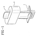
- the gas turbine blade 1 is placed in a mold 2, typically of rubber or plastic, which surrounds the blade with only the tip of the blade 3 to be coated being exposed, which mold is integral with the fixture base 4 as shown in Figure 2 .
- This blade mold assists in preventing plating or cleaning of undesired areas and in securing the blade into the fixture base 4.
- abrasive particles are anchored to the bond coat by tack plating. This is carried out by electroplating from a bath of plating solution having abrasive particles contained therein.
- the particles are placed in direct and stable contact with the blade tip, and then electroplating around them a thin layer of Ni or Co.
- the abrasive particles are typically hard ceramic particles and can be, for example, CBN or SiC, with or without a metal coating.
- the preferred particle size of the abrasive particles for use in gas turbine blade tips is generally from about 4 to 7 mils.
- 80-100 U. S. mesh uncoated CBN particles can be anchored with a 0.0004 inch thick nickel layer deposited from a nickel sulfamate plating solution having a nickel content of about 80 g/l.
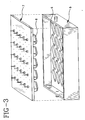
- the abrasive tack plating is carried out by placing an abrasive tack fixture 5, shown in Figure 3 , on top of the fixture base 4 of Figure 2 .
- the tapered recesses 6 in the abrasive tack fixture 5 fit around the turbine blade tips 3 and serve to direct the abrasive particles into pockets which extend to the blade tips 3 and maintain the abrasive particles in contact with the blade tips during the tack plating.
- the anode array lid 7 is attached to the abrasive tack fixture 5 and positioned above the blade tips 3 so that there is an anode 8 positioned in each tapered recess 6 above each blade tip 3 during the abrasive tack plating.
- the assembled tack fixture is filled with plating solution and the abrasive particles are introduced into the recesses.
- the plating current is then turned on and the fixture is vibrated at a high frequency and low amplitude for several seconds to uniformly distribute the abrasive particles on the tip surface.
- a layer of plating of about 0.0003 to 0.0005 inches is generally desired to tack the abrasive particles to the bond coat.
- the abrasive particles are embedded in a metal matrix by entrapment plating an infill of metal alloy powder from a bath of nickel or cobalt plating solution having the metal powder contained therein.
- Preferred metal alloy powders are a CrAlX 2 or M 2 CrAlX 2 powder, wherein M 2 is one ofNi and Co and X 2 is one of Hf and Y.
- a fine CrAlX 2 or M 2 CrAlX 2 powder have a size of 10 microns or less with a concentration of 500 to 2000g/l in the plating solution is preferred.
- CoCrAlHf powder (99 % less than 10 microns) is entrapment plated in a nickel sulfamate solution.
- a surfactant is preferably used to disperse the powder in the plating solution, allowing for high concentrations of the powder in the plating solution without agglomeration or precipitation.
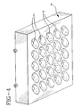
- Entrapment plating of the metal alloy powder is preferably carried out in an array of independent plating cells with a blade fixtured in each cell by placing the entrapment plating fixture 9 of Figure 4 on top of the fixture base 4 of Figure 2 .
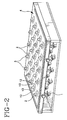
- the array can comprise any number of cells with from 20 to 40 cells per array being typical for aircraft turbine blades. An array of 25 blades is shown in Figure 2 .
- Each of the blade tips 3 in the fixture base 4 fits into a corresponding plating cell 10 of the entrapment plating fixture 9 shown in Figure 4 .
- Individual anodes 11 are affixed to plastic spacers near the top of each cell 10 and upon filling of the cells become fully submerged in the plating solution. Vent holes in the top of each cell permit the escape of entrapped air during filling.
- each blade tip 3 becomes enclosed in its own independent cell.
- the powder-laden plating solution is recirculated in a closed circuit through the inlet ports 12 and outlets ports 13 located in the fixture base 4 at the bottom of each enclosed independent plating cell.
- the fixture is vibrated at 30-35 Hz by means of an electromechanical vibrator. The vibration frequency controls the length of time that the powder particles remain in contact with the blade tip surface and controls the fraction of entrapped powder in the coating as well as assists in providing a uniform distribution of entrapped powder particles.
- the plating current density and waveform is important to providing suitable plating.
- the waveform contains short duration high amplitude reverse current pulses which help to remove loosely adherent particles, prevent nickel or cobalt depletion in the boundary layer, improve coating uniformity, and increase the throwing power of the solution.
- the reverse current pulse is generally repeated at least once every second, preferably a series of reverse current pulses is repeated once every 0.1 seconds.
- the coated blades are heat treated to diffuse the CrAlX 2 or M 2 CrAlX 2 powder composition into the plating metal matrix creating a dense homogeneous matrix for the abrasive particles.
- a typical heat treatment is at about 1975° F for 4 hours.
- Additional treatments of the abrasive coated tip could include coating, such as a diffusion aluminide coating, to further improve the oxidation resistance of the abrasive coated tip.
- FIG. 5 A schematic of the abrasive coated surface produced by this invention before a final heat treatment is shown in Figure 5 .
- the substrate surface 14 has a LPPS layer of bond coat 15 thereon with a layer of nickel 16 and abrasive particles 17 adhering thereto and an infill 18 surrounding the abrasive particles.
- the CrAlX 2 or M 2 CrAlX 2 powder and nickel plating become a homogenous phase 19 surrounding the abrasive particles 17.
- a major advantage of the process of this invention in the use of a LPPS bond coat is the mechanical strength and integrity it provides.
- the LPPS bond coat serves as a transitional zone between the plated matrix and the turbine blade substrate.
- the bond coat acts as a compliant interlayer, absorbing the stresses and dimensional changes associated with the electroplated deposit and more importantly the changes associated with engine operation.
- This bond coat also has a micro-rough surface resulting in a larger interface between the bond coat and the electroplated matrix.
- the increased surface area and resultant enhanced interdiffusion result in a greater bond strength of the abrasive tip.
- the bond coat provides closer compatibility with the composition of the entrapment matrix. This coating also provides improved oxidation and hot corrosion resistance.
- the bond coating provides environmental protection to the tip, as it remains intact as the abrasive portion of the tip wears and degrades. This process and coating also provide compositional flexibility.
- the composition of the bond coat can be readily adjusted to optimize for long term substrate compatibility, creep strength, oxidation and/or hot corrosion resistance.
- the bond coat can be doped with elements that enhance, by interdiffusion, the environmental resistance of the entrapment matrix, eg. Hf, Y, Pt, Al.
- the blade tips of a gas turbine blade are machined to prepare for the LPPS deposition.
- a 0.0025 inch thick NiCoCrAlY layer is deposited by low pressure plasma spray. Following the LPPS application, the deposit is peened and diffused at 1975° F for two hours.
- the LPPS coated tips are then glass-honed and the blades are masked and placed into the mold in the plating fixture base.
- the fixture is assembled and the blade tips undergo a pre-plate cleaning process (alkaline and acid clean).
- the cleaned surfaces are activated by means of a two-minute nickel sulfamate strike at 90 °F, 50 ASF.
- the abrasive tack fixture is assembled onto the plating fixture base and filled with nickel sulfamate plating solution 80/100 mesh CBN particles are introduced into each of the tapered recesses above the blades and the anode array lid is attached to the abrasive tack fixture.
- the assembled fixture is vibrated for a short time at a high frequency (100 Hz/10 seconds) at a low amplitude in order to distribute the CBN uniformly on top of the blade tips.
- CBN tack plating is carried out for 15 minutes at 30 ASF, resulting in a 0.0004 inch thick nickel tack layer.
- the assembled fixture is inverted and the plating solution is drained through a filter to recover the excess CBN material. Loosely adhered CBN particles are removed using a spray water rinse.
- the abrasive tack fixture is disassembled and the entrapment plating fixture is assembled onto the fixture base in order that a plating cell is positioned on top of each blade tip.
- the assembled fixture is placed on a vibrating mount and vibration is commenced at 33 Hz.
- the pulsing rectifier is turned on and the plating bath made of a nickel sulfamate plating solution with additions of 0.67v% of a surfactant and 500g/l of ultra fine CrAlHf or CoCrAlHf powder (100%-15 micron, 99%-10 micron) is introduced by means of pumps into the plating cells from a storage/overflow tank.
- the solution enters the plating cells via the bottom inlet ports.
- the entrapment plating bath is recirculated for several minutes through the vent holes and the storage tank while the bottom outlet ports remain closed or only partially open. Subsequently, the cell bottom outlet ports are opened and the air bleed holes are closed and the solution is recirculated in a closed circuit for the remainder of the process at a rate required to maintain a minimum velocity of 30 cm/s throughout the system.
- the total volume of recirculated plating solution depends on the number and size of the blades to be plated and is typically between 1 and 2 gallons for 20 to 40 blades.
- the temperature of the solution is maintained at 120 F.
- Entrapment plating is conducted for 210 minutes under current control at 30 ASF equivalent DC current density using the following pulsing cycle: 80 ms forward current at 47 ASF followed by 5 cycles of 1 ms/140 ASF reverse pulse and 3 ms without current.
- the powder fraction entrapped by this process is 40% by volume of the entrapment plated coating.
- the blades are removed from the fixture and unmasked, and placed in a vacuum furnace for a four hour diffusion process at 1975 F.
- the CrAlHf or CoCrAlHf powder particles are entirely dissolved in the nickel matrix producing a metal matrix composite of CBN particles embedded in a 100% dense NiCrAlHf or NiCoCrAlHf alloy.
- abrasive coated blade tips prepared by the process of this invention as demonstrated in Example I were subjected to a tensile strength test against blade tips with an abrasive coating prepared in accordance with U. S. Patent 5076897 wherein a bond coat of MCrAlY is applied by electrodeposition, followed by electrodeposition of abrasive particles with an MCrAlY infill around the abrasive particles and diffusion heat treatment.
- Tips prepared by the process of Example I and by the process of U. S. Patent 5076897 were epoxied or brazed (Au-Ni) to 1 inch diameter steel pull bars.
- the test conditions were room temperature and a constant strain rate of 0.05 inches/min.
- the tip prepared by the process of U. S. Patent 5076897 had a strength of 4.7 ksi.
- the failure locus was cohesive within the entrapment plated matrix and adhesive by dilamination of the interface between the base alloy of the blade tip and the plated matrix.
- the tip prepared by Example I had a strength of 27 ksi.
- the failure locus was adhesive by delamination of the LPPS/entrapment plated matrix interface.
Landscapes
- Chemical & Material Sciences (AREA)
- Engineering & Computer Science (AREA)
- Chemical Kinetics & Catalysis (AREA)
- Materials Engineering (AREA)
- Metallurgy (AREA)
- Organic Chemistry (AREA)
- Electrochemistry (AREA)
- Mechanical Engineering (AREA)
- General Engineering & Computer Science (AREA)
- Composite Materials (AREA)
- Inorganic Chemistry (AREA)
- Electroplating Methods And Accessories (AREA)
- Other Surface Treatments For Metallic Materials (AREA)
- Turbine Rotor Nozzle Sealing (AREA)
- Coating By Spraying Or Casting (AREA)
- Polishing Bodies And Polishing Tools (AREA)
Description
- During the operation of a gas turbine engine, it is desired to maintain minimum clearance between the tips of the turbine blades and the corresponding seals. A large gap results in decreased efficiency of the turbine, due to the escape of high-energy gases. Conversely, friction between the blades and seals causes excessive component wear and wastes energy. Since aircraft turbines experience cyclic mechanical and thermal load variations during operation their geometry varies during the different stages of the operating cycle. It is therefore impossible to set the necessary minimum clearance at the time of assembly. Active clearance control and abrasive blade tips are currently used to establish and maintain optimum clearance during operation. Abrasive blade tips are used to enable the blades to cut their own path in the seals during the first few operating cycles of the engine. Ideally, those tips should retain their cutting action over many operating cycles compensating for any progressive changes in turbine geometry. The tips are usually comprised of an abrasive particulate phase such as CBN, coated SiC, or another hard ceramic phase embedded in a suitable oxidation-resistant alloy matrix, such as MCrAlY, the M standing for either Ni or Co or both.
- Various methods have been described in the art for applying an abrasive coating on an article.
U. S. Patent 4249913 describes an alumina coated silicon carbide particle dispersed in an alloy attached to the end of a turbine blade by diffusion bonding, liquid phase bonding or brazing.U. S. Patent 4610698 describes a combination of sintering, plasma arc spraying, hot isostatic pressing and chemical milling to form an abrasive surface.U. S. Patent 4227703 describes a process of bonding a discrete shaped alloy to the tip, then entrapping thereon abrasive particles with a matrix containing Cr, Co and Ni applied by electrodeposition. -
U. S. Patent 4061430 teaches a socket structure for a ball point refill, which comprises a ball made of corundum and arranged inside an outer supporting shell provided in its interior with a compound bearing consisting of a backing shell having a hardness exceeding 800 kg/sq.mm Vickers and an inner lining facing the ball and having a hardness of less than 200 kg/sq.mm Vickers. - British Patent
2216899 - A more recent method is described in
U. S. Patent 5076897 , wherein a binding coat of MCrAlY is applied by electrodeposition, anchoring to the binding coat abrasive particles by composite electrodeposition and then plating an infill around the abrasive particles. This method is attractive due to its low cost and ease of manufacture; however, a problem with these abrasive tips is the low mechanical strength. This is due primarily to the weakness of the plated matrix and the interface between the plated matrix and the base alloy of the blade. - Furthermore, in
PCT patent WO 95/17535 - Furthermore, by the European Patent
718419 - Furthermore, by the European Patent
724657 - Furthermore, in
U. S. Patent 5665217 another method for forming abrasive surfaces on the tips of a plurality of workpieces such as the tips of gas turbine airfoil blades is disclosed, wherein it includes: (1) a mechanical masking device is provided having a plurality of openings arranged around the circumference of the device, (2) installing an array containing a plurality of workpieces to be coated within the mechanical masking device so that portions of the workpieces including the tips thereof extend through the openings, (3) immersing the mechanical masking device with the installed array of workpieces in a tank containing a plating bath with a matrix material and an abrasive grit material in slurry form so that the workpieces lie in a substantially horizontal plane, and (4) applying a current through the plating bath to form the abrasive surfaces on the tips of the workpieces. - Thus an object of this invention is to provide a cost effective means of applying durable abrasive coatings with a strong bond between the substrate and the abrasive coating.
-
-
Figure 1 shows a gas turbine blade secured in a mold. -
Figure 2 shows an array of blades in a fixture base. -
Figure 3 shows an abrasive tack fixture and an anode array. -
Figure 4 shows an entrapment plating fixture. -
Figure 5 shows schematically the structure of the abrasive coating adhering to the surface of the substrate prior to a final heat treatment. -
Figure 6 shows schematically the structure of the abrasive coating after a final heat treatment. - Briefly, the present invention provides a process for producing an abrasive coating on a substrate surface by applying a bond coat to the substrate surface by low pressure plasma spraying and anchoring to the bond coat abrasive particles by electroplating and embedding the particles into an oxidation resistant metal matrix by entrapment plating. More specifically, the coating is applied by: low pressure plasma spraying an M1CrAlX1 bond coat onto the substrate surface, wherein M1 is one or more of Ni and Co and X1 is one or more of Hf and Y; anchoring to the bond coat abrasive particles by electroplating from a bath of plating solution having abrasive particles contained therein; and entrapment electroplating an infill of CrAlX2or M2CrAlX2 powder around the abrasive particles from a bath of plating solution having CrAlX2 or M2CrAlX2 particles contained therein, wherein M2 is one or more of Ni and Co and X2 is one or more of Hf and Y. An improved electroplating process and an improved abrasive coated substrate are also disclosed.
- The method of the present invention introduces several major innovations: i) a low pressure plasma spray (LLPS)-deposited base layer which serves as a transition between the base alloy and the plated tip matrix and greatly improves the mechanical strength of the tip, and which also provides residual protection to the blade following complete wear of the abrasive; ii) a plating setup consisting of an array of independent plating cells resulting in efficient powder suspension and uniform conditions around each of the blades during plating; iii) high concentration of metallic powder in the plating bath suspended with the help of chemical surfactants; iv) the blades only partially submerged in a small volume of plating solution, thus avoiding problems associated with unwanted solution penetration into the inner passages of the blades; and v) high-frequency reverse-pulse plating resulting in a dense and uniform entrapment of a large volume fraction of powder at a significantly higher rate than in the prior art.
- This invention provides an improved method for the application of abrasive tips onto gas turbine blades by means of LPPS and entrapment plating. Typically, the blade tips produced by the method of the invention are comprised of a 0.002 inch to 0.003 inch thick oxidation-resistant MCrAlHf or MCrAlY LPPS base layer, and a 0.006 inch thick abrasive layer consisting of CBN abrasive particles embedded in a fully dense NiCrAlHf or NiCoCrAlHf oxidation-resistant metal matrix. The tips possess mechanical strength comparable to that of the previously known sprayed abrasive tips (see
U. S. Patent 4610698 ), but are easier and less costly to manufacture and are significantly stronger than entrapment-plated tips produced by methods of the prior art (seeU. S. Patent 5076897 ). - A bond coat is first applied to the substrate surface, eg. a gas turbine blade tip, by LPPS. This creates a dense, uniform layer essentially free of oxides or contaminants. Adhesion to the substrate is enhanced by a diffusion heat treatment after application. A suitable bond coat which provides strong adhesion between both the substrate surface and bond coat, as well as between the bond coat and the plated abrasive portion of the tip, while also providing protection to the substrate surface against wear, oxidation or erosion is a M1CrAlX1 bond coat, wherein M1 is one or more of Ni and Co and X1 is one or more of Hf and Y. A typical bond coat would be a NiCoCrAlY layer having a composition by weight percent of 32 % Ni, 21% Cr, 8 % Al, 0.5% Y, balance Co.
- To apply the bond coat by LPPS the substrate surface is first prepared for the LPPS deposition by, for example, machining and cleaning the blade tip surface. Typically the surface is cleaned by grit blasting with alumina particles. Then, for example, a-325 U. S. Sieve Series Mesh powder is applied by argonhelium plasma arc spraying in a low pressure chamber. The spray chamber is maintained at a pressure of about 40 Torr during spraying. The work piece blade is positioned with respect to the plasma arc device so that the tip cross section to be sprayed is normal to the axis along which the molten particles travel The blade is suitably masked around its periphery so that errant spray does not deposit on the sides of the blade. The blade tips are preheated, for example to a temperature of approximately 1300 F, and the bond coat is applied at a thickness effective to act as a bond coat and provide protection to the substrate. A typical thickness for an M1CrAlX1 bond coat is up to about 0.010 inches, preferably about 0.002 to 0.0003 inches thick.
- Following the LPPS, the deposited bond coat is peened and heat treated to effect interdiffusion between the bond coat and substrate and to remove any voids in the coating, remove loose particles, reduce surface roughness and to relieve any residual stress in the deposit. Typically a NiCoCrAlY would be heated at about 1975° F for about 2-4 hours under vacuum or a non-oxidizing atmosphere.
- The bond coat is then prepared for plating. Surface oxides are removed by, for example, alumina grit blasting then cleaned, for example, by use of an alkaline cleaner to remove organic residues and an acid bath to etch the surface. This is followed by a strike bath containing Ni or Co to provide a highly active surface layer of metal for plating. For example, the cleaned surface is activated by means of a two-minute nickel sulfamate strike providing a 0.0001 inch thick layer of nickel. For the cleaning and subsequent plating operations the blades are masked. Preferably, as shown in
Figure 1 , the gas turbine blade 1 is placed in amold 2, typically of rubber or plastic, which surrounds the blade with only the tip of theblade 3 to be coated being exposed, which mold is integral with the fixture base 4 as shown inFigure 2 . This blade mold assists in preventing plating or cleaning of undesired areas and in securing the blade into the fixture base 4. - Following preparation of the bond coat surface, abrasive particles are anchored to the bond coat by tack plating. This is carried out by electroplating from a bath of plating solution having abrasive particles contained therein.
- Preferably, the particles are placed in direct and stable contact with the blade tip, and then electroplating around them a thin layer of Ni or Co. The abrasive particles are typically hard ceramic particles and can be, for example, CBN or SiC, with or without a metal coating. The preferred particle size of the abrasive particles for use in gas turbine blade tips is generally from about 4 to 7 mils. For example, 80-100 U. S. mesh uncoated CBN particles can be anchored with a 0.0004 inch thick nickel layer deposited from a nickel sulfamate plating solution having a nickel content of about 80 g/l.
- The abrasive tack plating is carried out by placing an
abrasive tack fixture 5, shown inFigure 3 , on top of the fixture base 4 ofFigure 2 . The tapered recesses 6 in theabrasive tack fixture 5 fit around theturbine blade tips 3 and serve to direct the abrasive particles into pockets which extend to theblade tips 3 and maintain the abrasive particles in contact with the blade tips during the tack plating. Theanode array lid 7 is attached to theabrasive tack fixture 5 and positioned above theblade tips 3 so that there is ananode 8 positioned in eachtapered recess 6 above eachblade tip 3 during the abrasive tack plating. To anchor the abrasive particles to the tip the assembled tack fixture is filled with plating solution and the abrasive particles are introduced into the recesses. The plating current is then turned on and the fixture is vibrated at a high frequency and low amplitude for several seconds to uniformly distribute the abrasive particles on the tip surface. A layer of plating of about 0.0003 to 0.0005 inches is generally desired to tack the abrasive particles to the bond coat. - Following the tack operation, the abrasive particles are embedded in a metal matrix by entrapment plating an infill of metal alloy powder from a bath of nickel or cobalt plating solution having the metal powder contained therein. Preferred metal alloy powders are a CrAlX2 or M2CrAlX2 powder, wherein M2 is one ofNi and Co and X2 is one of Hf and Y. A fine CrAlX2 or M2CrAlX2 powder have a size of 10 microns or less with a concentration of 500 to 2000g/l in the plating solution is preferred. For example, CoCrAlHf powder (99 % less than 10 microns) is entrapment plated in a nickel sulfamate solution. A surfactant is preferably used to disperse the powder in the plating solution, allowing for high concentrations of the powder in the plating solution without agglomeration or precipitation.
- Entrapment plating of the metal alloy powder is preferably carried out in an array of independent plating cells with a blade fixtured in each cell by placing the
entrapment plating fixture 9 ofFigure 4 on top of the fixture base 4 ofFigure 2 . The array can comprise any number of cells with from 20 to 40 cells per array being typical for aircraft turbine blades. An array of 25 blades is shown inFigure 2 . Each of theblade tips 3 in the fixture base 4 fits into acorresponding plating cell 10 of theentrapment plating fixture 9 shown inFigure 4 .Individual anodes 11 are affixed to plastic spacers near the top of eachcell 10 and upon filling of the cells become fully submerged in the plating solution. Vent holes in the top of each cell permit the escape of entrapped air during filling. Following assembly of the fixture base 4 andplating fixture 9 eachblade tip 3 becomes enclosed in its own independent cell. During plating, the powder-laden plating solution is recirculated in a closed circuit through theinlet ports 12 andoutlets ports 13 located in the fixture base 4 at the bottom of each enclosed independent plating cell. The fixture is vibrated at 30-35 Hz by means of an electromechanical vibrator. The vibration frequency controls the length of time that the powder particles remain in contact with the blade tip surface and controls the fraction of entrapped powder in the coating as well as assists in providing a uniform distribution of entrapped powder particles. In addition the plating current density and waveform is important to providing suitable plating. Preferably the waveform contains short duration high amplitude reverse current pulses which help to remove loosely adherent particles, prevent nickel or cobalt depletion in the boundary layer, improve coating uniformity, and increase the throwing power of the solution. The reverse current pulse is generally repeated at least once every second, preferably a series of reverse current pulses is repeated once every 0.1 seconds. - Following plating the coated blades are heat treated to diffuse the CrAlX2 or M2CrAlX2 powder composition into the plating metal matrix creating a dense homogeneous matrix for the abrasive particles. A typical heat treatment is at about 1975° F for 4 hours. Additional treatments of the abrasive coated tip could include coating, such as a diffusion aluminide coating, to further improve the oxidation resistance of the abrasive coated tip.
- A schematic of the abrasive coated surface produced by this invention before a final heat treatment is shown in
Figure 5 . Thesubstrate surface 14 has a LPPS layer ofbond coat 15 thereon with a layer ofnickel 16 andabrasive particles 17 adhering thereto and aninfill 18 surrounding the abrasive particles. After heat treatment as shown inFigure 6 the CrAlX2 or M2CrAlX2 powder and nickel plating become ahomogenous phase 19 surrounding theabrasive particles 17. - A major advantage of the process of this invention in the use of a LPPS bond coat is the mechanical strength and integrity it provides. The LPPS bond coat serves as a transitional zone between the plated matrix and the turbine blade substrate. The bond coat acts as a compliant interlayer, absorbing the stresses and dimensional changes associated with the electroplated deposit and more importantly the changes associated with engine operation. This bond coat also has a micro-rough surface resulting in a larger interface between the bond coat and the electroplated matrix. The increased surface area and resultant enhanced interdiffusion result in a greater bond strength of the abrasive tip. In addition the bond coat provides closer compatibility with the composition of the entrapment matrix. This coating also provides improved oxidation and hot corrosion resistance. The bond coating provides environmental protection to the tip, as it remains intact as the abrasive portion of the tip wears and degrades. This process and coating also provide compositional flexibility. The composition of the bond coat can be readily adjusted to optimize for long term substrate compatibility, creep strength, oxidation and/or hot corrosion resistance. The bond coat can be doped with elements that enhance, by interdiffusion, the environmental resistance of the entrapment matrix, eg. Hf, Y, Pt, Al.
- The blade tips of a gas turbine blade are machined to prepare for the LPPS deposition. A 0.0025 inch thick NiCoCrAlY layer is deposited by low pressure plasma spray. Following the LPPS application, the deposit is peened and diffused at 1975° F for two hours.
- The LPPS coated tips are then glass-honed and the blades are masked and placed into the mold in the plating fixture base. The fixture is assembled and the blade tips undergo a pre-plate cleaning process (alkaline and acid clean). The cleaned surfaces are activated by means of a two-minute nickel sulfamate strike at 90 °F, 50 ASF.
- Following the strike, the abrasive tack fixture is assembled onto the plating fixture base and filled with nickel sulfamate plating solution 80/100 mesh CBN particles are introduced into each of the tapered recesses above the blades and the anode array lid is attached to the abrasive tack fixture. The assembled fixture is vibrated for a short time at a high frequency (100 Hz/10 seconds) at a low amplitude in order to distribute the CBN uniformly on top of the blade tips. CBN tack plating is carried out for 15 minutes at 30 ASF, resulting in a 0.0004 inch thick nickel tack layer. The assembled fixture is inverted and the plating solution is drained through a filter to recover the excess CBN material. Loosely adhered CBN particles are removed using a spray water rinse.
- The abrasive tack fixture is disassembled and the entrapment plating fixture is assembled onto the fixture base in order that a plating cell is positioned on top of each blade tip. The assembled fixture is placed on a vibrating mount and vibration is commenced at 33 Hz. The pulsing rectifier is turned on and the plating bath made of a nickel sulfamate plating solution with additions of 0.67v% of a surfactant and 500g/l of ultra fine CrAlHf or CoCrAlHf powder (100%-15 micron, 99%-10 micron) is introduced by means of pumps into the plating cells from a storage/overflow tank. The solution enters the plating cells via the bottom inlet ports. To completely remove any entrapped air the entrapment plating bath is recirculated for several minutes through the vent holes and the storage tank while the bottom outlet ports remain closed or only partially open. Subsequently, the cell bottom outlet ports are opened and the air bleed holes are closed and the solution is recirculated in a closed circuit for the remainder of the process at a rate required to maintain a minimum velocity of 30 cm/s throughout the system. The total volume of recirculated plating solution depends on the number and size of the blades to be plated and is typically between 1 and 2 gallons for 20 to 40 blades. The temperature of the solution is maintained at 120 F. Entrapment plating is conducted for 210 minutes under current control at 30 ASF equivalent DC current density using the following pulsing cycle: 80 ms forward current at 47 ASF followed by 5 cycles of 1 ms/140 ASF reverse pulse and 3 ms without current. The powder fraction entrapped by this process is 40% by volume of the entrapment plated coating.
- The blades are removed from the fixture and unmasked, and placed in a vacuum furnace for a four hour diffusion process at 1975 F. At the end of the process, the CrAlHf or CoCrAlHf powder particles are entirely dissolved in the nickel matrix producing a metal matrix composite of CBN particles embedded in a 100% dense NiCrAlHf or NiCoCrAlHf alloy.
- The abrasive coated blade tips prepared by the process of this invention as demonstrated in Example I were subjected to a tensile strength test against blade tips with an abrasive coating prepared in accordance with
U. S. Patent 5076897 wherein a bond coat of MCrAlY is applied by electrodeposition, followed by electrodeposition of abrasive particles with an MCrAlY infill around the abrasive particles and diffusion heat treatment. - The equipment utilized was an Instron 60 kpf tensile testing machine. Tips prepared by the process of Example I and by the process of
U. S. Patent 5076897 were epoxied or brazed (Au-Ni) to 1 inch diameter steel pull bars. The test conditions were room temperature and a constant strain rate of 0.05 inches/min. - The result was that the tip prepared by the process of
U. S. Patent 5076897 had a strength of 4.7 ksi. The failure locus was cohesive within the entrapment plated matrix and adhesive by dilamination of the interface between the base alloy of the blade tip and the plated matrix. The tip prepared by Example I had a strength of 27 ksi. The failure locus was adhesive by delamination of the LPPS/entrapment plated matrix interface.
Claims (19)
- A process for producing an abrasive coating on a substrate surface comprising:applying a bond coat to the substrate surface by low pressure plasma spraying;anchoring to the bond coat abrasive particles by entrapment plating in a metal matrix.
- Process of Claim 1 wherein an M1CrAlX1 bond coat is applied by low pressure plasma spraying, wherein M1 is one or more of Ni and Co and X1 is one or more of Y and Hf;
the abrasive particles are anchored to the bond coat by tack plating; and
an infill of CrAlX2 or MiCrAlX2 powder is electroplated around the abrasive particles from a bath of plating solution having the CrAlX2 or M2CrAlX2 particles contained therein, wherein M2 is one or more of Ni and Co and X2 is one or more of Y and Hf. - Process of Claim 2 wherein the electroplating is carried out with plating solution containing one or more of Ni and Co.
- Process of Claim 3 further comprising heat treating the infill electroplated substrate to diffuse the CrAlX2 or M2CrAlX2 powder with the Ni or Co plating.
- Process of Claim 3 wherein the bond coat surface is cleaned and the surface activated for electroplating with a strike containing one or more of Ni or Co.
- Process of Claim 2 wherein the substrate is a nickel or cobalt based superalloy.
- Process of Claim 6 wherein the substrate surface is the tip of a gas turbine blade.
- Process of Claim 7 wherein the electroplating is carried out in an array of independent plating cells with one blade fixtured in each of the cells.
- Process of Claim 8 wherein the CrAlX2 or M2CrAlX2 powder is dispersed in a bath of plating solution containing a surfactant.
- Process of Claim 9 wherein only the blade tip of the gas turbine blade is submerged in the plating solution during electroplating.
- Process of Claim 10 wherein electroplating is carried out with a reverse pulse current
- Process of Claim 7 wherein the abrasive particle is a CBN particle.
- Process of Claim 10 wherein the blade is placed in a mold leaving the blade tip exposed for plating.
- Process of Claim 9 wherein the CrAlX2 or M2CrAlX2 powder is of a size of 10 microns or less and the concentration of powder in the plating solution is from about 500 to 2000 g/l.
- An abrasive coated substrate comprising:a Ni or Co based superalloy substrate;a low pressure plasma sprayed bond coat; andan entrapment plated abrasive particles in a metal matrix.
- Substrate of Claim 15 wherein the bond coat is an M1CrAlX1 wherein M1 is one or more of Ni and Co and X1 is one or more of Y and Hf.
- Substrate of Claim 16 wherein the metal matrix is an M2CrAlX2 wherein M2 is one or more of Ni and Co and X2 is one or more of Y and Hf.
- Substrate of Claim 17 wherein the abrasive particle is CBN.
- Substrate of Claim 17 wherein the abrasive coated substrate is heat treated to diffuse the metal matrix.
Applications Claiming Priority (3)
| Application Number | Priority Date | Filing Date | Title |
|---|---|---|---|
| US08/965,559 US5935407A (en) | 1997-11-06 | 1997-11-06 | Method for producing abrasive tips for gas turbine blades |
| US965559 | 1997-11-06 | ||
| PCT/US1998/019904 WO1999024647A1 (en) | 1997-11-06 | 1998-09-23 | Method for producing abrasive tips for gas turbine blades |
Publications (3)
| Publication Number | Publication Date |
|---|---|
| EP1042541A1 EP1042541A1 (en) | 2000-10-11 |
| EP1042541A4 EP1042541A4 (en) | 2006-07-05 |
| EP1042541B1 true EP1042541B1 (en) | 2014-12-31 |
Family
ID=25510145
Family Applications (1)
| Application Number | Title | Priority Date | Filing Date |
|---|---|---|---|
| EP98953184.3A Expired - Lifetime EP1042541B1 (en) | 1997-11-06 | 1998-09-23 | Method for producing abrasive tips for gas turbine blades |
Country Status (10)
| Country | Link |
|---|---|
| US (2) | US5935407A (en) |
| EP (1) | EP1042541B1 (en) |
| JP (1) | JP4658317B2 (en) |
| KR (1) | KR100586436B1 (en) |
| CN (1) | CN100439567C (en) |
| AU (1) | AU741526B2 (en) |
| CA (1) | CA2306781C (en) |
| IL (1) | IL135716A (en) |
| NO (1) | NO321452B1 (en) |
| WO (1) | WO1999024647A1 (en) |
Cited By (2)
| Publication number | Priority date | Publication date | Assignee | Title |
|---|---|---|---|---|
| EP3121307A1 (en) | 2015-07-20 | 2017-01-25 | MTU Aero Engines GmbH | Wear resistance layer and process for its manufacturing |
| US11686208B2 (en) | 2020-02-06 | 2023-06-27 | Rolls-Royce Corporation | Abrasive coating for high-temperature mechanical systems |
Families Citing this family (93)
| Publication number | Priority date | Publication date | Assignee | Title |
|---|---|---|---|---|
| US5935407A (en) * | 1997-11-06 | 1999-08-10 | Chromalloy Gas Turbine Corporation | Method for producing abrasive tips for gas turbine blades |
| US6387527B1 (en) * | 1999-10-04 | 2002-05-14 | General Electric Company | Method of applying a bond coating and a thermal barrier coating on a metal substrate, and related articles |
| US6468040B1 (en) | 2000-07-24 | 2002-10-22 | General Electric Company | Environmentally resistant squealer tips and method for making |
| JP2002256808A (en) * | 2001-02-28 | 2002-09-11 | Mitsubishi Heavy Ind Ltd | Combustion engine, gas turbine and grinding layer |
| JP3801452B2 (en) | 2001-02-28 | 2006-07-26 | 三菱重工業株式会社 | Abrasion resistant coating and its construction method |
| JP2004523767A (en) * | 2001-03-16 | 2004-08-05 | シーメンス アクチエンゲゼルシヤフト | Non-destructive inspection method for carbide-containing alloy or alloy whose surface vicinity is sulfided and method for manufacturing gas turbine blade |
| US6537021B2 (en) * | 2001-06-06 | 2003-03-25 | Chromalloy Gas Turbine Corporation | Abradeable seal system |
| JP2002371803A (en) * | 2001-06-13 | 2002-12-26 | Mitsubishi Heavy Ind Ltd | Forming method for wear resistance layer for moving blade, wear resistance layer and regenerating method thereof |
| US6780458B2 (en) * | 2001-08-01 | 2004-08-24 | Siemens Westinghouse Power Corporation | Wear and erosion resistant alloys applied by cold spray technique |
| JP2003148103A (en) * | 2001-11-09 | 2003-05-21 | Mitsubishi Heavy Ind Ltd | Turbine and its manufacturing method |
| US6706319B2 (en) | 2001-12-05 | 2004-03-16 | Siemens Westinghouse Power Corporation | Mixed powder deposition of components for wear, erosion and abrasion resistant applications |
| US6833203B2 (en) * | 2002-08-05 | 2004-12-21 | United Technologies Corporation | Thermal barrier coating utilizing a dispersion strengthened metallic bond coat |
| US9284647B2 (en) * | 2002-09-24 | 2016-03-15 | Mitsubishi Denki Kabushiki Kaisha | Method for coating sliding surface of high-temperature member, high-temperature member and electrode for electro-discharge surface treatment |
| KR101063575B1 (en) * | 2002-09-24 | 2011-09-07 | 미츠비시덴키 가부시키가이샤 | Sliding surface coating method of high temperature member and electrode for high temperature member and discharge surface treatment |
| CN1692179B (en) * | 2002-10-09 | 2011-07-13 | 石川岛播磨重工业株式会社 | Rotor and coating method therefor |
| DE10251902B4 (en) * | 2002-11-07 | 2009-05-07 | Fraunhofer-Gesellschaft zur Förderung der angewandten Forschung e.V. | Process for coating a substrate and coated article |
| EP1428982B1 (en) * | 2002-12-06 | 2009-02-04 | ALSTOM Technology Ltd | A method of depositing a local MCrAIY-coating |
| US20050003172A1 (en) * | 2002-12-17 | 2005-01-06 | General Electric Company | 7FAstage 1 abradable coatings and method for making same |
| DE10259362A1 (en) * | 2002-12-18 | 2004-07-08 | Siemens Ag | Process for depositing an alloy on a substrate |
| DE60307041T2 (en) | 2003-03-21 | 2007-01-11 | Alstom Technology Ltd. | Method for applying a dense wear protection layer and sealing system |
| CH696854A5 (en) | 2003-04-14 | 2007-12-31 | Alstom Technology Ltd | Thermal turbomachinery. |
| US6921251B2 (en) * | 2003-09-05 | 2005-07-26 | General Electric Company | Aluminide or chromide coating of turbine engine rotor component |
| US20060051502A1 (en) * | 2004-09-08 | 2006-03-09 | Yiping Hu | Methods for applying abrasive and environment-resistant coatings onto turbine components |
| US20060057418A1 (en) | 2004-09-16 | 2006-03-16 | Aeromet Technologies, Inc. | Alluminide coatings containing silicon and yttrium for superalloys and method of forming such coatings |
| PL1802784T3 (en) * | 2004-09-16 | 2012-07-31 | Mt Coatings Llc | Gas turbine engine components with aluminide coatings and method of forming such aluminide coatings on gas turbine engine components |
| US9133718B2 (en) | 2004-12-13 | 2015-09-15 | Mt Coatings, Llc | Turbine engine components with non-aluminide silicon-containing and chromium-containing protective coatings and methods of forming such non-aluminide protective coatings |
| US7384522B2 (en) * | 2005-04-29 | 2008-06-10 | United Technologies Corporation | Ergonomic loading apparatus for electroplating processes |
| US20060266446A1 (en) * | 2005-05-25 | 2006-11-30 | Osenbach John W | Whisker-free electronic structures |
| EP1743957A1 (en) * | 2005-07-14 | 2007-01-17 | Sulzer Metco (US) Inc. | Process for treating the tip of a turbine blade and turbine blade treated by such a process |
| DE102005052676A1 (en) * | 2005-11-04 | 2007-05-16 | Bosch Gmbh Robert | Device for surface treatment of workpieces |
| US8137820B2 (en) | 2006-02-24 | 2012-03-20 | Mt Coatings, Llc | Roughened coatings for gas turbine engine components |
| DE102006016995A1 (en) * | 2006-04-11 | 2007-10-18 | Mtu Aero Engines Gmbh | Component with an armor |
| US7989020B2 (en) * | 2007-02-08 | 2011-08-02 | Honeywell International Inc. | Method of forming bond coating for a thermal barrier coating |
| JP4910096B2 (en) * | 2007-05-04 | 2012-04-04 | エムティーユー エアロ エンジンズ ゲーエムベーハー | Method for applying abrasive coatings to gas turbine components |
| US20080286108A1 (en) * | 2007-05-17 | 2008-11-20 | Honeywell International, Inc. | Cold spraying method for coating compressor and turbine blade tips with abrasive materials |
| DE102007056452A1 (en) | 2007-11-23 | 2009-05-28 | Mtu Aero Engines Gmbh | Sealing system of a turbomachine |
| US8431238B2 (en) * | 2008-02-19 | 2013-04-30 | Parker-Hannifin Corporation | Protective coating for metallic seals |
| DE102008026936A1 (en) * | 2008-06-05 | 2009-12-10 | Mtu Aero Engines Gmbh | Apparatus for use in a process for producing a protective layer and process for producing a protective layer |
| DE102008045256A1 (en) * | 2008-09-01 | 2010-03-04 | Rena Gmbh | Apparatus and method for the wet treatment of different substrates |
| DE102008053394A1 (en) * | 2008-10-27 | 2010-04-29 | Mtu Aero Engines Gmbh | Device for partially covering a component zone |
| DE102009018685A1 (en) | 2009-04-23 | 2010-10-28 | Mtu Aero Engines Gmbh | Method for producing an armor of a blade tip as well as correspondingly produced blades and gas turbines |
| US20110164961A1 (en) * | 2009-07-14 | 2011-07-07 | Thomas Alan Taylor | Coating system for clearance control in rotating machinery |
| RU2569254C2 (en) | 2009-08-14 | 2015-11-20 | Сэнт-Гобэн Эбрейзивс, Инк. | Abrasive article |
| WO2011020109A2 (en) * | 2009-08-14 | 2011-02-17 | Saint-Gobain Abrasives, Inc. | Abrasive articles including abrasive particles bonded to an elongated body, and methods of forming thereof |
| US8236163B2 (en) * | 2009-09-18 | 2012-08-07 | United Technologies Corporation | Anode media for use in electroplating processes, and methods of cleaning thereof |
| CA2719273C (en) * | 2009-11-02 | 2017-03-28 | Alstom Technology Ltd. | Wear-resistant and oxidation-resistant turbine blade |
| EP2317078B2 (en) * | 2009-11-02 | 2021-09-01 | Ansaldo Energia IP UK Limited | Abrasive single-crystal turbine blade |
| DE102009055914A1 (en) * | 2009-11-27 | 2011-06-09 | Rolls-Royce Deutschland Ltd & Co Kg | Sealing rings for a labyrinth seal |
| FR2959528B1 (en) * | 2010-04-29 | 2012-06-08 | Snecma | REMOVABLE MASK FOR A DRAFT PLATFORM OR A TURBOMACHINE DISPENSER SECTOR |
| TWI466990B (en) | 2010-12-30 | 2015-01-01 | 聖高拜磨料有限公司 | Abrasive article and forming method |
| CN103717344B (en) * | 2011-05-10 | 2016-01-20 | 苏舍涡轮服务芬洛有限公司 | Processes used to clad substrates |
| KR101618040B1 (en) | 2011-09-16 | 2016-05-04 | 생-고뱅 어브레이시브즈, 인코포레이티드 | Abrasive article and method of forming |
| JP5869680B2 (en) | 2011-09-29 | 2016-02-24 | サンーゴバン アブレイシブズ,インコーポレイティド | Abrasive article comprising abrasive particles bonded to an elongated substrate body having a barrier layer and method of forming the same |
| US8808870B2 (en) * | 2011-11-28 | 2014-08-19 | Kennametal Inc. | Functionally graded coating |
| TW201404528A (en) * | 2012-06-29 | 2014-02-01 | 聖高拜磨料有限公司 | Abrasive article and forming method |
| TW201402274A (en) * | 2012-06-29 | 2014-01-16 | 聖高拜磨料有限公司 | Abrasive article and forming method |
| TWI477343B (en) | 2012-06-29 | 2015-03-21 | Saint Gobain Abrasives Inc | Abrasive article and method of forming |
| TWI474889B (en) * | 2012-06-29 | 2015-03-01 | 聖高拜磨料有限公司 | Abrasive article and forming method |
| TW201404527A (en) | 2012-06-29 | 2014-02-01 | 聖高拜磨料有限公司 | Abrasive article and forming method |
| US9598973B2 (en) * | 2012-11-28 | 2017-03-21 | General Electric Company | Seal systems for use in turbomachines and methods of fabricating the same |
| TW201441355A (en) | 2013-04-19 | 2014-11-01 | 聖高拜磨料有限公司 | Abrasive article and method of forming same |
| DE102013218687A1 (en) * | 2013-09-18 | 2015-04-02 | MTU Aero Engines AG | Galvanized wear protection coating and method therefor |
| US9511436B2 (en) | 2013-11-08 | 2016-12-06 | General Electric Company | Composite composition for turbine blade tips, related articles, and methods |
| US9920444B2 (en) | 2014-05-22 | 2018-03-20 | The Boeing Company | Co-bonded electroformed abrasion strip |
| US9957629B2 (en) | 2014-08-27 | 2018-05-01 | Praxair S.T. Technology, Inc. | Electroplated coatings |
| US20160237832A1 (en) * | 2015-02-12 | 2016-08-18 | United Technologies Corporation | Abrasive blade tip with improved wear at high interaction rate |
| TWI664057B (en) | 2015-06-29 | 2019-07-01 | 美商聖高拜磨料有限公司 | Abrasive article and method of forming |
| RU2610188C1 (en) * | 2015-10-07 | 2017-02-08 | Федеральное государственное унитарное предприятие "Всероссийский научно-исследовательский институт авиационных материалов" (ФГУП "ВИАМ") | Method for protection of gas turbine components made from nickel alloys |
| US10527524B2 (en) * | 2016-10-26 | 2020-01-07 | United Technologies Corporation | Method of inspecting component surface with marking media |
| US11078588B2 (en) | 2017-01-09 | 2021-08-03 | Raytheon Technologies Corporation | Pulse plated abrasive grit |
| US10822967B2 (en) | 2017-02-01 | 2020-11-03 | Raytheon Technologies Corporation | Wear resistant coating, method of manufacture thereof and articles comprising the same |
| CA3052721A1 (en) * | 2017-02-07 | 2018-08-16 | Oerlikon Metco Ag, Wohlen | Abradable coating |
| DE102017208529A1 (en) * | 2017-05-19 | 2018-11-22 | Continental Teves Ag & Co. Ohg | Brake disc with a friction ring made of PMMC material |
| KR101985110B1 (en) * | 2017-11-28 | 2019-05-31 | 두산중공업 주식회사 | Steam turbine |
| US10544699B2 (en) | 2017-12-19 | 2020-01-28 | Rolls-Royce Corporation | System and method for minimizing the turbine blade to vane platform overlap gap |
| US10927685B2 (en) * | 2018-07-19 | 2021-02-23 | Raytheon Technologies Corporation | Coating to improve oxidation and corrosion resistance of abrasive tip system |
| US11073028B2 (en) | 2018-07-19 | 2021-07-27 | Raytheon Technologies Corporation | Turbine abrasive blade tips with improved resistance to oxidation |
| US11028721B2 (en) * | 2018-07-19 | 2021-06-08 | Ratheon Technologies Corporation | Coating to improve oxidation and corrosion resistance of abrasive tip system |
| CN109338288B (en) * | 2018-09-17 | 2020-09-18 | 中国科学院金属研究所 | A kind of gas turbine blade tip protective coating and preparation method and application thereof |
| US10954803B2 (en) | 2019-01-17 | 2021-03-23 | Rolls-Royce Corporation | Abrasive coating for high temperature mechanical systems |
| IT201900003691A1 (en) * | 2019-03-13 | 2020-09-13 | Nuovo Pignone Tecnologie Srl | Abrasive terminal of a rotor blade for a turboexpander |
| DE102019207350A1 (en) * | 2019-05-20 | 2020-11-26 | Siemens Aktiengesellschaft | Welding process with coated abrasive particles, coated abrasive particles, layer system and sealing system |
| US20230258094A1 (en) * | 2019-12-19 | 2023-08-17 | Raytheon Technologies Corporation | Barrier to prevent super alloy depletion into nickel-cbn blade tip coating |
| US11866830B2 (en) | 2020-03-13 | 2024-01-09 | Rtx Corporation | Abrasive tip coating |
| US11536151B2 (en) * | 2020-04-24 | 2022-12-27 | Raytheon Technologies Corporation | Process and material configuration for making hot corrosion resistant HPC abrasive blade tips |
| CA3206459A1 (en) * | 2020-12-15 | 2022-06-23 | Oerlikon Surface Solutions Ag, Pfaffikon | Coating for thermally and abrasively loaded turbine blades |
| CN114645306B (en) * | 2022-02-25 | 2024-04-09 | 中国航发北京航空材料研究院 | Method for preparing large-size cBN particles nickel-based coating on the surface of complex-shaped workpieces |
| EP4245963B1 (en) * | 2022-03-16 | 2025-09-10 | Rolls-Royce Deutschland Ltd & Co KG | Gas turbine engine and method for manufacturing a rotor blade |
| US11713681B1 (en) | 2022-05-18 | 2023-08-01 | Raytheon Technologies Corporation | Fan blade repair systems and methods |
| CN115637400B (en) * | 2022-11-18 | 2023-03-21 | 矿冶科技集团有限公司 | Titanium alloy blade with high-bonding-force wear-resistant protective coating and preparation method thereof |
| CN116121831A (en) * | 2022-12-13 | 2023-05-16 | 中国科学院金属研究所 | cBN ceramic particle/aluminide composite coating and preparation method thereof |
| EP4728126A2 (en) * | 2023-06-13 | 2026-04-22 | RTX Corporation | Nickel plating |
| FR3158748A1 (en) * | 2024-01-31 | 2025-08-01 | Safran | Method of depositing an abrasive coating on an aircraft turbine blade tip |
Family Cites Families (41)
| Publication number | Priority date | Publication date | Assignee | Title |
|---|---|---|---|---|
| US779639A (en) * | 1903-04-29 | 1905-01-10 | Edson G Case | Method of fastening abrasive material to metal bodies. |
| US3061525A (en) * | 1959-06-22 | 1962-10-30 | Platecraft Of America Inc | Method for electroforming and coating |
| NL267501A (en) * | 1960-07-26 | |||
| GB1218179A (en) * | 1967-04-18 | 1971-01-06 | Bristol Aerojet Ltd | Improvements relating to electrodeposited coatings |
| GB1329081A (en) * | 1970-08-27 | 1973-09-05 | Bristol Aerojet Ltd | Electrodeposition of composite coatings |
| US3830711A (en) * | 1972-01-19 | 1974-08-20 | Bristol Aerojet Ltd | Electrodeposition of composite coatings |
| US4061430A (en) * | 1972-06-02 | 1977-12-06 | Montblanc-Simplo Gmbh. | Socket structure for the ball of a ball point pen refill |
| GB1347184A (en) * | 1972-07-07 | 1974-02-27 | Bristol Aerojet Ltd | Electrodeposition of composite coatings |
| US4152223A (en) * | 1977-07-13 | 1979-05-01 | United Technologies Corporation | Plasma sprayed MCrAlY coating and coating method |
| US4305792A (en) * | 1977-12-21 | 1981-12-15 | Bristol Aerojet Limited | Processes for the electrodeposition of composite coatings |
| US4148494A (en) * | 1977-12-21 | 1979-04-10 | General Electric Company | Rotary labyrinth seal member |
| US4214355A (en) * | 1977-12-21 | 1980-07-29 | General Electric Company | Method for repairing a turbomachinery blade tip |
| US4169020A (en) * | 1977-12-21 | 1979-09-25 | General Electric Company | Method for making an improved gas seal |
| US4222828A (en) * | 1978-06-06 | 1980-09-16 | Akzo N.V. | Process for electro-codepositing inorganic particles and a metal on a surface |
| US4227703A (en) * | 1978-11-27 | 1980-10-14 | General Electric Company | Gas seal with tip of abrasive particles |
| US4232995A (en) * | 1978-11-27 | 1980-11-11 | General Electric Company | Gas seal for turbine blade tip |
| US4249913A (en) * | 1979-05-21 | 1981-02-10 | United Technologies Corporation | Alumina coated silicon carbide abrasive |
| US4744725A (en) * | 1984-06-25 | 1988-05-17 | United Technologies Corporation | Abrasive surfaced article for high temperature service |
| US4610698A (en) * | 1984-06-25 | 1986-09-09 | United Technologies Corporation | Abrasive surface coating process for superalloys |
| US4608128A (en) * | 1984-07-23 | 1986-08-26 | General Electric Company | Method for applying abrasive particles to a surface |
| US4608145A (en) * | 1984-07-23 | 1986-08-26 | General Electric Company | Electroplating tape |
| US4789441A (en) * | 1984-10-05 | 1988-12-06 | John Foster | Metallic protective coatings and method of making |
| GB2182055B (en) * | 1985-10-28 | 1989-10-18 | Baj Ltd | Improvements relating to electrodeposited coatings |
| FR2617510B1 (en) * | 1987-07-01 | 1991-06-07 | Snecma | METHOD FOR THE ELECTROLYTIC CODEPOSITION OF A NICKEL-COBALT MATRIX AND CERAMIC PARTICLES AND COATING OBTAINED |
| US4851188A (en) * | 1987-12-21 | 1989-07-25 | United Technologies Corporation | Method for making a turbine blade having a wear resistant layer sintered to the blade tip surface |
| GB8806596D0 (en) * | 1988-03-19 | 1988-04-20 | Ae Turbine Components | Coatings |
| GB8818069D0 (en) * | 1988-07-29 | 1988-09-28 | Baj Ltd | Improvements relating to electrodeposited coatings |
| US5074970A (en) * | 1989-07-03 | 1991-12-24 | Kostas Routsis | Method for applying an abrasive layer to titanium alloy compressor airfoils |
| GB2241506A (en) * | 1990-02-23 | 1991-09-04 | Baj Ltd | Method of producing a gas turbine blade having an abrasive tip by electrodepo- sition. |
| GB2256434A (en) * | 1991-06-04 | 1992-12-09 | Rolls Royce Plc | Abrasive medium |
| US5817204A (en) * | 1991-06-10 | 1998-10-06 | Ultimate Abrasive Systems, L.L.C. | Method for making patterned abrasive material |
| GB9216706D0 (en) * | 1992-08-06 | 1992-09-23 | Baj Ltd | Electrodeposited composite coatings |
| US5389228A (en) * | 1993-02-04 | 1995-02-14 | United Technologies Corporation | Brush plating compressor blade tips |
| GB9303853D0 (en) * | 1993-02-25 | 1993-04-21 | Baj Coatings Ltd | Rotor blades |
| US5389229A (en) * | 1993-06-18 | 1995-02-14 | Surface Technology, Inc. | Prestabilization of particulate matter prior to their dispersion |
| US5486281A (en) * | 1993-10-15 | 1996-01-23 | United Technologies Corporation | Method for CBN tipping of HPC integrally bladed rotors |
| CN1034350C (en) * | 1993-12-07 | 1997-03-26 | 北京科技大学 | Gradient Ni, Co, Cr, Al, Si Hf, Yt/Al cladding and double-target sputtering technology |
| GB9326082D0 (en) * | 1993-12-21 | 1994-02-23 | Baj Coatings Ltd | Rotor blades |
| GB9414859D0 (en) * | 1994-07-22 | 1994-09-14 | Baj Coatings Ltd | Protective coating |
| GB9426257D0 (en) * | 1994-12-24 | 1995-03-01 | Rolls Royce Plc | Thermal barrier coating for a superalloy article and method of application |
| US5935407A (en) * | 1997-11-06 | 1999-08-10 | Chromalloy Gas Turbine Corporation | Method for producing abrasive tips for gas turbine blades |
-
1997
- 1997-11-06 US US08/965,559 patent/US5935407A/en not_active Expired - Lifetime
-
1998
- 1998-09-23 CN CNB98810895XA patent/CN100439567C/en not_active Expired - Lifetime
- 1998-09-23 CA CA2306781A patent/CA2306781C/en not_active Expired - Lifetime
- 1998-09-23 WO PCT/US1998/019904 patent/WO1999024647A1/en not_active Ceased
- 1998-09-23 JP JP2000519635A patent/JP4658317B2/en not_active Expired - Lifetime
- 1998-09-23 IL IL13571698A patent/IL135716A/en not_active IP Right Cessation
- 1998-09-23 AU AU10619/99A patent/AU741526B2/en not_active Expired
- 1998-09-23 EP EP98953184.3A patent/EP1042541B1/en not_active Expired - Lifetime
- 1998-09-23 KR KR1020007004944A patent/KR100586436B1/en not_active Expired - Lifetime
-
1999
- 1999-04-16 US US09/410,922 patent/US6194086B1/en not_active Expired - Lifetime
-
2000
- 2000-04-27 NO NO20002187A patent/NO321452B1/en not_active IP Right Cessation
Cited By (3)
| Publication number | Priority date | Publication date | Assignee | Title |
|---|---|---|---|---|
| EP3121307A1 (en) | 2015-07-20 | 2017-01-25 | MTU Aero Engines GmbH | Wear resistance layer and process for its manufacturing |
| DE102015213555A1 (en) | 2015-07-20 | 2017-03-09 | MTU Aero Engines AG | Sealing ridge armor and method of making the same |
| US11686208B2 (en) | 2020-02-06 | 2023-06-27 | Rolls-Royce Corporation | Abrasive coating for high-temperature mechanical systems |
Also Published As
| Publication number | Publication date |
|---|---|
| AU741526B2 (en) | 2001-12-06 |
| WO1999024647A1 (en) | 1999-05-20 |
| JP2001522944A (en) | 2001-11-20 |
| NO321452B1 (en) | 2006-05-15 |
| US5935407A (en) | 1999-08-10 |
| NO20002187D0 (en) | 2000-04-27 |
| CN100439567C (en) | 2008-12-03 |
| CA2306781A1 (en) | 1999-05-20 |
| US6194086B1 (en) | 2001-02-27 |
| CN1278873A (en) | 2001-01-03 |
| EP1042541A1 (en) | 2000-10-11 |
| NO20002187L (en) | 2000-07-04 |
| KR100586436B1 (en) | 2006-06-08 |
| JP4658317B2 (en) | 2011-03-23 |
| AU1061999A (en) | 1999-05-31 |
| EP1042541A4 (en) | 2006-07-05 |
| CA2306781C (en) | 2011-05-17 |
| IL135716A (en) | 2004-06-20 |
| KR20010024583A (en) | 2001-03-26 |
| IL135716A0 (en) | 2001-05-20 |
Similar Documents
| Publication | Publication Date | Title |
|---|---|---|
| EP1042541B1 (en) | Method for producing abrasive tips for gas turbine blades | |
| US5607561A (en) | Apparatus for abrasive tipping of integrally bladed rotors | |
| US5074970A (en) | Method for applying an abrasive layer to titanium alloy compressor airfoils | |
| CA2036904C (en) | Gas turbine blades | |
| EP0288156B1 (en) | Overlay coating | |
| RU2134313C1 (en) | Process of precipitation of coat on substrate ( versions ) | |
| US6706319B2 (en) | Mixed powder deposition of components for wear, erosion and abrasion resistant applications | |
| EP2584150A2 (en) | Components with laser cladding and methods of manufacture | |
| CN112708883B (en) | Preparation method of superhard boron carbide ceramic reinforced iron-based alloy composite wear-resistant coating | |
| UA46716C2 (en) | METHOD OF OBTAINING COVERAGE ON THE BASIS | |
| EP0612360B1 (en) | Electrodeposited composite coatings | |
| EP0686229B1 (en) | Method of producing an abrasive tip on a turbine blade | |
| CN115110024A (en) | MCrAlY coating containing active element modification Re-based diffusion barrier and preparation method thereof | |
| US7101448B2 (en) | Process for producing a cladding for a metallic component | |
| Manjunatha et al. | The effect of sealing on the wear behaviour of plasma sprayed Mo coating | |
| CN117107311A (en) | A Pt-modified blade tip protective coating and its preparation method | |
| CN116103617B (en) | MCrAlY coating containing ReCr-based diffusion barrier and preparation method thereof | |
| Adler et al. | Supersonic Rain and sand erosion research: Characterization and development of erosion resistant materials |
Legal Events
| Date | Code | Title | Description |
|---|---|---|---|
| PUAI | Public reference made under article 153(3) epc to a published international application that has entered the european phase |
Free format text: ORIGINAL CODE: 0009012 |
|
| 17P | Request for examination filed |
Effective date: 20000501 |
|
| AK | Designated contracting states |
Kind code of ref document: A1 Designated state(s): AT BE CH DE ES FR GB IE IT LI NL SE |
|
| RIN1 | Information on inventor provided before grant (corrected) |
Inventor name: HOWARD, PETER Inventor name: FUGGINI, JOSEPH, A. Inventor name: FENTON, RICHARD Inventor name: NENOV, KRASSIMIR, P. |
|
| RIC1 | Information provided on ipc code assigned before grant |
Ipc: C23C 14/16 20060101ALI20060320BHEP Ipc: C23C 14/34 20060101ALI20060320BHEP Ipc: C23C 4/08 20060101ALI20060320BHEP Ipc: C25D 5/34 20060101ALI20060320BHEP Ipc: C25D 5/50 20060101ALI20060320BHEP Ipc: C25D 7/00 20060101ALI20060320BHEP Ipc: C25D 5/18 20060101ALI20060320BHEP Ipc: C25D 5/02 20060101ALI20060320BHEP Ipc: C25D 15/00 20060101ALI20060320BHEP Ipc: C23C 28/00 20060101AFI20060320BHEP |
|
| A4 | Supplementary search report drawn up and despatched |
Effective date: 20060607 |
|
| RIC1 | Information provided on ipc code assigned before grant |
Ipc: C23C 14/16 20060101ALI20060531BHEP Ipc: C23C 14/34 20060101ALI20060531BHEP Ipc: C23C 4/08 20060101ALI20060531BHEP Ipc: C23C 28/00 20060101ALI20060531BHEP Ipc: F01D 5/20 20060101ALI20060531BHEP Ipc: C25D 17/02 20060101ALI20060531BHEP Ipc: C25D 5/50 20060101ALI20060531BHEP Ipc: C25D 7/00 20060101ALI20060531BHEP Ipc: C25D 5/18 20060101ALI20060531BHEP Ipc: C25D 5/02 20060101ALI20060531BHEP Ipc: C25D 15/00 20060101AFI20060531BHEP |
|
| 17Q | First examination report despatched |
Effective date: 20070912 |
|
| REG | Reference to a national code |
Ref country code: DE Ref legal event code: R079 Ref document number: 69843346 Country of ref document: DE Free format text: PREVIOUS MAIN CLASS: C25D0005180000 Ipc: C25D0015000000 |
|
| RIC1 | Information provided on ipc code assigned before grant |
Ipc: C25D 5/18 20060101ALI20140814BHEP Ipc: C25D 17/02 20060101ALI20140814BHEP Ipc: C25D 15/02 20060101ALI20140814BHEP Ipc: C23C 28/00 20060101ALI20140814BHEP Ipc: C23C 14/34 20060101ALI20140814BHEP Ipc: C25D 5/50 20060101ALI20140814BHEP Ipc: C25D 5/02 20060101ALI20140814BHEP Ipc: C25D 7/00 20060101ALI20140814BHEP Ipc: C25D 15/00 20060101AFI20140814BHEP Ipc: F01D 5/20 20060101ALI20140814BHEP Ipc: C23C 4/08 20060101ALI20140814BHEP Ipc: C23C 14/16 20060101ALI20140814BHEP |
|
| GRAP | Despatch of communication of intention to grant a patent |
Free format text: ORIGINAL CODE: EPIDOSNIGR1 |
|
| INTG | Intention to grant announced |
Effective date: 20140930 |
|
| GRAS | Grant fee paid |
Free format text: ORIGINAL CODE: EPIDOSNIGR3 |
|
| GRAA | (expected) grant |
Free format text: ORIGINAL CODE: 0009210 |
|
| AK | Designated contracting states |
Kind code of ref document: B1 Designated state(s): AT BE CH DE ES FR GB IE IT LI NL SE |
|
| REG | Reference to a national code |
Ref country code: GB Ref legal event code: FG4D Ref country code: CH Ref legal event code: EP |
|
| REG | Reference to a national code |
Ref country code: IE Ref legal event code: FG4D |
|
| REG | Reference to a national code |
Ref country code: AT Ref legal event code: REF Ref document number: 704478 Country of ref document: AT Kind code of ref document: T Effective date: 20150215 |
|
| REG | Reference to a national code |
Ref country code: DE Ref legal event code: R096 Ref document number: 69843346 Country of ref document: DE Effective date: 20150219 |
|
| REG | Reference to a national code |
Ref country code: NL Ref legal event code: T3 |
|
| REG | Reference to a national code |
Ref country code: CH Ref legal event code: NV Representative=s name: AMMANN PATENTANWAELTE AG BERN, CH |
|
| PG25 | Lapsed in a contracting state [announced via postgrant information from national office to epo] |
Ref country code: SE Free format text: LAPSE BECAUSE OF FAILURE TO SUBMIT A TRANSLATION OF THE DESCRIPTION OR TO PAY THE FEE WITHIN THE PRESCRIBED TIME-LIMIT Effective date: 20141231 |
|
| REG | Reference to a national code |
Ref country code: AT Ref legal event code: MK05 Ref document number: 704478 Country of ref document: AT Kind code of ref document: T Effective date: 20141231 |
|
| PG25 | Lapsed in a contracting state [announced via postgrant information from national office to epo] |
Ref country code: ES Free format text: LAPSE BECAUSE OF FAILURE TO SUBMIT A TRANSLATION OF THE DESCRIPTION OR TO PAY THE FEE WITHIN THE PRESCRIBED TIME-LIMIT Effective date: 20141231 |
|
| PG25 | Lapsed in a contracting state [announced via postgrant information from national office to epo] |
Ref country code: AT Free format text: LAPSE BECAUSE OF FAILURE TO SUBMIT A TRANSLATION OF THE DESCRIPTION OR TO PAY THE FEE WITHIN THE PRESCRIBED TIME-LIMIT Effective date: 20141231 |
|
| REG | Reference to a national code |
Ref country code: DE Ref legal event code: R097 Ref document number: 69843346 Country of ref document: DE |
|
| PLBE | No opposition filed within time limit |
Free format text: ORIGINAL CODE: 0009261 |
|
| STAA | Information on the status of an ep patent application or granted ep patent |
Free format text: STATUS: NO OPPOSITION FILED WITHIN TIME LIMIT |
|
| 26N | No opposition filed |
Effective date: 20151001 |
|
| PG25 | Lapsed in a contracting state [announced via postgrant information from national office to epo] |
Ref country code: BE Free format text: LAPSE BECAUSE OF FAILURE TO SUBMIT A TRANSLATION OF THE DESCRIPTION OR TO PAY THE FEE WITHIN THE PRESCRIBED TIME-LIMIT Effective date: 20141231 |
|
| REG | Reference to a national code |
Ref country code: FR Ref legal event code: PLFP Year of fee payment: 19 |
|
| PGFP | Annual fee paid to national office [announced via postgrant information from national office to epo] |
Ref country code: BE Payment date: 20160825 Year of fee payment: 19 |
|
| REG | Reference to a national code |
Ref country code: FR Ref legal event code: PLFP Year of fee payment: 20 |
|
| PGFP | Annual fee paid to national office [announced via postgrant information from national office to epo] |
Ref country code: CH Payment date: 20170822 Year of fee payment: 20 Ref country code: FR Payment date: 20170925 Year of fee payment: 20 Ref country code: IT Payment date: 20170925 Year of fee payment: 20 Ref country code: GB Payment date: 20170925 Year of fee payment: 20 |
|
| PGFP | Annual fee paid to national office [announced via postgrant information from national office to epo] |
Ref country code: IE Payment date: 20170920 Year of fee payment: 20 Ref country code: NL Payment date: 20170920 Year of fee payment: 20 |
|
| PGFP | Annual fee paid to national office [announced via postgrant information from national office to epo] |
Ref country code: DE Payment date: 20171017 Year of fee payment: 20 |
|
| REG | Reference to a national code |
Ref country code: DE Ref legal event code: R071 Ref document number: 69843346 Country of ref document: DE |
|
| REG | Reference to a national code |
Ref country code: NL Ref legal event code: MK Effective date: 20180922 |
|
| REG | Reference to a national code |
Ref country code: CH Ref legal event code: PL |
|
| REG | Reference to a national code |
Ref country code: GB Ref legal event code: PE20 Expiry date: 20180922 |
|
| REG | Reference to a national code |
Ref country code: IE Ref legal event code: MK9A |
|
| PG25 | Lapsed in a contracting state [announced via postgrant information from national office to epo] |
Ref country code: GB Free format text: LAPSE BECAUSE OF EXPIRATION OF PROTECTION Effective date: 20180922 |
|
| PG25 | Lapsed in a contracting state [announced via postgrant information from national office to epo] |
Ref country code: IE Free format text: LAPSE BECAUSE OF EXPIRATION OF PROTECTION Effective date: 20180923 |