EP1042044B1 - Ensemble filtre - Google Patents
Ensemble filtre Download PDFInfo
- Publication number
- EP1042044B1 EP1042044B1 EP98961288A EP98961288A EP1042044B1 EP 1042044 B1 EP1042044 B1 EP 1042044B1 EP 98961288 A EP98961288 A EP 98961288A EP 98961288 A EP98961288 A EP 98961288A EP 1042044 B1 EP1042044 B1 EP 1042044B1
- Authority
- EP
- European Patent Office
- Prior art keywords
- end cap
- housing
- flow conduit
- conduit
- filter element
- Prior art date
- Legal status (The legal status is an assumption and is not a legal conclusion. Google has not performed a legal analysis and makes no representation as to the accuracy of the status listed.)
- Expired - Lifetime
Links
Images


Classifications
-
- B—PERFORMING OPERATIONS; TRANSPORTING
- B01—PHYSICAL OR CHEMICAL PROCESSES OR APPARATUS IN GENERAL
- B01D—SEPARATION
- B01D46/00—Filters or filtering processes specially modified for separating dispersed particles from gases or vapours
- B01D46/24—Particle separators, e.g. dust precipitators, using rigid hollow filter bodies
- B01D46/2403—Particle separators, e.g. dust precipitators, using rigid hollow filter bodies characterised by the physical shape or structure of the filtering element
- B01D46/2411—Filter cartridges
- B01D46/2414—End caps including additional functions or special forms
-
- B—PERFORMING OPERATIONS; TRANSPORTING
- B01—PHYSICAL OR CHEMICAL PROCESSES OR APPARATUS IN GENERAL
- B01D—SEPARATION
- B01D46/00—Filters or filtering processes specially modified for separating dispersed particles from gases or vapours
- B01D46/0002—Casings; Housings; Frame constructions
- B01D46/0004—Details of removable closures, lids, caps or filter heads
-
- B—PERFORMING OPERATIONS; TRANSPORTING
- B01—PHYSICAL OR CHEMICAL PROCESSES OR APPARATUS IN GENERAL
- B01D—SEPARATION
- B01D46/00—Filters or filtering processes specially modified for separating dispersed particles from gases or vapours
- B01D46/0027—Filters or filtering processes specially modified for separating dispersed particles from gases or vapours with additional separating or treating functions
- B01D46/003—Filters or filtering processes specially modified for separating dispersed particles from gases or vapours with additional separating or treating functions including coalescing means for the separation of liquid
-
- B—PERFORMING OPERATIONS; TRANSPORTING
- B01—PHYSICAL OR CHEMICAL PROCESSES OR APPARATUS IN GENERAL
- B01D—SEPARATION
- B01D46/00—Filters or filtering processes specially modified for separating dispersed particles from gases or vapours
- B01D46/0039—Filters or filtering processes specially modified for separating dispersed particles from gases or vapours with flow guiding by feed or discharge devices
- B01D46/0041—Filters or filtering processes specially modified for separating dispersed particles from gases or vapours with flow guiding by feed or discharge devices for feeding
- B01D46/0043—Filters or filtering processes specially modified for separating dispersed particles from gases or vapours with flow guiding by feed or discharge devices for feeding containing fixed gas displacement elements or cores
-
- Y—GENERAL TAGGING OF NEW TECHNOLOGICAL DEVELOPMENTS; GENERAL TAGGING OF CROSS-SECTIONAL TECHNOLOGIES SPANNING OVER SEVERAL SECTIONS OF THE IPC; TECHNICAL SUBJECTS COVERED BY FORMER USPC CROSS-REFERENCE ART COLLECTIONS [XRACs] AND DIGESTS
- Y10—TECHNICAL SUBJECTS COVERED BY FORMER USPC
- Y10S—TECHNICAL SUBJECTS COVERED BY FORMER USPC CROSS-REFERENCE ART COLLECTIONS [XRACs] AND DIGESTS
- Y10S55/00—Gas separation
- Y10S55/17—Compressed air water removal
Definitions
- This invention relates to a filter assembly for collecting material that is entrained in a gas stream such as particulate solid material or liquid in an aerosol form, and to a tubular filter element for location in a housing to collect such material.
- Filtration of gas in a compressed gas system is generally required so that the gas is sufficiently clean for a subsequent application or to minimise adverse effects of impurities on components of the system. For example removal of compressor oil can be required to minimise chemical contamination and accumulation on valves which might lead to malfunction of the valves, and removal of particulate solid material can be required to minimise abrasion.
- a known filter assembly for use in compressed gas systems is sold by Domnick Hunter Limited under the trade mark OIL-X. It comprises a housing having inlet and outlet ports for the gas stream that is to be filtered and a tubular filter element which can be located in the housing and is configured for the gas stream to flow through its wall, for example generally outwardly from the inside of the filter element to the outside.
- the filter element When the assembly is used to collect liquid in the gas stream (for example which is carried in the stream as an aerosol), the filter element will cause the liquid to coalesce. Coalesced liquid then drains from the filter element and collects in the housing for discharge.
- the housing will include an outlet for discharge of any collected liquid.
- the housing of such a filter assembly comprises a body section in which the filter element is located and in which a reservoir for any collected liquid can be provided, and a head end cap with the inlet and outlet ports for the gas stream.
- the end cap includes appropriate conduits within it for the gas stream to flow between the ports and the filter element.
- the end cap is formed in one piece by a casting process. Seals are formed at the ends of the or each such conduit between (a) the conduit and the filter element and (b) the conduit and a component of the compressed gas system to or from which the gas stream in the filter assembly flows.
- US-4516994 discloses apparatus for recovering oil droplets from compressed gas, in which an inlet conduit with a continuous flow path controls the flow of gas between a gas inlet and a filter element.
- the conduit is fastened close to one end to the apparatus housing by welding. Assembly of the apparatus involves inserting the other end of the inlet conduit into the cylindrical space within the filter element.
- GB-A-2126497 discloses a filter assembly comprising a housing which includes a head part and a body part.
- a filter element is contained in the body part.
- a flow conduit is provided within in the head part and forms an integral part of the head part. It controls the flow of gas between the filter element and a port in the head part.
- the present invention provides a filter assembly in which the housing comprises a head end cap and a body section, and which includes a device which can be fitted into the end cap to define a flow conduit therein for controlling flow of gas between a port in the end cap and the filter element.
- the invention provides a filter assembly for collecting material that is entrained in a gas stream, which comprises a housing for a tubular filter element arranged for the gas stream to flow through its wall, the housing having inlet and outlet ports for the gas that is to be filtered, and comprising an end cap and a body section in which the filter element is located, at least one of the ports for gas to be filtered being provided in the end cap, the assembly further comprising a flow conduit device located within the end cap and which is separable from the end cap, in which a first conduit opening is arranged for communication with the port in the end cap and a second conduit opening is arranged for communication with the filter element located in the housing body section, in which the axis of the first conduit opening and the axis of the second conduit opening are not aligned, and in which the flow conduit presents a continuous smooth flow path to gas flowing along it between the first and second conduit openings.
- the assembly of the invention has the advantage that the flow conduit can be defined with a configuration that is not restricted by having to be formed as an integral part of the housing end cap. This arises because the flow conduit is defined by a component which is separable from the housing end cap and which can be formed separately from the end cap. For example, even when the axes of the first and second conduit openings are not aligned, the flow path between the openings can be configured to present a continuous smooth flow path to the gas stream flowing along it between the first and second conduit openings, generally between the port on the housing end cap and the tubular cavity within the filter element.
- the smooth flow path can be constructed to reduce restriction of the flow of the gas stream compared for example with a flow conduit which presents a discontinuous flow path which is sharply angled or contains steps or other obstructions.
- the angle between the axes of the conduit openings might be at least about 30°, especially at least about 60°, and generally the axis of the first conduit opening will be substantially perpendicular to the axis of the second conduit opening.
- the flow conduit can be constructed for such applications with a smoothly curved transition between the conduit openings to minimise restrictions to the flow of the gas stream.
- the flow conduit defining device itself will generally provide the flow conduit, defining the side walls of the conduit and presenting the first and second conduit openings for communication with the end cap port and the filter element.
- the flow conduit device can be made with additional features during its manufacture.
- a port might be formed in it for connection to means for indicating the pressure within the conduit.
- a tang might be formed on the device which can be received in a recess in the housing when the device is properly located within the housing end cap. This can provide an indication that the device is properly located, for example by visual inspection or as a result of the tang being resiliently deformable and being received in the recess with a snap fit which can be detected visually or by feel by the operator. For example, when located in the recess, the tang might prevent withdrawal of the device from within the housing.
- the present invention therefore enables the operating efficiency of a filter assembly to be improved because of the greater design freedom that is available in the design of the flow conduit compared with a flow conduit that is formed integrally in the housing end cap. Furthermore, the design freedom enables additional features to be incorporated into the design of the flow conduit conveniently.
- These advantages are significant in terms of design and operation of the assembly of the invention. It has been found that it is entirely feasible to produce the assembly of the invention with satisfactory seals between the flow conduit device and the housing end cap and filter element as necessary, so that the assembly of the invention can function without loss of gas from the stream being filtered.
- Such seals can be in the form of for example compressible gaskets. They might be provided by elastomeric O-rings which can be located in machined grooves in the components.
- the flow of the gas stream towards and away from the assembly will be generally horizontal.
- the tubular filter element will generally be arranged vertically so that the housing end cap is arranged at the top of the housing and the body section depending below it.
- the flow conduit will then extend between one of the ports in the housing head end cap and the inside of the filter element.
- the axis of the first conduit opening and the axis of the second conduit opening will not therefore be aligned.
- the axis of the first conduit opening will be substantially perpendicular to the axis of the second conduit opening.
- the flow conduit device can fit substantially wholly within the housing end cap. It can fit snugly within the end cap so that, once it has engaged the port therein, it is largely incapable of being moved around within the end cap.
- the second conduit opening can be close to the edge of the end cap at which the end cap engages the body section of the housing so that, when the end cap and the body section engage one another, the flow conduit engages a filter element located within the body section.
- the second conduit opening to the flow conduit might be within the housing end cap, or might be within the body section of the housing when the body section and end cap are assembled together.
- assembly of the flow conduit within the housing will involve sliding the flow conduit generally transversely relative to the direction of flow of fluid through the port.
- the flow conduit will generally be slid along an axis that is substantially perpendicular to the axis of the port. It will be understood that the axes need not be strictly perpendicular. Generally the axes will be arranged so that the component of the force imposed on the seal between the flow conduit and the housing, directed along the sliding axis, is small.
- a filter assembly in which a flow conduit device is assembled by sliding engagement with a housing is disclosed in WO-A-99/30798 (which claims priority from UK patent applications nos. 9726415.4 and 9815961.9 and which has the same filing, priority and publication dates as the present application).
- a flow conduit device which is formed separately from the housing and is fitted into it enables the flow conduit to present a continuous smooth flow path to gas flowing along it between the first and second conduit openings, especially so as to preserve at least partially laminar flow in the gas stream. For example, if the axes of the flow conduit are not aligned, the flow conduit can present a smooth curve to the gas stream. If the cross-section of the flow conduit changes along its length, the change can take place over at least a part of the length of the conduit so as not to present a step discontinuity to the gas stream.
- the flow conduit device can be located in its appropriate position within the housing end cap by means of interengaging ribs on the device and the housing respectively.
- one of the device and the housing can have a flange on it whose opposite edges present a pair of ribs which are received between a corresponding pair of ribs on the other of the device and the housing, to retain the flow conduit within the housing.
- the flange with its ribs is provided on the flow conduit device and the corresponding ribs are provided on the housing, especially on the housing end cap.
- the ribs can be aligned with the axis along which the flow conduit device is introduced into the housing so that the two sets of ribs engage one another as the device is introduced.
- the ribs are configured so that the mating sealing surfaces on the device and the housing are forced together as the device is introduced into the housing, to enhance the seal between the surfaces.
- This can be achieved for example by provision of an appropriate taper on the ribs on one or both of the device and the end cap.
- the filter element is located largely within a body section of the housing.
- the connection to the filter element for the flow of gases is made at about the interface between the body section and the housing head end cap.
- the filter element might protrude beyond the end of the body section or the body section might extend beyond the end of the filter element.
- the housing head end cap and the body section should be capable of being connected to one another with sufficient security to withstand internal pressures to which the assembly is subjected when in use.
- the connection might be temporary when separation of the end cap and the flow conduit device is required or it might be substantially permanent. Examples of appropriate connections include threaded and bayonet type connections.
- the assembly includes means for indicating when the end cap and the body section are connected to one another sufficiently securely to withstand the internal pressures.
- This can have the advantage of also indicating that the flow conduit device is appropriately located in the housing end cap, for example when the device engages the body section (directly or indirectly) and it is through the action of the body section on the device that the device is forced into the housing end cap.
- the indication can be visual, for example involving the appearance of a marking in the housing or the device.
- the indication can be sensed in other ways, for example by feeling engagement of a resilient member in a recess.
- one of the flow conduit device and the housing can bear a resiliently deformable tang and the other of the device and the housing can have a recess formed in it in which the tang is received when the device is properly located within the housing end cap.
- the tang is provided on the flow conduit device and the recess is provided in the housing end cap.
- a flow conduit device and the housing end cap means as separate components that the two components can be made from different materials, enabling the materials for the components to be selected according to the requirements of the components when in use and the techniques that are appropriate for their manufacture.
- the housing it will often be preferred for the housing to be formed from a metallic material such as a steel or an aluminium alloy, in particular to enable the housing to withstand the internal pressures to which it is exposed when in use.
- the housing end cap will then often be made from a casting process.
- Polymeric materials can be used for the end cap or the body section or both of a housing, in particular when the assembly is not exposed to high internal pressures when in use or when the volume of the housing is small.
- the flow conduit device prefferably be made from a polymeric material such as a polyolefin, a polyamide, or a polyester.
- the polymeric material can be reinforced for example by fibres.
- the use of a polymeric material for the flow conduit has the advantage that it can conveniently be formed by a moulding process.
- the combination of a polymeric material for the flow conduit device and a metallic material for the housing can facilitate the formation of a seal between the two because of the possibility of slight deformation of the polymer to conform to the sealing surface of the housing.
- a seal can be provided in one or both of the surfaces of the housing and the flow conduit device which contact one another.
- a seal can be provided in a face of the flow conduit device around the first conduit opening when it defines the flow conduit itself providing the side walls of the conduit independently of the internal walls of the housing.
- the seal can be provided in a groove in that face. It can be provided as a separable component of the flow conduit device. It might be formed as an integral part of the device, for example as a result of being formed by moulding in place.
- the material for seals in a assembly according to the invention will be selected according to the application for the assembly; the seal will generally be provided by an elastomeric material.
- the sealing faces of the device and the housing can be substantially planar.
- the housing has at least three ports which are to provide between them the inlet and outlet for the gas that is to be filtered.
- the provision of at least three ports can enable selection of the relative orientation of the inlet and the outlet by selection of the ports in the housing that are to provide the inlet and the outlet respectively.
- the plurality of ports can also allow the assembly to function as a manifold for combining or separating gas streams.
- the assembly can include an adaptor block having formations in it by which a connection can be made to another component (such as a closure cap for sealing the port against flow of gas, a conduit for the flow of gas to or from the filter assembly, or a connector by which the housing end cap can be connected to a similar port on the housing end cap of another filter assembly), the block and the end cap being capable of being sealingly connected to one another with the block located adjacent to one of the ports of the end cap to provide for flow of the gas stream between the said other component and the said port.
- another component such as a closure cap for sealing the port against flow of gas, a conduit for the flow of gas to or from the filter assembly, or a connector by which the housing end cap can be connected to a similar port on the housing end cap of another filter assembly
- the flow conduit will provide a path for the gas stream to flow between the inlet in the housing and the tubular cavity within the filter element for the gas to flow outwardly through the filter medium provided in wall of the element so that the filter element functions in an in-to-out mode.
- the flow conduit can provide a path for the gas stream to flow between the tubular cavity within the filter element and the outlet in the housing after the gas has flowed inwardly through the filter medium, so that the filter element functions in an out-to-in mode.
- the flow conduit device can be provided with an axially facing trough at the conduit opening which communicates with the filter element, in which the filter element, or at least the filter medium thereof, can be received.
- Techniques for locating and fixing a filter medium into the trough of an end fitting are known.
- the assembly of the invention will include the filter element when in use.
- the filter element comprises a tubular body of a filter medium and top and bottom end fittings by which the filter medium is supported within the housing.
- the flow conduit device can be provided as part of one of the end fittings of the filter element, especially when the end fitting (including the flow conduit device) is formed by a moulding operation, especially to direct a gas to be filtered between a port in the housing end cap and the tubular cavity within the filter element.
- the manufacture of the end fitting with the flow conduit device from a polymeric material by moulding can mean that the cost of producing the end fitting with the device need not be significantly more than for an end fitting without the device.
- the seal between it and the port in the end cap will generally be such as to allow separation of the end fitting and the end cap.
- the element is preferably supported at or towards the end that is remote from the housing head end cap, especially by means of a support which extends between the filter medium and the side wall of the housing.
- the support for the filter element is provided on one of the end fittings.
- the support and the end fitting can be provided as a single component, possibly as a result of being formed together for example as a single piece moulding, or as a result of being connected to one another for example mechanically, or by bonding (with or without an adhesive material).
- the support extends from its end fitting towards the side wall of the housing generally transversely relative to the longitudinal axis of the filter element.
- the angle between the support and the said axis can be at least about 45°, preferably at least about 60°, more preferably at least about 75°, and possibly 90° or more for some applications when the support will be approximately perpendicular to the axis.
- the angle between the support and the axis is less than 90°, it will generally be preferred for the support to be inclined in a direction away from the housing head end cap. This has the advantage of enhancing the ability of the support to withstand force exerted by pressurised gas supplied to the housing end cap.
- the housing has an internal support surface on which the support rests when the filter element is properly located within the housing.
- the support surface can face axially in the housing, towards the end of the housing from which the filter element is inserted into the housing. Accurate positioning of the support surface can ensure that the seal between the filter element and the housing head end cap is formed reliably when the body section and the head end cap of the housing are connected to one another.
- the support comprises at least three limbs which extend between the filter medium and the side wall of the housing.
- the filter element is supported stably within the housing, both along and transverse to its axis. Details of a support on the second end fitting of a filter element are disclosed in WO-A-99/30800 (which claims priority from UK patent applications nos. 9726416.2 and 9815954.4 and which has the same filing, priority and publication dates as the present application).
- the filter element can be removed from the housing with the flow conduit device as a one-piece assembly.
- the flow conduit device and the end fitting of the filter element can be incorporated into the element as a single component, for example by being manufactured as a single piece or by manufacture as a number of pieces which are fastened to one another, for example mechanically or by bonding (with or without an adhesive material).
- the flow conduit device and the end fitting might instead be separable.
- the filter medium will be selected according to the requirements on the assembly when in use, for example in terms of the nature and quantity of the impurity (for example as to whether it comprises liquid impurity or solid impurity or both) in the gas stream, the degree of filtration required of the medium, the pressure to which the assembly is exposed when in use.
- the filter medium will preferably be capable of causing liquid droplets to coalesce.
- Materials suitable for use in a coalescing filter element are known, including those sold by Domnick Hunter Limited under the trade mark OIL-X. Suitable materials include borosilicate and other glass fibres, activated carbon materials, activated silica materials and so on.
- the housing preferably includes an outlet at its second end for liquid entrained in the gas stream which coalesces in the filter element.
- the housing can include a separable base end cap which defines a reservoir into which coalesced liquid can drain from the filter element and which has a valved outlet for discharge of collected liquid from the housing.
- the body section and the base end cap are both open at the interface between them so that the base end cap closes the housing at its lower end.
- a valved outlet for coalesced liquid can be provided in the base end cap.
- the reservoir can be made from a material that is transparent.
- a reservoir in a separable end cap has the advantage of ready access to the interior of the housing at its lower end, for example for inspection of the element or for inspection, cleaning or replacement of the reservoir or any valve located within it.
- a support surface for a support on the filter element can be provided in the base end cap, for example in the form of a shoulder or ledge, provided by an end surface or on an internally projecting rib or a recess.
- the body section of the housing can be formed with a substantially constant cross-section along its length. This allows the body section to be formed by extrusion. This has the advantages of convenience and of allowing the length of the body section to be selected easily to fit an appropriate filter element. Details of a housing which with a body section having a constant cross-section and separable end caps are disclosed in WO-A-99/30803 (which claims priority from UK patent applications nos. 9726419.6 and 9815963.5 and which has the same filing, priority and publication dates as the present application). Furthermore, the body section can be formed with formations such as ribs or grooves in its wall extending along its length.
- the formation can be provided with a transverse discontinuity (such as a groove when the formation is a rib) at a longitudinally extending edge thereof, by which the end cap can engage the body section.
- a transverse discontinuity such as a groove when the formation is a rib
- the housing comprises a body section and a base end cap
- the recess in which the support fits can be provided on the base end cap.
- the body section and the end cap are open at the interface between them so that the base end cap closes the housing at its lower end.
- the recess into which the support fits is provided at about the interface between the body section and the base end cap.
- the recess might be provided in the base end cap at about the interface with the body section.
- the flow conduit can have a port formed in it for connection to means for indicating the pressure within the conduit.
- the pressure indication port might be provided at the end of a bore which communicates with the main flow path for the gas stream within the flow conduit.
- the pressure indication means can be incorporated into the housing head end cap. It might comprise for example a pressure gauge possibly with a calibrated display. It might alternatively provide an indication of whether the pressure within the housing is either at about atmospheric pressure or at the working pressure of the assembly.
- the assembly incorporates a tang which can be deformed resiliently during formation of a connection to the housing, and which, when the connection is formed, can be received in a recess in the housing which allows the configuration of the tang to be restored at least partially towards its undeformed configuration.
- the tang can be provided on the flow conduit.
- a tang can be provided in addition or instead on an end fitting of the filter element when the end fitting and the flow conduit device do not form a one-piece assembly. Details of the location of a deformable tang in a recess to retain connected components of a filter assembly together or to indicate proper connection of the components are disclosed in WO-A-99/30801 (which claims priority from UK patent applications nos. 9726418.8 and 9815955.1 and which has the same filing, priority and publication dates as the present application).
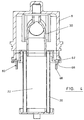
- the assembly of the invention comprises a housing 2 and a filter element 4.
- the housing consists of a body section 6 and head and base end caps 8, 10.
- the filter element is located wholly within the body section 6 of the housing with the ends of the body section extending beyond the ends of the filter element.
- the head end cap 8 contains an inlet port 12 and an outlet port 14 for a gas that is to be filtered.
- the base end cap 10 can provide a reservoir, and can contain an outlet 16 for liquid that has collected in the assembly. It can conveniently be made from a transparent material so that the level of liquid within it can be inspected. It can include a protective cage 17 for the reservoir.
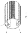
- the filter element 4 comprises a cylindrical wall section 20 formed from a filter medium and top and bottom end fittings 24, 26.
- the wall section defines a cavity 22 within it.
- the material of the filter medium will be selected according to the nature of the gas to be filtered and the material in it that is to be filtered.
- the filter medium will be selected to cause the liquid to coalesce.
- the coalesced liquid within the filter medium will drain through the filter medium and from the filter element.
- Each of the end fittings has a trough 28 formed in it in which the wall section 20 is received and sealed so as to ensure that flow of fluid through the filter element takes place through the filter medium.
- a gas that is to be filtered enters the housing 2 through the inlet port 12 in the head end cap 8 and is directed to the internal cavity 22 within the filter medium by means of a flow conduit 30.
- the gas flows outwardly through the filter medium. Any liquid in the gas stream can be coalesced within the filter medium. Any solid particles within the gas stream can also be collected by the filter element.
- Gas that has passed through the filter medium is discharged from the assembly through the outlet port 14 in the head end cap 8.
- connections to the housing end cap for the flow of fluid can be made by means of an adaptor block 90 which can be fitted to the housing head end cap 8 and which bears appropriate formations to make a secure connection to a conduit for the fluid to be filtered or other component.
- the flow conduit 30, by which the flow of gas between the inlet port 12 in the head end cap and the internal cavity 22 within filter medium 20 is directed, is located within the head end cap 8.
- the flow conduit 30 has a first conduit opening 32 which is sealed to the inlet port 12, and a second conduit opening 34 which communicates with the internal cavity 22 within the filter medium. In the illustrated embodiment, the angle between the axes of the two openings is about 90°.
- the flow conduit 30 is gently curved and presents a smooth flow path for a gas stream flowing between the two openings.
- the flow conduit has a port 40 in it for connection to a gauge for measuring the differential pressure across the filter element.
- the flow conduit 30 can be formed with its curved shape and integral port and other features by a moulding process, especially when it is formed from polymeric material.
- the flow conduit can be formed as a one-piece moulding with the top end fitting 24 of the filter element 4.
- the inlet port 12 in the head end cap and the corresponding face of the flow conduit present mating planar internal surfaces 44, 46.
- the opposite edges of the surface 46 on the flow conduit present a pair of ribs 48 which are received between a corresponding pair of ribs 50 presented by the surface 44 on the end cap to retain the sealing surfaces in contact with one another.
- the ribs 48 on the flow conduit and the ribs 50 on the end cap are aligned with the axis along which the flow conduit is introduced into the housing end cap so that the two sets of ribs engage one another as the flow conduit is introduced.
- the ribs are tapered so that they have a wedge shape when viewed from the side to ensure that the mating sealing surfaces 44, 46 on the flow conduit and the housing head end cap are forced together as the flow conduit is introduced into the end cap, to enhance the seal between the surfaces.
- the taper on the ribs 48 on the flow conduit can be seen in particular in Figure 3.
- a sealing gasket 53 is provided in a groove on the surface 46 of the flow conduit around the first conduit opening 32, which is compressed between that surface and the surface 44 on the end cap.
- the port 40 for connection to a differential pressure gauge can be received in a downwardly facing socket in the end cap, forming a seal by compression of a gasket between the internal surface of the socket and the external surface of the port.
- the flow conduit 30 bears two downwardly extending deformable tangs 60.
- Each tang has an outwardly projecting limb 62 which can be received in a slot 64 in the housing end cap 8 when the flow conduit is properly located in the end cap, as shown in Figure 4.
- Location of the limb 62 in the slot 64 is facilitated by a tapered ramp 66 to the slot, causing the tang to be deformed inwardly before springing back into the slot.
- Location of the tang in the slot can be detected by the operator by feel.
- the slot can be open so that location of the tang in the slot can be detected by visual inspection.
- the limb can retain the flow conduit within the end cap, at least until other components of the assembly have been introduced.
- the tang 60 also includes a downwardly extending projection 68 by which the tang can be deformed inwardly to release the limb 62 from the slot, allowing the flow conduit to be released from the end cap.
- the bottom end fitting 26 includes three transversely extending limbs 70 which extend between the filter medium 20 and the internal wall of the housing.
- the limbs engage a support surface in the form of an upwardly facing ledge 72 on the base end cap 10 of the housing.
- connection between the head end cap 8 and the body section 6 of the housing can be made by a bayonet arrangement in which four orthogonally arranged lugs 80 on the end cap which are received in transverse grooves within the body section.
- each groove 82 is formed in one of four longitudinally extending ribs 84.
- a detent 86 on at least some of the lugs 80 can retain the lugs and grooves together, preventing inadvertent rotation which would release the end cap from the body section.
- a similar arrangement of lugs and grooves can be used to form a connection between the base end cap and the body section.
Landscapes
- Chemical & Material Sciences (AREA)
- Chemical Kinetics & Catalysis (AREA)
- Physics & Mathematics (AREA)
- Geometry (AREA)
- Filtering Of Dispersed Particles In Gases (AREA)
Claims (14)
- Ensemble formant un filtre destiné à recueillir de la matière entraínée dans un courant gazeux, qui comprend un carter (2) d'élément tubulaire de filtre (4), disposé pour que le courant gazeux s'écoule à travers sa paroi, le carter étant doté d'orifices d'entrée et de sortie (12, 14) pour le gaz que l'on doit filtrer, et comprenant un bouchon (8) et une partie formant le corps (6) dans laquelle on loge l'élément constituant le filtre, au moins un des orifices permettant la filtration du gaz se trouvant dans le bouchon, l'ensemble comprenant de plus un dispositif à conduit d'écoulement (30) situé à l'intérieur du bouchon et séparable du bouchon, ensemble dans lequel une première ouverture de conduit (32) est disposée pour communiquer avec l'orifice dans le bouchon et où une seconde ouverture de conduit (34) est disposée pour communiquer avec l'élément constituant le filtre situé dans la partie constituant le corps de carter, ensemble dans lequel l'axe de la première ouverture de conduit et l'axe de la seconde ouverture de conduit ne sont pas alignés, et dans lequel le conduit d'écoulement présente un passage pour écoulement lisse et continu pour l'écoulement du gaz sur sa longueur, entre la première et la seconde ouverture de conduit.
- Ensemble formant un filtre selon la revendication 1, dans lequel l'angle entre l'axe de la première ouverture de conduit et l'axe de la seconde ouverture de conduit vaut au moins 30° environ.
- Ensemble formant un filtre selon la revendication 1, dans lequel l'axe de la première ouverture de conduit est pratiquement perpendiculaire à l'axe de la seconde ouverture de conduit.
- Ensemble formant un filtre selon l'une quelconque des revendications 1 à 3, dans lequel on place le dispositif à conduit d'écoulement dans sa position appropriée à l'intérieur du bouchon grâce à des nervures de raccordement situées sur le conduit d'écoulement et sur le bouchon respectivement.
- Ensemble formant un filtre selon la revendication 4, dans lequel le dispositif à conduit d'écoulement comporte sur lui une bride dont les bords opposés présentent une paire de nervures que l'on place entre une paire correspondante de nervures situées sur le bouchon, afin de retenir le dispositif à l'intérieur du bouchon.
- Ensemble formant un filtre selon la revendication 3 ou selon la revendication 5, dans lequel les nervures sont disposées pour que les nervures qui se trouvent sur le dispositif à conduit d'écoulement aient prise avec les nervures situées sur le bouchon pendant que l'on introduit le dispositif à conduit d'écoulement dans le bouchon.
- Ensemble formant un filtre selon l'une quelconque des revendications 1 à 6, dans lequel le dispositif à conduit d'écoulement est constitué d'un matériau polymère.
- Ensemble formant un filtre selon l'une quelconque des revendications 1 à 7, pour lequel on forme le dispositif à conduit d'écoulement par un procédé de moulage.
- Ensemble formant un filtre selon l'une quelconque des revendications 1 à 8, dans lequel le dispositif à conduit d'écoulement présente à son extrémité une auge, ouverte dans la direction faisant face à l'élément constituant le filtre et dans laquelle on peut placer l'extrémité du milieu tubulaire de filtration.
- Ensemble formant un filtre selon l'une quelconque des revendications 1 à 9, qui contient un élément tubulaire de filtre situé à l'intérieur du carter.
- Ensemble formant un filtre selon la revendication 10, du carter duquel on peut enlever l'élément constituant le filtre, le dispositif à conduit d'écoulement constituant un ensemble d'une seule pièce.
- Ensemble formant un filtre selon l'une quelconque des revendications 1 à 11, dans lequel le carter contient, au niveau de sa seconde extrémité, une sortie pour le liquide entraíné dans le courant gazeux et qui s'accumule dans l'élément constituant le filtre.
- Ensemble formant un filtre selon l'une quelconque des revendications 1 à 12, dans lequel le dispositif à conduit d'écoulement comporte un orifice formé en son sein, destiné au raccord à un moyen qui permet d'indiquer la pression régnant à l'intérieur du conduit.
- Ensemble formant un filtre selon la revendication 13, qui contient un moyen permettant d'indiquer la pression à l'intérieur du conduit d'écoulement, lequel moyen est raccordé audit orifice dans le conduit d'écoulement.
Applications Claiming Priority (7)
| Application Number | Priority Date | Filing Date | Title |
|---|---|---|---|
| GBGB9726415.4A GB9726415D0 (en) | 1997-12-15 | 1997-12-15 | Filter assembly |
| GB9726415 | 1997-12-15 | ||
| GBGB9815959.3A GB9815959D0 (en) | 1998-07-23 | 1998-07-23 | Filter assembly |
| GB9815959 | 1998-07-23 | ||
| GBGB9821700.3A GB9821700D0 (en) | 1998-10-07 | 1998-10-07 | Filter assembly |
| GB9821700 | 1998-10-07 | ||
| PCT/GB1998/003673 WO1999030799A1 (fr) | 1997-12-15 | 1998-12-14 | Ensemble filtre |
Publications (2)
| Publication Number | Publication Date |
|---|---|
| EP1042044A1 EP1042044A1 (fr) | 2000-10-11 |
| EP1042044B1 true EP1042044B1 (fr) | 2004-06-16 |
Family
ID=27269132
Family Applications (1)
| Application Number | Title | Priority Date | Filing Date |
|---|---|---|---|
| EP98961288A Expired - Lifetime EP1042044B1 (fr) | 1997-12-15 | 1998-12-14 | Ensemble filtre |
Country Status (6)
| Country | Link |
|---|---|
| US (1) | US6440201B1 (fr) |
| EP (1) | EP1042044B1 (fr) |
| JP (1) | JP4624553B2 (fr) |
| AU (1) | AU1675099A (fr) |
| DE (1) | DE69824630T2 (fr) |
| WO (1) | WO1999030799A1 (fr) |
Cited By (1)
| Publication number | Priority date | Publication date | Assignee | Title |
|---|---|---|---|---|
| US7618480B2 (en) | 2007-07-16 | 2009-11-17 | Flair Corporation | Filter assembly and method |
Families Citing this family (20)
| Publication number | Priority date | Publication date | Assignee | Title |
|---|---|---|---|---|
| DE69829075T2 (de) * | 1997-12-15 | 2006-01-12 | Domnick Hunter Limited | Filteranlage |
| GB9805655D0 (en) | 1998-03-16 | 1998-05-13 | Celltech Therapeutics Ltd | Chemical compounds |
| DE10052524A1 (de) * | 2000-10-23 | 2002-04-25 | Beko Technologies Gmbh | Filter zum Abscheiden von Fremdstoffen aus einem Gasstrom |
| US7229662B2 (en) * | 2003-12-16 | 2007-06-12 | National University Of Singapore | Heterolayered ferroelectric thin films and methods of forming same |
| GB0417458D0 (en) * | 2004-08-05 | 2004-09-08 | Domnick Hunter Ltd | Filter assembly |
| GB0417462D0 (en) * | 2004-08-05 | 2004-09-08 | Domnick Hunter Ltd | Filter element |
| GB0417464D0 (en) * | 2004-08-05 | 2004-09-08 | Domnick Hunter Ltd | Filter assembly |
| ES2676094T3 (es) * | 2006-06-21 | 2018-07-16 | Donaldson Filtration Deutschland Gmbh | Filtro con pieza de inserción reemplazable |
| EP1967247B1 (fr) * | 2007-03-02 | 2012-09-05 | Kaeser Kompressoren AG | Filtre à air comprimé et adapteur adéquat |
| DE102007025809B3 (de) * | 2007-06-02 | 2008-10-16 | Dräger Medical AG & Co. KG | Kohlendioxidabsorber für ein Rückatemsystem |
| WO2010117799A2 (fr) | 2009-03-31 | 2010-10-14 | Donaldson Company, Inc. | Ensembles filtres pour liquides, caractéristiques, composants et procédés associés |
| DE102011016464B4 (de) | 2011-04-08 | 2016-12-29 | Beko Technologies Gmbh | Strömungsoptimierter Filterkopf |
| SE536415C2 (sv) * | 2012-03-01 | 2013-10-15 | Scania Cv Ab | Filterhus och filterenhet |
| US9849413B2 (en) | 2012-10-10 | 2017-12-26 | Ingersoll-Rand Company | Upper end cap for filter |
| EP2906325B1 (fr) | 2012-10-10 | 2019-05-08 | Ingersoll-Rand Company | Adaptateur d'élément de filtre pour filtre à air comprimé |
| EP2848297B1 (fr) * | 2013-09-03 | 2016-11-02 | Walker Filtration Limited | Ensemble de filtre et élément de filtre pour un tel ensemble |
| GB2520770A (en) * | 2013-12-02 | 2015-06-03 | Nano Porous Solutions Ltd | An end cap for a filter assembly |
| DE202013105569U1 (de) | 2013-12-06 | 2014-01-28 | Beko Technologies Gmbh | Filterelement mit Strömungsleitkörper |
| JP6370251B2 (ja) * | 2015-03-26 | 2018-08-08 | 株式会社コガネイ | エレメント組立体およびフィルタ |
| DE102016013588A1 (de) * | 2016-11-09 | 2018-05-09 | Hydac Filtertechnik Gmbh | Filtervorrichtung |
Citations (2)
| Publication number | Priority date | Publication date | Assignee | Title |
|---|---|---|---|---|
| GB2126497A (en) * | 1982-09-09 | 1984-03-28 | Domnick Hunter Filters Ltd | Coalescing filter element |
| US4516994A (en) * | 1984-04-11 | 1985-05-14 | Vilter Manufacturing Corporation | Apparatus for separating liquid droplets from gas |
Family Cites Families (39)
| Publication number | Priority date | Publication date | Assignee | Title |
|---|---|---|---|---|
| US428307A (en) * | 1890-05-20 | Steam-muffler | ||
| US780682A (en) * | 1903-09-21 | 1905-01-24 | Joseph Posch | Combined trap, filter, and air-distributer. |
| US1091695A (en) * | 1913-06-14 | 1914-03-31 | Anheuser Busch Brewing Ass | Air-filter. |
| US2606628A (en) * | 1947-10-25 | 1952-08-12 | Claude F Hasselwander | Filter |
| US3675776A (en) | 1970-12-16 | 1972-07-11 | Philip Campo | Filter device |
| US4063913A (en) | 1974-08-26 | 1977-12-20 | Becton, Dickinson And Company | Bacteria filters with transparent housings |
| DE7706092U1 (de) | 1977-02-28 | 1977-06-30 | Ultrafilter Gmbh, 4000 Duesseldorf | Filtergehaeuse |
| US4149974A (en) | 1977-04-01 | 1979-04-17 | Carrier Corporation | Strainer apparatus mounted within a tube |
| US4544387A (en) * | 1983-09-21 | 1985-10-01 | Agerlid Charles G | Outer to inner flow vacuum filter with see through outer enclosure |
| DE3541370A1 (de) | 1984-11-23 | 1986-05-28 | Domnick Hunter Filters Ltd., Birtley, Co. Durham | Fluessigkeits/gas-abscheider |
| US4608166A (en) | 1985-04-01 | 1986-08-26 | Filtertek, Inc. | Press fit filter |
| JPH0113539Y2 (fr) * | 1985-04-06 | 1989-04-20 | ||
| US4774853A (en) * | 1985-04-16 | 1988-10-04 | Smc Kabushiki Kaisha | Case mounting mechanism for use with pneumatic apparatus |
| JPH0215540Y2 (fr) * | 1985-04-16 | 1990-04-26 | ||
| JPH0729003B2 (ja) | 1986-01-27 | 1995-04-05 | キユノ、インコ−ポレ−テツド | 濾過装置及びその濾過容器 |
| JPS6339414U (fr) * | 1986-08-29 | 1988-03-14 | ||
| DE3702205A1 (de) | 1987-01-26 | 1988-08-04 | Deutsche Filterbau | Staubdichte befestigung von filterelementen in einem filterbehaelter fuer die entstaubung von insbesondere unter hoeherem druck stehenden heissgasen |
| GB8703313D0 (en) | 1987-02-13 | 1987-03-18 | Process Scient Innovations | Coupling |
| SE467471B (sv) | 1987-02-16 | 1992-07-20 | Stenhex Ab | Anordning foer filtrering och vaermevaexling |
| JPH0729004B2 (ja) * | 1988-02-01 | 1995-04-05 | 富士写真フイルム株式会社 | 止め弁付フイルタ装置 |
| GB2222534B (en) | 1988-09-09 | 1992-11-25 | Process Scient Innovations | Filter assembly and cartridge therefor |
| GB2250454B (en) | 1988-09-16 | 1993-03-03 | Atomic Energy Authority Uk | Air filter |
| JPH0538819Y2 (fr) * | 1989-01-17 | 1993-09-30 | ||
| DE3909402A1 (de) | 1989-03-22 | 1990-09-27 | Schumacher Gmbh & Co Kg | Filter fuer gasfoermige medien |
| JPH0733145Y2 (ja) * | 1989-09-30 | 1995-07-31 | 株式会社前田シェルサービス | 差圧インジケータ |
| JPH0437519U (fr) * | 1990-07-28 | 1992-03-30 | ||
| GB2261830B (en) | 1991-11-26 | 1995-07-26 | Process Scient Innovations | Filter for purification of gas |
| ATE184502T1 (de) | 1991-12-17 | 1999-10-15 | Mann & Hummel Filter | Filter für kraft- und/oder schmierstoffe eines verbrennungsmotors |
| JPH0611824U (ja) * | 1992-07-04 | 1994-02-15 | 株式会社堀場製作所 | ミストセパレータ |
| US5395509A (en) | 1992-07-06 | 1995-03-07 | Valycontrol S.A. De C.V. | Container for a refrigerant system filter |
| AU660816B2 (en) * | 1992-07-07 | 1995-07-06 | Sweepy International S.A. | Filter |
| JPH0621717U (ja) * | 1992-08-20 | 1994-03-22 | エスエムシー株式会社 | 複合エアフィルタ |
| JPH06178910A (ja) * | 1992-12-11 | 1994-06-28 | Tsutomu Kamata | 圧縮空気除湿装置 |
| SE500893C2 (sv) | 1993-02-10 | 1994-09-26 | Sunds Defibrator Ind Ab | Trycksilanordning |
| JPH07328364A (ja) * | 1994-04-13 | 1995-12-19 | Koganei Corp | ドレン捕集フィルタおよびその製造方法 |
| JPH10512798A (ja) | 1994-10-21 | 1998-12-08 | ポール コーポレイション | 流体処理装置 |
| GB2295970A (en) | 1994-12-16 | 1996-06-19 | Process Scient Innovations | Filter assembly and cartridge therefor |
| EP0752262A1 (fr) | 1995-07-07 | 1997-01-08 | Flair Corporation | Attachement d'une couche de drainage d'un filtre |
| DE19642641C2 (de) | 1995-11-27 | 1998-03-19 | Knecht Filterwerke Gmbh | Kunststoff-Schraubdeckel in Glockenform für ein Filtergehäuse |
-
1998
- 1998-12-14 AU AU16750/99A patent/AU1675099A/en not_active Abandoned
- 1998-12-14 EP EP98961288A patent/EP1042044B1/fr not_active Expired - Lifetime
- 1998-12-14 JP JP2000538771A patent/JP4624553B2/ja not_active Expired - Lifetime
- 1998-12-14 DE DE69824630T patent/DE69824630T2/de not_active Expired - Lifetime
- 1998-12-14 WO PCT/GB1998/003673 patent/WO1999030799A1/fr active IP Right Grant
- 1998-12-14 US US09/581,321 patent/US6440201B1/en not_active Expired - Lifetime
Patent Citations (2)
| Publication number | Priority date | Publication date | Assignee | Title |
|---|---|---|---|---|
| GB2126497A (en) * | 1982-09-09 | 1984-03-28 | Domnick Hunter Filters Ltd | Coalescing filter element |
| US4516994A (en) * | 1984-04-11 | 1985-05-14 | Vilter Manufacturing Corporation | Apparatus for separating liquid droplets from gas |
Cited By (3)
| Publication number | Priority date | Publication date | Assignee | Title |
|---|---|---|---|---|
| US7618480B2 (en) | 2007-07-16 | 2009-11-17 | Flair Corporation | Filter assembly and method |
| US7828881B2 (en) | 2007-07-16 | 2010-11-09 | Flair Corporation | Filter assembly and method |
| USRE44424E1 (en) | 2007-07-16 | 2013-08-13 | Spx Flow Technology Usa, Inc. | Filter assembly and method |
Also Published As
| Publication number | Publication date |
|---|---|
| US6440201B1 (en) | 2002-08-27 |
| DE69824630T2 (de) | 2005-06-23 |
| EP1042044A1 (fr) | 2000-10-11 |
| DE69824630D1 (de) | 2004-07-22 |
| AU1675099A (en) | 1999-07-05 |
| JP4624553B2 (ja) | 2011-02-02 |
| JP2002508237A (ja) | 2002-03-19 |
| WO1999030799A1 (fr) | 1999-06-24 |
Similar Documents
| Publication | Publication Date | Title |
|---|---|---|
| EP1042044B1 (fr) | Ensemble filtre | |
| EP1042046B1 (fr) | Ensemble filtre | |
| EP1042045B1 (fr) | Ensemble filtre | |
| EP1042043B1 (fr) | Systeme de filtre | |
| US6663685B2 (en) | Filter assembly | |
| EP1042047B1 (fr) | Ensemble filtre | |
| EP1210164B1 (fr) | Filtre a huile avec tube central a fixation par pression integree | |
| CN1315559C (zh) | 具有容易更换特征的可拆卸流体分离装置和歧管设计 | |
| US20180154294A1 (en) | Dripless filter assembly and method for servicing a filtration apparatus with the same | |
| US20070227963A1 (en) | Fluid filter element and bypass adaptor | |
| US8349061B2 (en) | Combination relief valve and drainage mechanism requiring inserted element to permit drainage in a coalescer system | |
| EP2282918A1 (fr) | Reniflard pour système de fluide hydraulique, avec voies d écoulement d air d'admission et de sortie indépendantes | |
| US10675567B2 (en) | Filter element assembly | |
| US20030094405A1 (en) | Low waste liquid filter | |
| WO1999030803A1 (fr) | Ensemble filtre | |
| EP1576997B1 (fr) | Conception d'ensemble jetable à dispositif de séparation de fluides et à collecteur susceptible d'être remplacé facilement | |
| WO1998052676A1 (fr) | Element filtrant a covalescence | |
| CN210409950U (zh) | 过滤设备 | |
| GB2408223A (en) | A filter assembly | |
| US7097693B1 (en) | Combination depth and phase separation membrane filter |
Legal Events
| Date | Code | Title | Description |
|---|---|---|---|
| PUAI | Public reference made under article 153(3) epc to a published international application that has entered the european phase |
Free format text: ORIGINAL CODE: 0009012 |
|
| 17P | Request for examination filed |
Effective date: 20000705 |
|
| AK | Designated contracting states |
Kind code of ref document: A1 Designated state(s): DE FR GB IT SE |
|
| 17Q | First examination report despatched |
Effective date: 20020118 |
|
| GRAP | Despatch of communication of intention to grant a patent |
Free format text: ORIGINAL CODE: EPIDOSNIGR1 |
|
| GRAS | Grant fee paid |
Free format text: ORIGINAL CODE: EPIDOSNIGR3 |
|
| GRAA | (expected) grant |
Free format text: ORIGINAL CODE: 0009210 |
|
| AK | Designated contracting states |
Kind code of ref document: B1 Designated state(s): DE FR GB IT SE |
|
| REG | Reference to a national code |
Ref country code: GB Ref legal event code: FG4D |
|
| REF | Corresponds to: |
Ref document number: 69824630 Country of ref document: DE Date of ref document: 20040722 Kind code of ref document: P |
|
| PG25 | Lapsed in a contracting state [announced via postgrant information from national office to epo] |
Ref country code: SE Free format text: LAPSE BECAUSE OF FAILURE TO SUBMIT A TRANSLATION OF THE DESCRIPTION OR TO PAY THE FEE WITHIN THE PRESCRIBED TIME-LIMIT Effective date: 20040916 |
|
| ET | Fr: translation filed | ||
| PLBE | No opposition filed within time limit |
Free format text: ORIGINAL CODE: 0009261 |
|
| STAA | Information on the status of an ep patent application or granted ep patent |
Free format text: STATUS: NO OPPOSITION FILED WITHIN TIME LIMIT |
|
| 26N | No opposition filed |
Effective date: 20050317 |
|
| PG25 | Lapsed in a contracting state [announced via postgrant information from national office to epo] |
Ref country code: IT Free format text: LAPSE BECAUSE OF NON-PAYMENT OF DUE FEES;WARNING: LAPSES OF ITALIAN PATENTS WITH EFFECTIVE DATE BEFORE 2007 MAY HAVE OCCURRED AT ANY TIME BEFORE 2007. THE CORRECT EFFECTIVE DATE MAY BE DIFFERENT FROM THE ONE RECORDED. Effective date: 20051214 |
|
| REG | Reference to a national code |
Ref country code: GB Ref legal event code: 732E |
|
| REG | Reference to a national code |
Ref country code: FR Ref legal event code: TP |
|
| REG | Reference to a national code |
Ref country code: FR Ref legal event code: PLFP Year of fee payment: 18 |
|
| REG | Reference to a national code |
Ref country code: FR Ref legal event code: PLFP Year of fee payment: 19 |
|
| REG | Reference to a national code |
Ref country code: FR Ref legal event code: PLFP Year of fee payment: 20 |
|
| PGFP | Annual fee paid to national office [announced via postgrant information from national office to epo] |
Ref country code: FR Payment date: 20171227 Year of fee payment: 20 |
|
| PGFP | Annual fee paid to national office [announced via postgrant information from national office to epo] |
Ref country code: GB Payment date: 20171227 Year of fee payment: 20 |
|
| PGFP | Annual fee paid to national office [announced via postgrant information from national office to epo] |
Ref country code: DE Payment date: 20171229 Year of fee payment: 20 |
|
| REG | Reference to a national code |
Ref country code: DE Ref legal event code: R071 Ref document number: 69824630 Country of ref document: DE |
|
| REG | Reference to a national code |
Ref country code: GB Ref legal event code: PE20 Expiry date: 20181213 |
|
| PG25 | Lapsed in a contracting state [announced via postgrant information from national office to epo] |
Ref country code: GB Free format text: LAPSE BECAUSE OF EXPIRATION OF PROTECTION Effective date: 20181213 |