EP1041131A1 - Double faced tape, method of and apparatus for manufacturing same - Google Patents
Double faced tape, method of and apparatus for manufacturing same Download PDFInfo
- Publication number
- EP1041131A1 EP1041131A1 EP98901090A EP98901090A EP1041131A1 EP 1041131 A1 EP1041131 A1 EP 1041131A1 EP 98901090 A EP98901090 A EP 98901090A EP 98901090 A EP98901090 A EP 98901090A EP 1041131 A1 EP1041131 A1 EP 1041131A1
- Authority
- EP
- European Patent Office
- Prior art keywords
- tape
- adhesive matrix
- cutter
- double
- raw
- Prior art date
- Legal status (The legal status is an assumption and is not a legal conclusion. Google has not performed a legal analysis and makes no representation as to the accuracy of the status listed.)
- Withdrawn
Links
Images


Classifications
-
- B—PERFORMING OPERATIONS; TRANSPORTING
- B26—HAND CUTTING TOOLS; CUTTING; SEVERING
- B26D—CUTTING; DETAILS COMMON TO MACHINES FOR PERFORATING, PUNCHING, CUTTING-OUT, STAMPING-OUT OR SEVERING
- B26D1/00—Cutting through work characterised by the nature or movement of the cutting member or particular materials not otherwise provided for; Apparatus or machines therefor; Cutting members therefor
- B26D1/01—Cutting through work characterised by the nature or movement of the cutting member or particular materials not otherwise provided for; Apparatus or machines therefor; Cutting members therefor involving a cutting member which does not travel with the work
- B26D1/12—Cutting through work characterised by the nature or movement of the cutting member or particular materials not otherwise provided for; Apparatus or machines therefor; Cutting members therefor involving a cutting member which does not travel with the work having a cutting member moving about an axis
- B26D1/14—Cutting through work characterised by the nature or movement of the cutting member or particular materials not otherwise provided for; Apparatus or machines therefor; Cutting members therefor involving a cutting member which does not travel with the work having a cutting member moving about an axis with a circular cutting member, e.g. disc cutter
- B26D1/22—Cutting through work characterised by the nature or movement of the cutting member or particular materials not otherwise provided for; Apparatus or machines therefor; Cutting members therefor involving a cutting member which does not travel with the work having a cutting member moving about an axis with a circular cutting member, e.g. disc cutter coacting with a movable member, e.g. a roller
- B26D1/225—Cutting through work characterised by the nature or movement of the cutting member or particular materials not otherwise provided for; Apparatus or machines therefor; Cutting members therefor involving a cutting member which does not travel with the work having a cutting member moving about an axis with a circular cutting member, e.g. disc cutter coacting with a movable member, e.g. a roller for thin material, e.g. for sheets, strips or the like
-
- B—PERFORMING OPERATIONS; TRANSPORTING
- B26—HAND CUTTING TOOLS; CUTTING; SEVERING
- B26D—CUTTING; DETAILS COMMON TO MACHINES FOR PERFORATING, PUNCHING, CUTTING-OUT, STAMPING-OUT OR SEVERING
- B26D11/00—Combinations of several similar cutting apparatus
-
- B—PERFORMING OPERATIONS; TRANSPORTING
- B26—HAND CUTTING TOOLS; CUTTING; SEVERING
- B26D—CUTTING; DETAILS COMMON TO MACHINES FOR PERFORATING, PUNCHING, CUTTING-OUT, STAMPING-OUT OR SEVERING
- B26D3/00—Cutting work characterised by the nature of the cut made; Apparatus therefor
- B26D3/08—Making a superficial cut in the surface of the work without removal of material, e.g. scoring, incising
- B26D3/085—On sheet material
-
- B—PERFORMING OPERATIONS; TRANSPORTING
- B26—HAND CUTTING TOOLS; CUTTING; SEVERING
- B26D—CUTTING; DETAILS COMMON TO MACHINES FOR PERFORATING, PUNCHING, CUTTING-OUT, STAMPING-OUT OR SEVERING
- B26D9/00—Cutting apparatus combined with punching or perforating apparatus or with dissimilar cutting apparatus
-
- C—CHEMISTRY; METALLURGY
- C09—DYES; PAINTS; POLISHES; NATURAL RESINS; ADHESIVES; COMPOSITIONS NOT OTHERWISE PROVIDED FOR; APPLICATIONS OF MATERIALS NOT OTHERWISE PROVIDED FOR
- C09J—ADHESIVES; NON-MECHANICAL ASPECTS OF ADHESIVE PROCESSES IN GENERAL; ADHESIVE PROCESSES NOT PROVIDED FOR ELSEWHERE; USE OF MATERIALS AS ADHESIVES
- C09J7/00—Adhesives in the form of films or foils
- C09J7/10—Adhesives in the form of films or foils without carriers
-
- C—CHEMISTRY; METALLURGY
- C09—DYES; PAINTS; POLISHES; NATURAL RESINS; ADHESIVES; COMPOSITIONS NOT OTHERWISE PROVIDED FOR; APPLICATIONS OF MATERIALS NOT OTHERWISE PROVIDED FOR
- C09J—ADHESIVES; NON-MECHANICAL ASPECTS OF ADHESIVE PROCESSES IN GENERAL; ADHESIVE PROCESSES NOT PROVIDED FOR ELSEWHERE; USE OF MATERIALS AS ADHESIVES
- C09J7/00—Adhesives in the form of films or foils
- C09J7/20—Adhesives in the form of films or foils characterised by their carriers
- C09J7/22—Plastics; Metallised plastics
-
- C—CHEMISTRY; METALLURGY
- C09—DYES; PAINTS; POLISHES; NATURAL RESINS; ADHESIVES; COMPOSITIONS NOT OTHERWISE PROVIDED FOR; APPLICATIONS OF MATERIALS NOT OTHERWISE PROVIDED FOR
- C09J—ADHESIVES; NON-MECHANICAL ASPECTS OF ADHESIVE PROCESSES IN GENERAL; ADHESIVE PROCESSES NOT PROVIDED FOR ELSEWHERE; USE OF MATERIALS AS ADHESIVES
- C09J7/00—Adhesives in the form of films or foils
- C09J7/30—Adhesives in the form of films or foils characterised by the adhesive composition
- C09J7/38—Pressure-sensitive adhesives [PSA]
-
- B—PERFORMING OPERATIONS; TRANSPORTING
- B32—LAYERED PRODUCTS
- B32B—LAYERED PRODUCTS, i.e. PRODUCTS BUILT-UP OF STRATA OF FLAT OR NON-FLAT, e.g. CELLULAR OR HONEYCOMB, FORM
- B32B38/00—Ancillary operations in connection with laminating processes
- B32B38/10—Removing layers, or parts of layers, mechanically or chemically
-
- C—CHEMISTRY; METALLURGY
- C09—DYES; PAINTS; POLISHES; NATURAL RESINS; ADHESIVES; COMPOSITIONS NOT OTHERWISE PROVIDED FOR; APPLICATIONS OF MATERIALS NOT OTHERWISE PROVIDED FOR
- C09J—ADHESIVES; NON-MECHANICAL ASPECTS OF ADHESIVE PROCESSES IN GENERAL; ADHESIVE PROCESSES NOT PROVIDED FOR ELSEWHERE; USE OF MATERIALS AS ADHESIVES
- C09J2301/00—Additional features of adhesives in the form of films or foils
- C09J2301/10—Additional features of adhesives in the form of films or foils characterized by the structural features of the adhesive tape or sheet
- C09J2301/12—Additional features of adhesives in the form of films or foils characterized by the structural features of the adhesive tape or sheet by the arrangement of layers
- C09J2301/124—Additional features of adhesives in the form of films or foils characterized by the structural features of the adhesive tape or sheet by the arrangement of layers the adhesive layer being present on both sides of the carrier, e.g. double-sided adhesive tape
-
- C—CHEMISTRY; METALLURGY
- C09—DYES; PAINTS; POLISHES; NATURAL RESINS; ADHESIVES; COMPOSITIONS NOT OTHERWISE PROVIDED FOR; APPLICATIONS OF MATERIALS NOT OTHERWISE PROVIDED FOR
- C09J—ADHESIVES; NON-MECHANICAL ASPECTS OF ADHESIVE PROCESSES IN GENERAL; ADHESIVE PROCESSES NOT PROVIDED FOR ELSEWHERE; USE OF MATERIALS AS ADHESIVES
- C09J2301/00—Additional features of adhesives in the form of films or foils
- C09J2301/10—Additional features of adhesives in the form of films or foils characterized by the structural features of the adhesive tape or sheet
- C09J2301/18—Additional features of adhesives in the form of films or foils characterized by the structural features of the adhesive tape or sheet characterized by perforations in the adhesive tape
-
- C—CHEMISTRY; METALLURGY
- C09—DYES; PAINTS; POLISHES; NATURAL RESINS; ADHESIVES; COMPOSITIONS NOT OTHERWISE PROVIDED FOR; APPLICATIONS OF MATERIALS NOT OTHERWISE PROVIDED FOR
- C09J—ADHESIVES; NON-MECHANICAL ASPECTS OF ADHESIVE PROCESSES IN GENERAL; ADHESIVE PROCESSES NOT PROVIDED FOR ELSEWHERE; USE OF MATERIALS AS ADHESIVES
- C09J2301/00—Additional features of adhesives in the form of films or foils
- C09J2301/30—Additional features of adhesives in the form of films or foils characterized by the chemical, physicochemical or physical properties of the adhesive or the carrier
- C09J2301/302—Additional features of adhesives in the form of films or foils characterized by the chemical, physicochemical or physical properties of the adhesive or the carrier the adhesive being pressure-sensitive, i.e. tacky at temperatures inferior to 30°C
-
- Y—GENERAL TAGGING OF NEW TECHNOLOGICAL DEVELOPMENTS; GENERAL TAGGING OF CROSS-SECTIONAL TECHNOLOGIES SPANNING OVER SEVERAL SECTIONS OF THE IPC; TECHNICAL SUBJECTS COVERED BY FORMER USPC CROSS-REFERENCE ART COLLECTIONS [XRACs] AND DIGESTS
- Y10—TECHNICAL SUBJECTS COVERED BY FORMER USPC
- Y10T—TECHNICAL SUBJECTS COVERED BY FORMER US CLASSIFICATION
- Y10T156/00—Adhesive bonding and miscellaneous chemical manufacture
- Y10T156/10—Methods of surface bonding and/or assembly therefor
- Y10T156/1052—Methods of surface bonding and/or assembly therefor with cutting, punching, tearing or severing
-
- Y—GENERAL TAGGING OF NEW TECHNOLOGICAL DEVELOPMENTS; GENERAL TAGGING OF CROSS-SECTIONAL TECHNOLOGIES SPANNING OVER SEVERAL SECTIONS OF THE IPC; TECHNICAL SUBJECTS COVERED BY FORMER USPC CROSS-REFERENCE ART COLLECTIONS [XRACs] AND DIGESTS
- Y10—TECHNICAL SUBJECTS COVERED BY FORMER USPC
- Y10T—TECHNICAL SUBJECTS COVERED BY FORMER US CLASSIFICATION
- Y10T428/00—Stock material or miscellaneous articles
- Y10T428/28—Web or sheet containing structurally defined element or component and having an adhesive outermost layer
Definitions
- the present invention concerns a double-coated coated tape, in which an adhesive matrix is overlaid on only the central part in the width direction of a band-shaped separator of what is generally called release paper or release film of predetermined width and in which an adhesive matrix is not provided on the left and right edge portions of the band-shaped separator, a method of manufacturing the same tape, and a device for manufacturing the same tape.
- a tape body with which an adhesive matrix 2 is overlaid on the entire surface at one side of a band-shaped separator 1 of predetermined width is wound into a coil so that the adhesive matrix 2 side will be at the inner side as shown in Fig. 8.
- the double-coated tape body which has been drawn out from the coil body as indicated by the arrow in Fig. 8 and cut to a certain length, is adhered with the adhesive matrix 2 side facing the adherend 3 as shown in Fig. 9.
- tweezers are used or fingertips are used directly to peel separator 1 so that only adhesive matrix 2 will be left on adherend 3 and another unillustrated member is adhered onto adhesive matrix 2, which is exposed on adherend 3.
- the coil-form double-coated tape shown in Fig. 8 is manufactured by cutting (slicing) or slitting, as shown by the hypothetical lines in Fig. 10, a raw-fabric tape 5, that has been arranged by winding a wide, band-shaped tape body, with which an adhesive matrix is overlaid on one surface of a separator, into a roll so that the adhesive matrix side will be at the inner side.
- an arrangement that guides edge parts of the drawn-out, double-coated tape body 1 to the predetermined position by means of a guide member 8, is essential.
- the adhesive matrix 2 that is exposed at the edge parts of the double-coated tape body contacts guide member 8 to obstruct smooth conveying of the double-coated tape body. It was thus difficult to draw out the double-coated tape body and position it accurately onto an appropriate position in the width direction.
- the present invention has been made in view of the above problems of the prior art and the first object thereof is to present a double-coated tape with which the separator can be peeled easily by providing the adhesive matrix only at the central part in the width direction of the separator.
- the second and third objects of the present invention are to present a method and device for manufacturing a double-coated tape with which the adhesive matrix is provided only at the central part in the width direction of the separator.
- the First Claim of the present invention provides in a double-coated tape, with which a double-coated tape body, arranged by overlaying an adhesive matrix on one surface of a band-shaped separator of predetermined width, is wound into a coil so that the adhesive matrix side will be at the inner side, a double-coated tape in which the adhesive matrix is provided so as to leave the portions near the left and right edges of the separator free of the adhesive matrix.
- the left and right edge portions of the separator can be picked up readily with fingers or tweezers and the separator can thus be peeled off readily from the adhesive matrix layer that is adhered onto the adherend.
- the adhesive matrix is not exposed at the side edge portions of the double-coated tape body, the side faces of the coil-form double-coated tape will not be sticky, making the handling and storage of the double-coated tape easy.
- the double-coated tape can be drawn out or conveyed smoothly even in an arrangement where the side edge portions of a double-coated tape body that has been drawn out from the coil-form double-coated tape is guided by a guide member.
- the Second Claim of the present invention provides a method of manufacturing double-coated tape comprising the steps of unwinding and conveying a raw-fabric tape, which has been arranged by winding into a roll a raw-fabric tape body with which an adhesive matrix has been overlaid on one surface of a wide, band-shaped separator, using a tape cutter to cut the conveyed raw-fabric tape body into a plurality of bands, that extend along the conveying direction, using an adhesive matrix cutter to cut the central part in the width direction of the adhesive matrix layer of each of the cut band-shaped tape bodies to a predetermined width, using an adhesive matrix windup shaft to wind up and thereby remove the thin, cord-like, side edge trimmings of the adhesive matrix layer that have been cut, and using a tape windup shaft to wind up and thereby forming into a coil the band-shaped tape body on which the adhesive matrix is overlaid only at the central part in the width direction.
- the tape cutter and the adhesive matrix cutter in the method of manufacturing double-coated tape of the Second Claim are arranged to be made integral to perform the cutting of the raw-fabric tape body (separator and adhesive matrix layer) by the tape cutter and the cutting of the adhesive matrix layer by the adhesive matrix cutter at the same time.
- the Fourth Claim of the present invention presents a double-coated tape manufacturing device comprised of a raw-fabric tape shaft, which fittingly supports a raw-fabric tape, which is arranged by winding a double-coated tape body, in which an adhesive matrix is overlaid on one surface of a wide, band-shaped separator, into a roll with the adhesive matrix side at the inner side, and unwinds and feeds out the roll-form raw-fabric tape,
- a plurality of coil-form, double-coated tapes, in which the adhesive matrix is overlaid only on the central part in the width direction of the separator, can thus be manufactured with an extremely simple device structure comprised of a raw-fabric tape shaft, a tape and adhesive matrix cutter, an adhesive matrix windup shaft, and a tape windup shaft.
- guide rolls for controlling the direction of the conveying of the tape body are provided in the tape body conveying path between the raw-fabric tape shaft and tape windup shaft of the double-coated tape manufacturing device of the Fourth Claim.
- the degree of freedom of layout of the raw-fabric tape shaft, tape and adhesive matrix cutter, adhesive matrix windup shaft, and tape windup shaft in the device is increased.
- the tape and adhesive matrix cutter of the double-coated tape manufacturing device of the Fourth Claim is comprised of
- the raw-fabric tape body In the process of being cut by the rotating blades, the raw-fabric tape body is held in a manner whereby the rear surface side (the side on which the adhesive matrix layer is not formed) thereof is pressed against the outer peripheral surface of the base roll and the cutting position of the raw-fabric tape body is thus prevented from varying (becoming dispersed) in the width direction of the raw-fabric tape body.
- the separator cutting rotating blades, that co-act with the base roll and comprise the tape cutter, and the adhesive matrix cutting rotating blades, that co-act with the base roll and comprise the adhesive matrix cutter, are integrated coaxially as a cutter roll, making the tape and adhesive matrix cutter compact.
- the raw-fabric tape body is cut into bands and, at the same time, just the central part in the width direction of the adhesive matrix layer of each band-shaped tape body that has been cut is cut further to a predetermined width.
- disks that press against the motor-driven base roll are coaxially integrated at both end parts of the cutter roll in the double-coated tape manufacturing device of the Sixth Claim to rotate the cutter roll and base roll synchronously.
- the cutter roll is made to rotate synchronously with and in the direction in reverse of the rotation of the base roll by the disks that are pressed against the motor-driven base roll, there is no need to provide a separate motor for driving the cutter roll.
- the gap between the adhesive matrix cutting rotating blades and the outer peripheral surface of the base roll in the double-coated tape manufacturing device of the sixth or Seventh Claim is set equivalent to the thickness of the separator.
- the adhesive matrix cutting rotating blades will thus cut just the adhesive matrix layer overlaid on the separator without flawing the separator.
- the gap between the adhesive matrix cutting rotating blades and the outer peripheral surface of the base roll in the double-coated tape manufacturing device of the sixth or Seventh Claim is set to be slightly smaller than the thickness of the separator.
- the adhesive matrix cutting rotating blades are thus made to penetrate to the surface layer part of the separator below the adhesive matrix layer of the tape body that has been cut so that the adhesive matrix layer will be cut without fail.
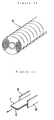
- Figs. 1 through 6 show an embodiment of the present invention with Fig. 1 being a perspective view of a double-coated tape, which is an embodiment of the present invention, Figs. 2(a) and (b) being sectional views of a double-coated tape that has been adhered onto an adherend, Fig. 3 being an overall arrangement diagram of a double-coated tape manufacturing device, Fig. 4 being an enlarged sectional view of the separator and adhesive matrix cutter, which is a principal part of the same device, Fig. 5 being an enlarged sectional view of the tape body that is wound up by the tape windup shaft, and Fig.
- FIG. 6 being perspective views of a double-coated tape that has been manufactured by the same device, with (a) being a perspective view of the condition in which the tape is wound up by the tape windup shaft and (b) being a perspective view of a continuous double-coated tape body from which the trimming coil has been removed.
- symbol 10 indicates a double-coated tape with which a tape body 11, in which an adhesive matrix 14b has been overlaid on one surface of a band-shaped separator 12 of predetermined width (for example, 3mm width), is wound around and made integral in coil-like form with a paper tube 52 of the same width as the separator 12 so that the adhesive matrix 14 (14b) side will be at the inner side.
- Adhesive matrix 14 (14b) is provided so as to leave the edge portions 12a at both sides in the width direction of separator 12 free of the adhesive matrix.
- an adhesive matrix 14 (14b) of a predetermined width (for example, 1.2mm width) is overlaid only on a central part in the width direction of separator 12 and regions of predetermined width (for example, 0.9mm width) along the left and right edge parts 12a of separator 12 are not provided with adhesive matrix 14 (14b).
- edge portions 12a of the separator will be lifted above adherend 3 by just the thickness of adhesive matrix 14b.
- the edge portions 12a of separator 12 can thus be picked up easily with fingers and separator 12 can be peeled off readily to expose adhesive matrix 14b. This is especially effective in the case where an adhesive matrix 14b is to be formed on an adherend 3 at a corner part of a member as shown in Fig. 2(b).
- Examples of the structure of double-coated tape 10 include that in which an adhesive matrix 14, in which an adhesive agent is formed integrally on both surfaces of an unwoven cloth or plastic film, is overlaid on a separator 12, arranged from release paper or release film on which a polyethylene coating or a silicone coating has been applied, and that in which an adhesive matrix 14, made of silicone rubber, is overlaid on a separator 12, formed from polyester film.
- Fig. 3 shows the overall arrangement of a double-sided tape manufacturing device in which a raw-fabric tape 5 (see Fig. 10), arranged by winding into a roll a wide, band-shaped tape body having adhesive matrix 14 overlaid on one surface of separator 12, is processed into a double-coated tape 10, such as that shown in Fig. 1.
- Symbol H indicates the housing of this device.
- a raw-fabric tape shaft 20 which fittingly supports roll-form raw-fabric tape 5 and unwinds roll-form raw-fabric tape 5 and feeds it out as raw-fabric tape body 6, a tape and adhesive matrix cutter 30, which cuts the raw-fabric tape body 6, that has been conveyed from raw-fabric tape shaft 20, into bands of predetermined width along the conveying direction and cuts just the adhesive matrix layer 14 of each of the cut band-shaped tape bodies 11 into three thin, cords in the width direction, an adhesive matrix windup shaft 40, which winds up the thin, cord-like side edge trimmings 14a at the left and right sides in the width direction of the adhesive matrix layer 14 that has been cut, and a tape windup shaft 50, which winds up the band-shaped tape body 11 (see Fig. 5) from which the left and right edge trimmings 14a have been removed by adhesive matrix windup shaft 40 and with which only the adhesive matrix layer 14 (14b) at the central part in the width direction remains, are disposed parallel to each other.
- Raw-fabric tape shaft 20 has a structure that is rotatably supported by a bearing, and roll-form raw-fabric tape 5, which has been fitted onto raw-fabric tape shaft 20 is pulled and unwound naturally by raw-fabric tape body 6 being conveyed by drive rolls 28 and 38 and by the respective band-shaped tape bodies 11, that have been cut at tape and adhesive matrix cutter 30, being wound up by tape windup shaft 50.
- the unwound raw-fabric tape body 6 is guided by guide rolls 24, 25, and 26 and conveyed to tape and adhesive matrix cutter 30.
- Symbol 27 indicates a tension roll and is for maintaining the raw-fabric tape body 6, that is fed to cutter 30, under fixed tension to prevent drooping.
- Symbol M 1 indicates the motor for driving drive rolls 28 and 38. The rotating force of motor M 1 is transmitted to drive rolls 28 and 38 by a belt 29, and raw-fabric tape body 6 is conveyed at a fixed velocity V 1 by the rotation of drive rolls 28 and 38.
- tape and adhesive matrix cutter 30 is comprised of a cutter roll 31, which is a free roll that is disposed in the direction that traverses the conveyed raw-fabric tape body 6, and a metal base roll 38, which is a drive roll that is disposed parallel to cutter roll 31.
- Cutter roll 31 has a structure in which a plurality of tape cutting rotating blades 32, that are disposed parallel to each other with a predetermined spacing provided in between in the axial direction, and pairs of adhesive matrix cutting rotating blades 34, that are, respectively, disposed parallel to each other at the inner side of adjacent tape cutting rotating cutter blades 32, are integrated coaxially, and base roll 38 is disposed so that its outer peripheral surface will be in contact with tape cutting rotating blades 32 of cutter roll 31.
- Disks 35 of the same outer diameter dimension as tape cutting rotating blades 32, are coaxially integrated to the left and right end parts of cutter roll 31, and by these disks 35 being kept pressed against base roll 38, cutter roll 31 is made to rotate in synchronization with and in the direction in reverse of the rotation of base roll 38.
- raw-fabric tape body 6 passes between the rolls 31 and 38 with the adhesive matrix layer 14 side up, it is cut into a plurality of bands (bands of a width equivalent to the distance between tape cutting rotating blades 32) in the width direction (left-to-right direction in Fig. 4) and the adhesive matrix layer 14 of each of the cut band-shaped tape bodies 11 is cut in the width direction into three thin, cords (cut at positions separated from the edge portions of band-shaped tape body 11 by the distance between rotating blades 32 and 34).
- tape cutting rotating blades 32 and base roll 38 of cutter roll 31 comprise a tape cutter A that cuts raw-fabric tape body 6 (separator 12 and adhesive matrix layer 14) into a plurality of bands of predetermined width.
- the adhesive matrix cutting rotating blades 34 and base roll 38 of cutter roll 31 comprise an adhesive matrix cutter B, with which the gap between the outer peripheral surfaces of rotating blades 34 and base roll 38 are set equivalent to the thickness of separator 12 and which cuts just the adhesive matrix layer 14 of each of the cut tape bodies 11 further into three thin, cords in the width direction.
- Tape and adhesive matrix cutter 30 has a structure in which tape cutter A and adhesive matrix cutter B are integrated so that the cutting of raw-fabric tape body 6 by tape cutter A and the cutting of adhesive matrix layer 14 by adhesive matrix cutter B are carried out at the same time.
- the interval between adhesive matrix cutting rotating blades 34 can be set to as small as 0.5mm to make the width of adhesive matrix layer 14b of the double-coated tape shown in Fig. 1 a narrow width of 0.5mm.
- the gap between the abovementioned adhesive matrix cutting blades rotating 34 and the outer peripheral surface of base roll 38 is set a few microns smaller than the thickness of separator body 12 so that the edges of rotating blades 34 will penetrate to the surface layer portion of separator body 12 below adhesive matrix layer 14.
- Adhesive matrix cutter B can thus cut adhesive matrix layer 14 without fail.
- the thin, cord-like side edge trimmings of adhesive matrix layer 14, that have been cut by adhesive matrix cutter B, are wound up by adhesive matrix windup shaft 40, which is disposed above cutter roll 31 and parallel to cutter roll 31, and are thereby peeled away and removed without fail from the adhesive matrix layer 14 remaining at the central part in the width direction.
- Symbol M 2 in Fig. 3 indicates a motor for rotating adhesive matrix windup shaft 40.
- This windup shaft 40 is rotated at a predetermined rotation velocity by a driving force transmission mechanism comprised of a motor side chain wheel 42, a chain 43, and a windup side chain wheel 44.
- Symbol 46 indicates a guide roll that guides the side edge trimmings 14a of adhesive matrix layer 14, that have been cut by adhesive matrix cutter B (rotating blades 34, base roll 38), to windup shaft 40.
- Symbol 48 indicates a velocity detection roll that is disposed in the middle of the conveying path of side edge trimmings 14a between guide roll 46 and windup shaft 40 and the rotation velocity v 2 of motor M 2 is fed back based on the windup velocity of side edge trimmings 14a detected by velocity detection roll 48 and controlled so that the velocity V 2 of windup of side edge trimmings 14a by windup shaft 40 will be fixed.
- Tape windup shaft 50 is disposed at a position in front (to the right side in Fig. 3) of raw-fabric tape shaft 20 and below base roll 38 and is driven by motor M 3 to rotate at a predetermined velocity.
- Tape windup shaft 50 is arranged to wind up the cut end 7 of raw-fabric tape 6, which was cut by the tape cutting rotating blade 32 at the endmost position in the axial direction of cutter roll 31, and the plurality of band-shaped tape bodies (tape bodies on which adhesive matrix layer 14b is overlaid only at the central part in the width direction) 11, which have passed through tape and adhesive matrix cutter 30 and have been removed of the adhesive matrix side edge trimmings 14a.
- Symbol 52 indicates a guide roll.
- the rotating force of motor M 3 which rotatingly drives tape windup shaft 50, is transmitted to tape windup shaft 50 via belt 57.
- Symbol 58 indicates a velocity detection roller, which is disposed in the tape body conveying path between tape and adhesive matrix cutter 30 and tape windup shaft 50 and detects the windup velocity of tape body 11, which is wound up by tape windup shaft 50.
- Feedback control of the rotation velocity v 2 of motor M 3 is performed based on the windup velocity of tape body 11 detected by velocity detection roller 58. That is, when the windup of tape body 11 by tape windup shaft 50 progresses, an unfavorable condition can occur in which the windup velocity of tape body 11 by tape windup shaft 50 becomes excessive in comparison with the conveying velocity of tape body 11 from cutter 30.
- paper tubes 54 are disposed in a serial and continuous manner.
- the number of these paper tubes is two more than the number of the band-shaped tape bodies 11, that have been cut and are conveyed, and this paper tube series 53 is sandwiched and integrated in the axial direction with tape windup shaft 50 by sandwiching rings (not shown) disposed at both ends of tape windup shaft 50.
- a roll-form double-coated tape set 10A in which the coil-shaped double coated tapes 10, comprised of tape body 11 wound around paper tube 54, and cut end coils 7A, comprised of the cut end 7 of the raw-fabric tape wound around paper tube 54, are disposed continuously in a manner whereby their side faces are abutted against each other as shown in Fig. 6(a). Numbers of double-coated tapes 10 are thus obtained by loosening the sandwiching rings, drawing out the roll-form tape set 10A from tape windup shaft 50, and removing the cut end coils 7A at both ends.
- a single, roll-form, raw-fabric tape 5 can be processed into numbers of roll-form, double-coated tape 10 in a short time by the unwinding and conveying of a single, roll-form, raw-fabric tape 5 of predetermined length that has been fitted to raw-fabric tape shaft 50, the cutting of the conveyed raw-fabric tape body 6 and the adhesive matrix layer 14, respectively, in the longitudinal direction (conveying direction) by means of tape and adhesive matrix cutter 30, and the windup of each tape body 11 around tape windup shaft 50 upon removal by windup of the unnecessary adhesive matrix layer (side edge trimmings 14a) of each of the cut tape bodies 11 around adhesive matrix windup shaft 40.
- Fig. 7 shows another embodiment of the drive mechanism for driving the tape windup shaft, and in this embodiment, motor M 2 for driving drive rolls 28 and 38 is arranged to drive tape windup shaft 50 as well.
- a slide-contact protrusion which contacts the inner peripheral face of the cylindrical paper tube series 53, is provided at the outer peripheral face of tape windup shaft 50 to comprise a structure in which paper tube series 53 is supported by a priorly known slip clutch (not shown).
- paper tube series 53 since paper tube series 53 is sandwiched and fixed to tape windup shaft 50 by sandwiching rings, paper tube series 53 can move integrally with tape windup shaft 50.
- the load acting on tape windup shaft 50 exceeds the tolerance of the slip clutch (the frictional resistance that acts between the slide-contact protrusion and the inner peripheral face of paper tube series 53)
- the slide-contact protrusion slides in the circumferential direction along the inner peripheral face of paper tube series 53.
- Tape windup shaft 50 thus slips and rotates freely with respect to paper tube series 53 so that tape body 11 will not be wound up by tape windup shaft 50 unnecessarily and the tape body 11 between cutter 30 and tape windup shaft 50 will always be kept under a fixed condition of tension.
- double-coated tape are not sticky, it is easy to handle and store the double-coated tape.
- numbers of coil-form double-coated tape, with which the adhesive matrix is overlaid just on the central part in the width direction of the separator can be made in an extremely short process comprising the steps of conveying the raw-fabric tape body unwound from the raw-fabric tape, cutting the raw-fabric tape body along the conveying direction, cutting and thereby removing just a part of the adhesive matrix layer, and then winding up the tape body.
- This method can thus be said to be a method that is extremely suited for mass production.
- the double-coated tape manufacturing method is simplified and the time required for manufacture is shortened.
- coil-form double-coated tape with which the adhesive matrix is overlaid only on the central part in the width direction of the separator, can be mass produced by a device of extremely simple structure comprised of a raw-fabric tape shaft, a tape and adhesive matrix cutter, an adhesive matrix windup shaft, and a tape windup shaft, it becomes possible to supply inexpensive double-coated tape to the market.
- the degree of freedom of layout of the raw-fabric tape shaft, tape and adhesive matrix cutter, adhesive matrix windup shaft, and tape windup shaft within the device is increased and the making of the device compact is enabled by the provision of a suitable number of guide rollers, that control the conveying direction of the tape body, in the tape body conveying path between the raw-fabric tape shaft and the tape windup shaft.
- the separator and the adhesive matrix layer can be cut precisely in the width direction, a double-coated tape with an extremely narrow adhesive matrix layer of 0.5mm width can be manufactured. Also, the tape and adhesive matrix cutter can be made compact and thus the entire device can be made compact.
- the device structure is made that much more simple and compact.
Landscapes
- Life Sciences & Earth Sciences (AREA)
- Forests & Forestry (AREA)
- Engineering & Computer Science (AREA)
- Mechanical Engineering (AREA)
- Chemical & Material Sciences (AREA)
- Organic Chemistry (AREA)
- Adhesive Tapes (AREA)
- Adhesive Tape Dispensing Devices (AREA)
- Winding Of Webs (AREA)
Abstract
The mass production of a coil-form, double-coated tape 10
is made possible by unwinding and conveying a roll-form,
raw-fabric tape 5, with which a raw-fabric tape body, comprised
of an adhesive matrix 14 overlaid over a wide, band-shaped
separator, is wound so that adhesive matrix 14 side will be
at the inner side, cutting the conveyed raw-fabric tape body
6 into a plurality of bands in the conveying width direction
by means of a tape cutter A, cutting the adhesive matrix layer
14 of each of the cut band-shaped tape bodies 11 into three
thin, cords in the width direction by means of an adhesive
matrix cutter B, winding up and thereby removing the edge
trimmings 14a of the cut adhesive matrix layer by means of an
adhesive matrix windup shaft 40, and winding up and making into
a coil the tape body 11, on which adhesive matrix 14b is overlaid
only at the center in the width direction, by means of tape
windup shaft 50.
Description
The present invention concerns a double-coated coated tape,
in which an adhesive matrix is overlaid on only the central
part in the width direction of a band-shaped separator of what
is generally called release paper or release film of
predetermined width and in which an adhesive matrix is not
provided on the left and right edge portions of the band-shaped
separator, a method of manufacturing the same tape, and a device
for manufacturing the same tape.
With a conventional double-coated tape, a tape body, with
which an adhesive matrix 2 is overlaid on the entire surface
at one side of a band-shaped separator 1 of predetermined width
is wound into a coil so that the adhesive matrix 2 side will
be at the inner side as shown in Fig. 8.
To use this double-coated tape, the double-coated tape body,
which has been drawn out from the coil body as indicated by
the arrow in Fig. 8 and cut to a certain length, is adhered
with the adhesive matrix 2 side facing the adherend 3 as shown
in Fig. 9. Next, tweezers are used or fingertips are used
directly to peel separator 1 so that only adhesive matrix 2
will be left on adherend 3 and another unillustrated member
is adhered onto adhesive matrix 2, which is exposed on adherend
3.
The coil-form double-coated tape shown in Fig. 8 is
manufactured by cutting (slicing) or slitting, as shown by the
hypothetical lines in Fig. 10, a raw-fabric tape 5, that has
been arranged by winding a wide, band-shaped tape body, with
which an adhesive matrix is overlaid on one surface of a
separator, into a roll so that the adhesive matrix side will
be at the inner side.
However, with the prior-art double-coated tape described
above, since adhesive matrix 2 is overlaid across the entire
width of separator 1, it is difficult to pick up just separator
1 from the adhered tape body with fingers or with tweezers,
and the work of peeling separator 1 to expose adhesive matrix
2 is troublesome.
Also, since adhesive matrix 2 is exposed and is sticky at
the coil side face 1a of the double-coated tape, the
double-coated tape could not be handled conveniently.
Furthermore, for automating the process of adhering the
double-coated tape body that has been drawn out from the
coil-form double-coated tape onto a predetermined portion of
a member, an arrangement that guides edge parts of the drawn-out,
double-coated tape body 1 to the predetermined position by
means of a guide member 8, is essential. However, when the
prior-art double-coated tape is used in an automatic adhering
process, the adhesive matrix 2 that is exposed at the edge parts
of the double-coated tape body contacts guide member 8 to
obstruct smooth conveying of the double-coated tape body. It
was thus difficult to draw out the double-coated tape body and
position it accurately onto an appropriate position in the
width direction.
The present invention has been made in view of the above
problems of the prior art and the first object thereof is to
present a double-coated tape with which the separator can be
peeled easily by providing the adhesive matrix only at the
central part in the width direction of the separator. The second
and third objects of the present invention are to present a
method and device for manufacturing a double-coated tape with
which the adhesive matrix is provided only at the central part
in the width direction of the separator.
In order to achieve the abovementioned first object, the
First Claim of the present invention provides in a double-coated
tape, with which a double-coated tape body, arranged
by overlaying an adhesive matrix on one surface of a band-shaped
separator of predetermined width, is wound into a coil
so that the adhesive matrix side will be at the inner side,
a double-coated tape in which the adhesive matrix is provided
so as to leave the portions near the left and right edges of
the separator free of the adhesive matrix.
When the double-coated tape body is adhered onto an
adherend, since a gap, equivalent to the thickness of the
adhesive matrix layer, is formed between the adherend and the
left and right edge portions of the separator at which the
adhesive matrix layer is not formed, the left and right edge
portions of the separator can be picked up readily with fingers
or tweezers and the separator can thus be peeled off readily
from the adhesive matrix layer that is adhered onto the
adherend.
Furthermore, since the adhesive matrix is not exposed at
the side edge portions of the double-coated tape body, the side
faces of the coil-form double-coated tape will not be sticky,
making the handling and storage of the double-coated tape easy.
Moreover, since the adhesive matrix is not exposed at the
side edge portions of the double-coated tape body, the
double-coated tape can be drawn out or conveyed smoothly even
in an arrangement where the side edge portions of a
double-coated tape body that has been drawn out from the
coil-form double-coated tape is guided by a guide member.
In order to achieve the abovementioned second object, the
Second Claim of the present invention provides a method of
manufacturing double-coated tape comprising the steps of
unwinding and conveying a raw-fabric tape, which has been
arranged by winding into a roll a raw-fabric tape body with
which an adhesive matrix has been overlaid on one surface of
a wide, band-shaped separator, using a tape cutter to cut the
conveyed raw-fabric tape body into a plurality of bands, that
extend along the conveying direction, using an adhesive matrix
cutter to cut the central part in the width direction of the
adhesive matrix layer of each of the cut band-shaped tape bodies
to a predetermined width, using an adhesive matrix windup shaft
to wind up and thereby remove the thin, cord-like, side edge
trimmings of the adhesive matrix layer that have been cut, and
using a tape windup shaft to wind up and thereby forming into
a coil the band-shaped tape body on which the adhesive matrix
is overlaid only at the central part in the width direction.
By providing a process of cutting the raw-fabric tape body
(separator and adhesive matrix layer) into a plurality of bands,
the process of cutting to a predetermined width the central
part in the width direction of the adhesive matrix layer of
each band-shaped tape body that has been cut, and the process
of winding up and thereby removing the thin cord-like, side
edge trimmings of the cut adhesive matrix layer in a continuous
tape body conveying path that runs from the unwinding and
conveying of the roll-form raw-fabric tape as a raw-fabric tape
body to the winding of the tape body into a coil around a tape
windup shaft, a plurality of coil-form, double-coated tapes
in which the adhesive matrix is overlaid on only the central
part in the width direction of the separator can be
manufactured.
With the Third Claim of the present invention, the tape
cutter and the adhesive matrix cutter in the method of
manufacturing double-coated tape of the Second Claim are
arranged to be made integral to perform the cutting of the
raw-fabric tape body (separator and adhesive matrix layer) by
the tape cutter and the cutting of the adhesive matrix layer
by the adhesive matrix cutter at the same time.
By integrating the process of cutting the raw-fabric tape
body (separator and adhesive matrix layer) and the process of
cutting to a predetermined width the central part in the width
direction of the adhesive matrix layer of each band-shaped tape
body that has been cut, the number of processes that make up
the method of manufacturing double-coated tape is reduced.
In order to achieve the abovementioned third object, the
Fourth Claim of the present invention presents a double-coated
tape manufacturing device comprised of a raw-fabric tape shaft,
which fittingly supports a raw-fabric tape, which is arranged
by winding a double-coated tape body, in which an adhesive
matrix is overlaid on one surface of a wide, band-shaped
separator, into a roll with the adhesive matrix side at the
inner side, and unwinds and feeds out the roll-form raw-fabric
tape,
A plurality of coil-form, double-coated tapes, in which
the adhesive matrix is overlaid only on the central part in
the width direction of the separator, can thus be manufactured
with an extremely simple device structure comprised of a
raw-fabric tape shaft, a tape and adhesive matrix cutter, an
adhesive matrix windup shaft, and a tape windup shaft.
With the Fifth Claim of the present invention, guide rolls
for controlling the direction of the conveying of the tape body
are provided in the tape body conveying path between the
raw-fabric tape shaft and tape windup shaft of the double-coated
tape manufacturing device of the Fourth Claim.
By changing the direction in which the tape body is conveyed
by means of the guide rolls, the degree of freedom of layout
of the raw-fabric tape shaft, tape and adhesive matrix cutter,
adhesive matrix windup shaft, and tape windup shaft in the
device is increased.
With the Sixth Claim of the present invention, the tape
and adhesive matrix cutter of the double-coated tape
manufacturing device of the Fourth Claim is comprised of
In the process of being cut by the rotating blades, the
raw-fabric tape body is held in a manner whereby the rear
surface side (the side on which the adhesive matrix layer is
not formed) thereof is pressed against the outer peripheral
surface of the base roll and the cutting position of the
raw-fabric tape body is thus prevented from varying (becoming
dispersed) in the width direction of the raw-fabric tape body.
The separator cutting rotating blades, that co-act with
the base roll and comprise the tape cutter, and the adhesive
matrix cutting rotating blades, that co-act with the base roll
and comprise the adhesive matrix cutter, are integrated
coaxially as a cutter roll, making the tape and adhesive matrix
cutter compact.
Furthermore, at the tape and adhesive matrix cutter, the
raw-fabric tape body is cut into bands and, at the same time,
just the central part in the width direction of the adhesive
matrix layer of each band-shaped tape body that has been cut
is cut further to a predetermined width.
With the Seventh Claim of the present invention, disks that
press against the motor-driven base roll are coaxially
integrated at both end parts of the cutter roll in the
double-coated tape manufacturing device of the Sixth Claim to
rotate the cutter roll and base roll synchronously.
Since the cutter roll is made to rotate synchronously with
and in the direction in reverse of the rotation of the base
roll by the disks that are pressed against the motor-driven
base roll, there is no need to provide a separate motor for
driving the cutter roll.
With the Eighth Claim of the present invention, the gap
between the adhesive matrix cutting rotating blades and the
outer peripheral surface of the base roll in the double-coated
tape manufacturing device of the sixth or Seventh Claim is set
equivalent to the thickness of the separator.
The adhesive matrix cutting rotating blades will thus cut
just the adhesive matrix layer overlaid on the separator
without flawing the separator.
With the Ninth Claim of the present invention, the gap
between the adhesive matrix cutting rotating blades and the
outer peripheral surface of the base roll in the double-coated
tape manufacturing device of the sixth or Seventh Claim is set
to be slightly smaller than the thickness of the separator.
The adhesive matrix cutting rotating blades are thus made
to penetrate to the surface layer part of the separator below
the adhesive matrix layer of the tape body that has been cut
so that the adhesive matrix layer will be cut without fail.
The modes of implementation of the present invention shall
now be explained by way of the embodiments.
Figs. 1 through 6 show an embodiment of the present
invention with Fig. 1 being a perspective view of a
double-coated tape, which is an embodiment of the present
invention, Figs. 2(a) and (b) being sectional views of a
double-coated tape that has been adhered onto an adherend, Fig.
3 being an overall arrangement diagram of a double-coated tape
manufacturing device, Fig. 4 being an enlarged sectional view
of the separator and adhesive matrix cutter, which is a
principal part of the same device, Fig. 5 being an enlarged
sectional view of the tape body that is wound up by the tape
windup shaft, and Fig. 6 being perspective views of a
double-coated tape that has been manufactured by the same
device, with (a) being a perspective view of the condition in
which the tape is wound up by the tape windup shaft and (b)
being a perspective view of a continuous double-coated tape
body from which the trimming coil has been removed.
In Fig. 1, symbol 10 indicates a double-coated tape with
which a tape body 11, in which an adhesive matrix 14b has been
overlaid on one surface of a band-shaped separator 12 of
predetermined width (for example, 3mm width), is wound around
and made integral in coil-like form with a paper tube 52 of
the same width as the separator 12 so that the adhesive matrix
14 (14b) side will be at the inner side. Adhesive matrix 14
(14b) is provided so as to leave the edge portions 12a at both
sides in the width direction of separator 12 free of the
adhesive matrix. That is, an adhesive matrix 14 (14b) of a
predetermined width (for example, 1.2mm width) is overlaid only
on a central part in the width direction of separator 12 and
regions of predetermined width (for example, 0.9mm width) along
the left and right edge parts 12a of separator 12 are not
provided with adhesive matrix 14 (14b).
Thus when tape body 11 is adhered onto an adherend 3 as
shown in Figs. 2(a) and (b), the edge portions 12a of the
separator will be lifted above adherend 3 by just the thickness
of adhesive matrix 14b. The edge portions 12a of separator 12
can thus be picked up easily with fingers and separator 12 can
be peeled off readily to expose adhesive matrix 14b. This is
especially effective in the case where an adhesive matrix 14b
is to be formed on an adherend 3 at a corner part of a member
as shown in Fig. 2(b).
Examples of the structure of double-coated tape 10 include
that in which an adhesive matrix 14, in which an adhesive agent
is formed integrally on both surfaces of an unwoven cloth or
plastic film, is overlaid on a separator 12, arranged from
release paper or release film on which a polyethylene coating
or a silicone coating has been applied, and that in which an
adhesive matrix 14, made of silicone rubber, is overlaid on
a separator 12, formed from polyester film.
Fig. 3 shows the overall arrangement of a double-sided tape
manufacturing device in which a raw-fabric tape 5 (see Fig.
10), arranged by winding into a roll a wide, band-shaped tape
body having adhesive matrix 14 overlaid on one surface of
separator 12, is processed into a double-coated tape 10, such
as that shown in Fig. 1. Symbol H indicates the housing of this
device.
Inside device housing H is provided a structure in which
a raw-fabric tape shaft 20, which fittingly supports roll-form
raw-fabric tape 5 and unwinds roll-form raw-fabric tape
5 and feeds it out as raw-fabric tape body 6, a tape and adhesive
matrix cutter 30, which cuts the raw-fabric tape body 6, that
has been conveyed from raw-fabric tape shaft 20, into bands
of predetermined width along the conveying direction and cuts
just the adhesive matrix layer 14 of each of the cut band-shaped
tape bodies 11 into three thin, cords in the width
direction, an adhesive matrix windup shaft 40, which winds up
the thin, cord-like side edge trimmings 14a at the left and
right sides in the width direction of the adhesive matrix layer
14 that has been cut, and a tape windup shaft 50, which winds
up the band-shaped tape body 11 (see Fig. 5) from which the
left and right edge trimmings 14a have been removed by adhesive
matrix windup shaft 40 and with which only the adhesive matrix
layer 14 (14b) at the central part in the width direction
remains, are disposed parallel to each other.
Raw-fabric tape shaft 20 has a structure that is rotatably
supported by a bearing, and roll-form raw-fabric tape 5, which
has been fitted onto raw-fabric tape shaft 20 is pulled and
unwound naturally by raw-fabric tape body 6 being conveyed by
drive rolls 28 and 38 and by the respective band-shaped tape
bodies 11, that have been cut at tape and adhesive matrix cutter
30, being wound up by tape windup shaft 50. The unwound
raw-fabric tape body 6 is guided by guide rolls 24, 25, and
26 and conveyed to tape and adhesive matrix cutter 30. Symbol
27 indicates a tension roll and is for maintaining the
raw-fabric tape body 6, that is fed to cutter 30, under fixed
tension to prevent drooping. Symbol M1 indicates the motor for
driving drive rolls 28 and 38. The rotating force of motor M1
is transmitted to drive rolls 28 and 38 by a belt 29, and
raw-fabric tape body 6 is conveyed at a fixed velocity V1 by
the rotation of drive rolls 28 and 38.
As shown in Fig. 4, tape and adhesive matrix cutter 30 is
comprised of a cutter roll 31, which is a free roll that is
disposed in the direction that traverses the conveyed raw-fabric
tape body 6, and a metal base roll 38, which is a drive
roll that is disposed parallel to cutter roll 31. Cutter roll
31 has a structure in which a plurality of tape cutting rotating
blades 32, that are disposed parallel to each other with a
predetermined spacing provided in between in the axial
direction, and pairs of adhesive matrix cutting rotating blades
34, that are, respectively, disposed parallel to each other
at the inner side of adjacent tape cutting rotating cutter
blades 32, are integrated coaxially, and base roll 38 is
disposed so that its outer peripheral surface will be in contact
with tape cutting rotating blades 32 of cutter roll 31.
Disks 35, of the same outer diameter dimension as tape
cutting rotating blades 32, are coaxially integrated to the
left and right end parts of cutter roll 31, and by these disks
35 being kept pressed against base roll 38, cutter roll 31 is
made to rotate in synchronization with and in the direction
in reverse of the rotation of base roll 38.
When raw-fabric tape body 6 passes between the rolls 31
and 38 with the adhesive matrix layer 14 side up, it is cut
into a plurality of bands (bands of a width equivalent to the
distance between tape cutting rotating blades 32) in the width
direction (left-to-right direction in Fig. 4) and the adhesive
matrix layer 14 of each of the cut band-shaped tape bodies 11
is cut in the width direction into three thin, cords (cut at
positions separated from the edge portions of band-shaped tape
body 11 by the distance between rotating blades 32 and 34).
That is tape cutting rotating blades 32 and base roll 38
of cutter roll 31 comprise a tape cutter A that cuts raw-fabric
tape body 6 (separator 12 and adhesive matrix layer 14) into
a plurality of bands of predetermined width.
The adhesive matrix cutting rotating blades 34 and base
roll 38 of cutter roll 31 comprise an adhesive matrix cutter
B, with which the gap between the outer peripheral surfaces
of rotating blades 34 and base roll 38 are set equivalent to
the thickness of separator 12 and which cuts just the adhesive
matrix layer 14 of each of the cut tape bodies 11 further into
three thin, cords in the width direction. Tape and adhesive
matrix cutter 30 has a structure in which tape cutter A and
adhesive matrix cutter B are integrated so that the cutting
of raw-fabric tape body 6 by tape cutter A and the cutting of
adhesive matrix layer 14 by adhesive matrix cutter B are carried
out at the same time.
Also, since the raw-fabric tape body 6 between cutter roll
31 and base roll 38 is cut by rotating blades 32 and 34 with
the side on which adhesive matrix layer 14 is not formed being
pressed against the outer peripheral surface of base roll 38,
the cutting position will not vary in the width direction. Thus
with the present embodiment, the interval between adhesive
matrix cutting rotating blades 34 can be set to as small as
0.5mm to make the width of adhesive matrix layer 14b of the
double-coated tape shown in Fig. 1 a narrow width of 0.5mm.
To be more precise, the gap between the abovementioned
adhesive matrix cutting blades rotating 34 and the outer
peripheral surface of base roll 38 is set a few microns smaller
than the thickness of separator body 12 so that the edges of
rotating blades 34 will penetrate to the surface layer portion
of separator body 12 below adhesive matrix layer 14. Adhesive
matrix cutter B can thus cut adhesive matrix layer 14 without
fail.
The thin, cord-like side edge trimmings of adhesive matrix
layer 14, that have been cut by adhesive matrix cutter B, are
wound up by adhesive matrix windup shaft 40, which is disposed
above cutter roll 31 and parallel to cutter roll 31, and are
thereby peeled away and removed without fail from the adhesive
matrix layer 14 remaining at the central part in the width
direction.
Symbol M2 in Fig. 3 indicates a motor for rotating adhesive
matrix windup shaft 40. This windup shaft 40 is rotated at a
predetermined rotation velocity by a driving force
transmission mechanism comprised of a motor side chain wheel
42, a chain 43, and a windup side chain wheel 44. Symbol 46
indicates a guide roll that guides the side edge trimmings 14a
of adhesive matrix layer 14, that have been cut by adhesive
matrix cutter B (rotating blades 34, base roll 38), to windup
shaft 40.
Symbol 48 indicates a velocity detection roll that is
disposed in the middle of the conveying path of side edge
trimmings 14a between guide roll 46 and windup shaft 40 and
the rotation velocity v2 of motor M2 is fed back based on the
windup velocity of side edge trimmings 14a detected by velocity
detection roll 48 and controlled so that the velocity V2 of
windup of side edge trimmings 14a by windup shaft 40 will be
fixed.
That is, if the rotation velocity v2 of motor M2 is fixed,
since the coil diameter of the side edge trimmings 14a that
have been wound around windup shaft 40 will increase gradually
with the progress of windup of side edge trimmings 14a by windup
shaft 40 and the windup velocity V2 of side edge trimmings 14a
will become faster than the conveying velocity of tape body
11 by cutter 30 (cutter roll 31, base roll 38), the side edge
trimmings 14a that are being wound up tend to become cut by
excessive tension, making it impossible to wind up side edge
trimmings 14a continuously.
Thus in the present embodiment, the windup velocity V2 of
side edge trimmings 14a is detected by velocity detection roll
48 and the rotation velocity v2 of motor M2 is controlled so
that this windup velocity V2 will always be a fixed velocity
(V2 = V1 ) for enabling continuous windup of side edge trimmings
14a.
Tape windup shaft 50 is disposed at a position in front
(to the right side in Fig. 3) of raw-fabric tape shaft 20 and
below base roll 38 and is driven by motor M3 to rotate at a
predetermined velocity. Tape windup shaft 50 is arranged to
wind up the cut end 7 of raw-fabric tape 6, which was cut by
the tape cutting rotating blade 32 at the endmost position in
the axial direction of cutter roll 31, and the plurality of
band-shaped tape bodies (tape bodies on which adhesive matrix
layer 14b is overlaid only at the central part in the width
direction) 11, which have passed through tape and adhesive
matrix cutter 30 and have been removed of the adhesive matrix
side edge trimmings 14a. Symbol 52 indicates a guide roll.
The rotating force of motor M3, which rotatingly drives
tape windup shaft 50, is transmitted to tape windup shaft 50
via belt 57. Symbol 58 indicates a velocity detection roller,
which is disposed in the tape body conveying path between tape
and adhesive matrix cutter 30 and tape windup shaft 50 and
detects the windup velocity of tape body 11, which is wound
up by tape windup shaft 50. Feedback control of the rotation
velocity v2 of motor M3 is performed based on the windup velocity
of tape body 11 detected by velocity detection roller 58. That
is, when the windup of tape body 11 by tape windup shaft 50
progresses, an unfavorable condition can occur in which the
windup velocity of tape body 11 by tape windup shaft 50 becomes
excessive in comparison with the conveying velocity of tape
body 11 from cutter 30. The rotation velocity v3 of motor M3
is thus controlled so that the windup velocity of tape body
11 will always be fixed (V3 = V1 ) to enable continuous windup
of tape body 11.
At the outer periphery of tape windup shaft 50, paper tubes
54 (see Figs. 1 and 6), of a width that matches the width of
double-coated tape 10 (band-shaped tape body 11), are disposed
in a serial and continuous manner. The number of these paper
tubes is two more than the number of the band-shaped tape bodies
11, that have been cut and are conveyed, and this paper tube
series 53 is sandwiched and integrated in the axial direction
with tape windup shaft 50 by sandwiching rings (not shown)
disposed at both ends of tape windup shaft 50. Thus at tape
windup shaft 50 is formed a roll-form double-coated tape set
10A, in which the coil-shaped double coated tapes 10, comprised
of tape body 11 wound around paper tube 54, and cut end coils
7A, comprised of the cut end 7 of the raw-fabric tape wound
around paper tube 54, are disposed continuously in a manner
whereby their side faces are abutted against each other as shown
in Fig. 6(a). Numbers of double-coated tapes 10 are thus
obtained by loosening the sandwiching rings, drawing out the
roll-form tape set 10A from tape windup shaft 50, and removing
the cut end coils 7A at both ends.
Thus with the method of the present embodiment, a single,
roll-form, raw-fabric tape 5 can be processed into numbers of
roll-form, double-coated tape 10 in a short time by the
unwinding and conveying of a single, roll-form, raw-fabric tape
5 of predetermined length that has been fitted to raw-fabric
tape shaft 50, the cutting of the conveyed raw-fabric tape body
6 and the adhesive matrix layer 14, respectively, in the
longitudinal direction (conveying direction) by means of tape
and adhesive matrix cutter 30, and the windup of each tape body
11 around tape windup shaft 50 upon removal by windup of the
unnecessary adhesive matrix layer (side edge trimmings 14a)
of each of the cut tape bodies 11 around adhesive matrix windup
shaft 40.
Fig. 7 shows another embodiment of the drive mechanism for
driving the tape windup shaft, and in this embodiment, motor
M2 for driving drive rolls 28 and 38 is arranged to drive tape
windup shaft 50 as well.
That is, the rotation of motor M2 is transmitted to tape
windup shaft 50 via a belt 29a, a powder clutch 62, and a gear
mechanism 64. The windup velocity V3 of tape body 11 is thus
controlled by powder clutch 62 to be fixed at all times (V3
= V1 ).
A slide-contact protrusion, which contacts the inner
peripheral face of the cylindrical paper tube series 53, is
provided at the outer peripheral face of tape windup shaft 50
to comprise a structure in which paper tube series 53 is
supported by a priorly known slip clutch (not shown).
That is, since paper tube series 53 is sandwiched and fixed
to tape windup shaft 50 by sandwiching rings, paper tube series
53 can move integrally with tape windup shaft 50. However, when
the load acting on tape windup shaft 50 (the tension force that
acts on tape body 11) exceeds the tolerance of the slip clutch
(the frictional resistance that acts between the slide-contact
protrusion and the inner peripheral face of paper tube series
53), the slide-contact protrusion slides in the
circumferential direction along the inner peripheral face of
paper tube series 53. Tape windup shaft 50 thus slips and
rotates freely with respect to paper tube series 53 so that
tape body 11 will not be wound up by tape windup shaft 50
unnecessarily and the tape body 11 between cutter 30 and tape
windup shaft 50 will always be kept under a fixed condition
of tension.
As is clear from the above description, by the double-coated
tape of the First Claim, work using double-coated tape
is made easy since the separator can be peeled off easily from
the adhesive matrix.
Also since the side faces of the coil-form, double-coated
tape are not sticky, it is easy to handle and store the
double-coated tape.
Also since the adhesive matrix is not exposed at the edge
portions of the tape body, smooth draw-out and precise
positioning of the tape body at an appropriate position in the
width direction can be performed even when the edge portions
of the tape body, that have been drawn out from the coil-form
double-coated tape, are guided with a guide member. Automatic
adhesion of the double-coated tape can thus be achieved.
By the double-coated tape manufacturing method of the
Second Claim, numbers of coil-form double-coated tape, with
which the adhesive matrix is overlaid just on the central part
in the width direction of the separator, can be made in an
extremely short process comprising the steps of conveying the
raw-fabric tape body unwound from the raw-fabric tape, cutting
the raw-fabric tape body along the conveying direction, cutting
and thereby removing just a part of the adhesive matrix layer,
and then winding up the tape body. This method can thus be said
to be a method that is extremely suited for mass production.
According to the Third Claim, since the cutting of the
raw-fabric tape body by the tape cutter and the cutting of the
adhesive matrix layer by the adhesive matrix cutter are
performed at the same time, the double-coated tape
manufacturing method is simplified and the time required for
manufacture is shortened.
With the double-coated tape manufacturing device of the
Fourth Claim, since coil-form double-coated tape, with which
the adhesive matrix is overlaid only on the central part in
the width direction of the separator, can be mass produced by
a device of extremely simple structure comprised of a raw-fabric
tape shaft, a tape and adhesive matrix cutter, an
adhesive matrix windup shaft, and a tape windup shaft, it
becomes possible to supply inexpensive double-coated tape to
the market.
According to the Fifth Claim, the degree of freedom of
layout of the raw-fabric tape shaft, tape and adhesive matrix
cutter, adhesive matrix windup shaft, and tape windup shaft
within the device is increased and the making of the device
compact is enabled by the provision of a suitable number of
guide rollers, that control the conveying direction of the tape
body, in the tape body conveying path between the raw-fabric
tape shaft and the tape windup shaft.
According to the Sixth Claim, since the separator and the
adhesive matrix layer can be cut precisely in the width
direction, a double-coated tape with an extremely narrow
adhesive matrix layer of 0.5mm width can be manufactured. Also,
the tape and adhesive matrix cutter can be made compact and
thus the entire device can be made compact.
According to the Seventh Claim, since there is no need to
provide a separate drive source (motor) for driving the tape
and adhesive matrix cutter, the device structure is made that
much more simple and compact.
According to the Eighth Claim, since there is no danger
of flawing the separator in the process in which the adhesive
matrix layer is cut by the adhesive matrix cutting rotating
blades, the occurrence of defective items with cuts in the
separator is prevented.
According to the Ninth Claim, since the edges of the
adhesive matrix cutting rotating blades reach the surface layer
part of the separator below the adhesive matrix layer,
coil-form, double-coated tape from which the adhesive matrix
layer edge trimmings have been removed without fail can be
obtained. Since the degree of penetration of the edges of the
adhesive matrix cutting rotating blades into the surface layer
of the separator is minute, there is no danger of degrading
the function of the separator.
Claims (9)
- A double-coated tape, with which a double-coated tape body, arranged by overlaying an adhesive matrix on one surface of a band-shaped separator of predetermined width, is wound into a coil so that the adhesive matrix side will be at the inner side, said double-coated tape being characterized in that the adhesive matrix is provided so as to leave portions near the left and right edge portions of the separator free of the adhesive matrix.
- A method of manufacturing double-coated tape comprising the steps of unwinding and conveying a raw-fabric tape, which has been arranged by winding into a roll a raw-fabric tape body in which an adhesive matrix has been overlaid on one surface of a wide, band-shaped separator, using a tape cutter to cut the conveyed raw-fabric tape body into numbers of bands that extend along the conveying direction, using an adhesive matrix cutter to cut the central part in the width direction of the adhesive matrix layer of each of the cut band-shaped tape bodies to a predetermined width, using an adhesive matrix windup shaft to wind up and thereby remove the thin cord-like, side edge trimmings of the adhesive matrix layer that have been cut, and using a tape windup shaft to wind up into a coil the band-shaped tape body on which the adhesive matrix is overlaid only at the central part in the width direction.
- A method of manufacturing double-coated tape as set forth in claim 2, wherein the cutting of the raw-fabric tape body by the tape cutter and the cutting of the adhesive matrix layer by the adhesive matrix cutter are performed at the same time by a structure in which the tape cutter and the adhesive matrix cutter are integrated.
- A double-coated tape manufacturing device comprised of a raw-fabric tape shaft which fittingly supports a raw-fabric tape, arranged by winding a raw-fabric tape, in which an adhesive matrix is overlaid on one surface of a wide, band-shaped separator, into a roll with the adhesive matrix side at the inner side, and unwinds and feeds out the roll-form raw-fabric tape,a tape and adhesive matrix cutter, in which are integrated a tape cutter, that cuts the raw-fabric tape body that has been conveyed from the raw-fabric tape shaft into numbers of bands that extend in the conveying direction, and an adhesive matrix cutter, which cuts into a predetermined width the central part in the width direction of the adhesive matrix layer of each band-shaped tape body that has been cut by the tape cutter,an adhesive matrix windup shaft, which winds up the thin, cord-like, side edge trimmings of adhesive matrix layer that have been cut off by the adhesive matrix cutter, anda tape windup shaft, which winds up the band-shaped tape body, with which the adhesive matrix is overlaid only at the central part in the width direction due to the removal of the side edge trimmings of the adhesive matrix layer by the adhesive matrix windup shaft.
- A double-coated tape manufacturing device as set forth in Claim 4, wherein guide rolls for controlling the direction of the conveying of the tape body are provided in the tape body conveying path between the raw-fabric tape shaft and tape windup shaft.
- A double-coated tape manufacturing device as set forth in Claim 4, wherein the tape and adhesive matrix cutter is comprised ofa cutter roll, in which a plurality of tape cutting rotating blades, that are disposed parallel to each other with a predetermined spacing provided in between in the axial direction, a pair of adhesive matrix cutting rotating blades, that are disposed parallel to each other at the inner side of each set of adjacent tape cutting rotating blades, are integrated coaxially and are disposed in the direction that traverses the raw-fabric tape body that is being conveyed, anda base roll, which is disposed parallel to the cutter roll so that its outer peripheral surface contacts the tape cutting rotating blades and is rotated synchronously with and in the direction in reverse of the rotation of the cutter roll.
- A double-coated tape manufacturing device as set forth in Claim 6, wherein disks that press against the motor-driven base roll are coaxially integrated at both end parts of the cutter roll to rotate the cutter roll and base roll synchronously.
- A double-coated tape manufacturing device as set forth in Claim 6 or 7, wherein the gap between the adhesive matrix cutting rotating blades and the outer peripheral surface of the base roll is set equivalent to the thickness of the separator.
- A double-coated tape manufacturing device as set forth in Claim 6 or 7, wherein the gap between the adhesive matrix cutting rotating blades and the outer peripheral surface of the base roll is set to be slightly smaller than the thickness of the separator.
Applications Claiming Priority (1)
| Application Number | Priority Date | Filing Date | Title |
|---|---|---|---|
| PCT/JP1998/000424 WO1999038928A1 (en) | 1998-02-02 | 1998-02-02 | Double faced tape, method of and apparatus for manufacturing same |
Publications (2)
| Publication Number | Publication Date |
|---|---|
| EP1041131A4 EP1041131A4 (en) | 2000-10-04 |
| EP1041131A1 true EP1041131A1 (en) | 2000-10-04 |
Family
ID=14207530
Family Applications (1)
| Application Number | Title | Priority Date | Filing Date |
|---|---|---|---|
| EP98901090A Withdrawn EP1041131A1 (en) | 1998-02-02 | 1998-02-02 | Double faced tape, method of and apparatus for manufacturing same |
Country Status (6)
| Country | Link |
|---|---|
| US (1) | US20010011574A1 (en) |
| EP (1) | EP1041131A1 (en) |
| JP (1) | JP3202995B2 (en) |
| CN (1) | CN1127546C (en) |
| TW (1) | TW422779B (en) |
| WO (1) | WO1999038928A1 (en) |
Cited By (6)
| Publication number | Priority date | Publication date | Assignee | Title |
|---|---|---|---|---|
| WO2005000986A1 (en) * | 2003-06-30 | 2005-01-06 | Ecs Environment Care Systems Gmbh | Transferable adhesive layer |
| EP1406827B1 (en) * | 2001-07-19 | 2005-12-07 | Koenig & Bauer Aktiengesellschaft | Device for cutting through an adhesive strip and method for preparing an adhering location |
| WO2007101532A3 (en) * | 2006-03-03 | 2008-01-31 | Gwk Klebetechnik Gmbh | Method for retrospectively applying a finger lift to an adhesive strip which is protected by a silicon film |
| EP2186867A1 (en) * | 2008-11-13 | 2010-05-19 | Nitto Denko Corporation | Pressure-sensitive adhesive tape roll |
| US9539797B2 (en) | 2013-11-14 | 2017-01-10 | Rayven, Inc. | Traverse wound double-sided pressure sensitive adhesive tape |
| KR200490831Y1 (en) * | 2018-11-05 | 2020-01-13 | 케이앤드케이아처리 주식회사 | Arrow vane fixing tape |
Families Citing this family (29)
| Publication number | Priority date | Publication date | Assignee | Title |
|---|---|---|---|---|
| US6623825B2 (en) * | 2001-03-14 | 2003-09-23 | 3M Innovative Properties Company | Method of detackifying an edge face of a roll of tape |
| CN1308408C (en) * | 2004-02-13 | 2007-04-04 | 王佳实业股份有限公司 | Method and system for manufacturing sealing tape and sealing tape formed by the method |
| DE102006018133A1 (en) * | 2006-04-19 | 2007-10-25 | Airbus Deutschland Gmbh | Apparatus for producing a roll of adhesive test strip useful for visualizing air flows on surfaces of models comprises devices for depositing cut lengths of thread on an adhesive strip and covering them with a cover strip |
| JP4845614B2 (en) * | 2006-07-06 | 2011-12-28 | 日東電工株式会社 | Release liner, adhesive tape and adhesive tape roll |
| CN101319127B (en) * | 2008-07-02 | 2012-05-30 | 深圳市顶壹胶粘制品有限公司 | Method of preparing multiple-unit cutting-free two-faced adhesive tape |
| JP2011021066A (en) * | 2009-07-13 | 2011-02-03 | Toho Kogyo Kk | Method for producing roll tape for balance weight |
| JP5423210B2 (en) * | 2009-07-30 | 2014-02-19 | 日立化成株式会社 | Adhesive tape manufacturing method and adhesive tape |
| DE102011017689A1 (en) * | 2010-08-13 | 2012-05-10 | Tesa Se | Method for producing an adhesive tape with a protruding liner |
| CN103723558A (en) * | 2013-12-12 | 2014-04-16 | 昆山上艺电子有限公司 | Cutting machine with double cutter positions |
| KR101615581B1 (en) * | 2015-01-13 | 2016-05-13 | (주) 에스엘테크 | Micro-controlled Film Cutting Equipment |
| JP6608163B2 (en) * | 2015-04-28 | 2019-11-20 | 株式会社沖データ | Label winding device and printing system |
| CN105538400B (en) * | 2015-12-30 | 2017-09-29 | 西安西正印制有限公司 | A kind of waste and old rmb paper currency processing unit and method |
| CN105729564A (en) * | 2016-03-23 | 2016-07-06 | 吉林重通成飞新材料股份公司 | Manufacturing method for flow guide base plate |
| CN106006135A (en) * | 2016-06-22 | 2016-10-12 | 昆山市嘉美兴业电子材料有限公司 | Method for preparing adhesive tape for packaging carton |
| CN105923455A (en) * | 2016-06-22 | 2016-09-07 | 昆山市嘉美兴业电子材料有限公司 | Device for preparing adhesive tape for packing carton |
| JP6749635B2 (en) * | 2016-08-12 | 2020-09-02 | 高山産業株式会社 | Adhesive sheet supply member and manufacturing method thereof |
| CN106346550B (en) * | 2016-08-29 | 2019-01-01 | 芜湖文青机械设备设计有限公司 | Cabinet frame hole punched device |
| CN106272673B (en) * | 2016-08-31 | 2018-10-19 | 天津鹏翎胶管股份有限公司 | It is blow molded pipe automatic gas cutting machine |
| CN106945115B (en) * | 2017-04-28 | 2019-05-17 | 亨内基机械(上海)有限公司 | A kind of feed system of compound sandwich board assembly line |
| CN107139247A (en) * | 2017-05-18 | 2017-09-08 | 安徽颍瑞源焊管科技有限公司 | A kind of adjustable decorative panel for building cutter device |
| CN107030775A (en) * | 2017-05-26 | 2017-08-11 | 苏州盛达织带有限公司 | Ribbon punches shear |
| CN107415101B (en) * | 2017-07-14 | 2023-09-01 | 临海市锦铮机械有限公司 | Full-automatic double-end lens mould adhesive tape compound die machine |
| DE102017120419A1 (en) * | 2017-09-05 | 2019-03-07 | Certoplast Technische Klebebänder Gmbh | Method and device for producing an adhesive tape |
| CN108556014B (en) * | 2018-01-05 | 2020-03-24 | 合肥惠科金扬科技有限公司 | Cutting process of double-sided back adhesive structure |
| KR102865561B1 (en) * | 2019-03-31 | 2025-09-26 | 데쿠세리아루즈 가부시키가이샤 | Upper bladed roller, slitting device, slitting method, and laminated tape |
| US20200399088A1 (en) * | 2019-06-21 | 2020-12-24 | Chance Line Industrial Co., Ltd. | Elastic Filament and Cutting Method and Cutting Structure Thereof and Textile With The Elastic Filament |
| CN112280486A (en) * | 2019-07-27 | 2021-01-29 | 齐羿(嘉善)环保科技有限公司 | Tape with margins on both sides and different viscosities up and down and its production process |
| CN112226167A (en) * | 2020-09-17 | 2021-01-15 | 浙江天之元物流科技有限公司 | Double-sided removable adhesive preparation process and double-sided removable adhesive preparation equipment |
| CN115101496A (en) * | 2022-06-17 | 2022-09-23 | 京东方科技集团股份有限公司 | Display panel, display device, binding device and binding method |
Family Cites Families (5)
| Publication number | Priority date | Publication date | Assignee | Title |
|---|---|---|---|---|
| GB865165A (en) * | 1958-11-25 | 1961-04-12 | Dickinson John & Co Ltd | Improvements in or relating to the production of strips of pressure sensitive labels |
| JPS4931974U (en) * | 1972-06-21 | 1974-03-19 | ||
| US4405401A (en) * | 1981-07-15 | 1983-09-20 | Stahl Ted A | Thermoplastic labeling and method of making same |
| JPS63199147U (en) * | 1987-06-15 | 1988-12-21 | ||
| DE19533090A1 (en) * | 1995-09-07 | 1997-03-13 | Bernd Dipl Ing Kronenberg | Tile sealing tape useful esp. for cost-effective mfr. and use |
-
1998
- 1998-02-02 WO PCT/JP1998/000424 patent/WO1999038928A1/en not_active Ceased
- 1998-02-02 EP EP98901090A patent/EP1041131A1/en not_active Withdrawn
- 1998-02-02 CN CN98804706A patent/CN1127546C/en not_active Expired - Fee Related
- 1998-02-02 JP JP53555598A patent/JP3202995B2/en not_active Expired - Fee Related
- 1998-02-20 TW TW087102395A patent/TW422779B/en not_active IP Right Cessation
-
2001
- 2001-02-01 US US09/774,669 patent/US20010011574A1/en not_active Abandoned
Cited By (7)
| Publication number | Priority date | Publication date | Assignee | Title |
|---|---|---|---|---|
| EP1406827B1 (en) * | 2001-07-19 | 2005-12-07 | Koenig & Bauer Aktiengesellschaft | Device for cutting through an adhesive strip and method for preparing an adhering location |
| WO2005000986A1 (en) * | 2003-06-30 | 2005-01-06 | Ecs Environment Care Systems Gmbh | Transferable adhesive layer |
| WO2007101532A3 (en) * | 2006-03-03 | 2008-01-31 | Gwk Klebetechnik Gmbh | Method for retrospectively applying a finger lift to an adhesive strip which is protected by a silicon film |
| EP2186867A1 (en) * | 2008-11-13 | 2010-05-19 | Nitto Denko Corporation | Pressure-sensitive adhesive tape roll |
| US8409683B2 (en) | 2008-11-13 | 2013-04-02 | Nitto Denko Corporation | Pressure-sensitive adhesive tape roll |
| US9539797B2 (en) | 2013-11-14 | 2017-01-10 | Rayven, Inc. | Traverse wound double-sided pressure sensitive adhesive tape |
| KR200490831Y1 (en) * | 2018-11-05 | 2020-01-13 | 케이앤드케이아처리 주식회사 | Arrow vane fixing tape |
Also Published As
| Publication number | Publication date |
|---|---|
| JP3202995B2 (en) | 2001-08-27 |
| US20010011574A1 (en) | 2001-08-09 |
| EP1041131A4 (en) | 2000-10-04 |
| CN1254359A (en) | 2000-05-24 |
| CN1127546C (en) | 2003-11-12 |
| WO1999038928A1 (en) | 1999-08-05 |
| TW422779B (en) | 2001-02-21 |
Similar Documents
| Publication | Publication Date | Title |
|---|---|---|
| US20010011574A1 (en) | Double-coated tape, double-coated tape manufacturing method, and double-coated tape manufacturing device | |
| JPWO1999038928A1 (en) | Double-sided tape, method and apparatus for manufacturing double-sided tape | |
| US5486389A (en) | Roll of tape with doubly adhesively faced pads | |
| KR950011434B1 (en) | Pad forming method | |
| JP3406426B2 (en) | Adhesive tape supply device | |
| JP2006502931A (en) | Web material log manufacturing method and unwinder performing said method | |
| US6918560B2 (en) | Winding apparatus and feeding apparatus | |
| JP4636929B2 (en) | Adhesive tape roll | |
| JP4805404B1 (en) | Adhesive tape roll, method and apparatus for producing the same | |
| US7712698B2 (en) | Method and apparatus for forming a sheeted roll of material | |
| KR20000029514A (en) | Double-Coated Tape, Double-Coated Tape Manufacturing Method, and Double-Coated Tape Manufacturing Device | |
| JP4340451B2 (en) | Label winding body manufacturing method and label winding body manufacturing apparatus | |
| CN214774125U (en) | Optical film processing equipment | |
| JP5162632B2 (en) | Manufacturing apparatus and manufacturing method of adhesive tape roll | |
| GB2147236A (en) | Label cutting machine | |
| JP2502978Y2 (en) | Coating film transfer tool | |
| JP2002154721A (en) | Label paper roll winding machine | |
| JP3199079B2 (en) | Method and apparatus for winding long body | |
| JP4876152B2 (en) | Adhesive tape roll | |
| CN119822115B (en) | Narrow-band slitting and winding device | |
| HRUM20210001U2 (en) | Peeler for peeling a liner from a stock tire component and stock cassette comprising said peeler | |
| JPH0466457A (en) | Roll paper skin cutting device | |
| JP5205491B2 (en) | Adhesive tape roll | |
| JP4494893B2 (en) | Label continuum manufacturing method and manufacturing apparatus | |
| JPH06270914A (en) | Tape feeder |
Legal Events
| Date | Code | Title | Description |
|---|---|---|---|
| PUAI | Public reference made under article 153(3) epc to a published international application that has entered the european phase |
Free format text: ORIGINAL CODE: 0009012 |
|
| 17P | Request for examination filed |
Effective date: 20000721 |
|
| A4 | Supplementary search report drawn up and despatched |
Effective date: 20000809 |
|
| AK | Designated contracting states |
Kind code of ref document: A4 Designated state(s): DE GB Kind code of ref document: A1 Designated state(s): DE GB |
|
| 17Q | First examination report despatched |
Effective date: 20031008 |
|
| STAA | Information on the status of an ep patent application or granted ep patent |
Free format text: STATUS: THE APPLICATION IS DEEMED TO BE WITHDRAWN |
|
| 18D | Application deemed to be withdrawn |
Effective date: 20040219 |