EP1040887A1 - Method of producing sintered body - Google Patents
Method of producing sintered body Download PDFInfo
- Publication number
- EP1040887A1 EP1040887A1 EP99970345A EP99970345A EP1040887A1 EP 1040887 A1 EP1040887 A1 EP 1040887A1 EP 99970345 A EP99970345 A EP 99970345A EP 99970345 A EP99970345 A EP 99970345A EP 1040887 A1 EP1040887 A1 EP 1040887A1
- Authority
- EP
- European Patent Office
- Prior art keywords
- extrusion
- binder
- debinding
- sintered body
- temperature
- Prior art date
- Legal status (The legal status is an assumption and is not a legal conclusion. Google has not performed a legal analysis and makes no representation as to the accuracy of the status listed.)
- Granted
Links
Images

Classifications
-
- B—PERFORMING OPERATIONS; TRANSPORTING
- B22—CASTING; POWDER METALLURGY
- B22F—WORKING METALLIC POWDER; MANUFACTURE OF ARTICLES FROM METALLIC POWDER; MAKING METALLIC POWDER; APPARATUS OR DEVICES SPECIALLY ADAPTED FOR METALLIC POWDER
- B22F3/00—Manufacture of workpieces or articles from metallic powder characterised by the manner of compacting or sintering; Apparatus specially adapted therefor ; Presses and furnaces
- B22F3/22—Manufacture of workpieces or articles from metallic powder characterised by the manner of compacting or sintering; Apparatus specially adapted therefor ; Presses and furnaces for producing castings from a slip
- B22F3/227—Manufacture of workpieces or articles from metallic powder characterised by the manner of compacting or sintering; Apparatus specially adapted therefor ; Presses and furnaces for producing castings from a slip by organic binder assisted extrusion
-
- B—PERFORMING OPERATIONS; TRANSPORTING
- B22—CASTING; POWDER METALLURGY
- B22F—WORKING METALLIC POWDER; MANUFACTURE OF ARTICLES FROM METALLIC POWDER; MAKING METALLIC POWDER; APPARATUS OR DEVICES SPECIALLY ADAPTED FOR METALLIC POWDER
- B22F3/00—Manufacture of workpieces or articles from metallic powder characterised by the manner of compacting or sintering; Apparatus specially adapted therefor ; Presses and furnaces
- B22F3/20—Manufacture of workpieces or articles from metallic powder characterised by the manner of compacting or sintering; Apparatus specially adapted therefor ; Presses and furnaces by extruding
-
- B—PERFORMING OPERATIONS; TRANSPORTING
- B22—CASTING; POWDER METALLURGY
- B22F—WORKING METALLIC POWDER; MANUFACTURE OF ARTICLES FROM METALLIC POWDER; MAKING METALLIC POWDER; APPARATUS OR DEVICES SPECIALLY ADAPTED FOR METALLIC POWDER
- B22F3/00—Manufacture of workpieces or articles from metallic powder characterised by the manner of compacting or sintering; Apparatus specially adapted therefor ; Presses and furnaces
- B22F3/22—Manufacture of workpieces or articles from metallic powder characterised by the manner of compacting or sintering; Apparatus specially adapted therefor ; Presses and furnaces for producing castings from a slip
-
- B—PERFORMING OPERATIONS; TRANSPORTING
- B22—CASTING; POWDER METALLURGY
- B22F—WORKING METALLIC POWDER; MANUFACTURE OF ARTICLES FROM METALLIC POWDER; MAKING METALLIC POWDER; APPARATUS OR DEVICES SPECIALLY ADAPTED FOR METALLIC POWDER
- B22F3/00—Manufacture of workpieces or articles from metallic powder characterised by the manner of compacting or sintering; Apparatus specially adapted therefor ; Presses and furnaces
- B22F3/12—Both compacting and sintering
- B22F3/14—Both compacting and sintering simultaneously
- B22F2003/145—Both compacting and sintering simultaneously by warm compacting, below debindering temperature
-
- B—PERFORMING OPERATIONS; TRANSPORTING
- B22—CASTING; POWDER METALLURGY
- B22F—WORKING METALLIC POWDER; MANUFACTURE OF ARTICLES FROM METALLIC POWDER; MAKING METALLIC POWDER; APPARATUS OR DEVICES SPECIALLY ADAPTED FOR METALLIC POWDER
- B22F2998/00—Supplementary information concerning processes or compositions relating to powder metallurgy
- B22F2998/10—Processes characterised by the sequence of their steps
-
- B—PERFORMING OPERATIONS; TRANSPORTING
- B22—CASTING; POWDER METALLURGY
- B22F—WORKING METALLIC POWDER; MANUFACTURE OF ARTICLES FROM METALLIC POWDER; MAKING METALLIC POWDER; APPARATUS OR DEVICES SPECIALLY ADAPTED FOR METALLIC POWDER
- B22F2999/00—Aspects linked to processes or compositions used in powder metallurgy
Definitions
- the present invention relates to a method of manufacturing a sintered body, in which the sintered body is formed by sintering an extruded body comprised of metal powder.
- Hot extrusion for extruding a metal material through an extrusion die and for forming the metal material into a predetermined shape has been well known.
- a metal product in a continuous form can be manufactured.
- the production facility is large, and the metals which can be used are limited (for example, high speed steel, die steel, hard material, and the like, are difficult to be processed by hot extrusion), and in addition, there is a problem in that dimensional accuracy of the metal product is poor.
- An object of the present invention is to provide a method of manufacturing a sintered body, in which there is a large degree of freedom for selecting usable metals and a metal product (particularly, a product in a continuous form or a product cut therefrom) having superior dimensional accuracy can be easily obtained.
- a method of manufacturing a sintered body of the present invention will be further illustrated with reference to preferable examples.
- the feed stock used for the present invention includes metal powder and a binder (binding agent), and preferably, includes an organic material having a melting point lower than that of the binder.
- a metal material (hereinafter simply referred to as "metal material") composing the metal powder which is not specifically limited, for example, is at least one metal selected from the group including Fe, Ni, Co, Cr, Mn, Zn, Pt, Au, Ag, Cu, Pd, Al, W, Ti, V, Mo, Nb, Zr, Pr, Nd, Sm, and the like, or an alloy including (primarily) at least one metal mentioned above.
- stainless steel for example, SUS 304, SUS 316, SUS 317, SUS 329J1, SUS 410, SUS 430, SUS 440, and SUS 630
- an Fe alloy represented by die steel, high speed tool steel, and the like Ti or a Ti alloy, W or a W alloy, a Co-based hard metal, and a Ni-based cermet are preferable.
- a metal composing the Ti alloy other than Ti is, for example, at least one selected from the group including Fe, Ni, Cr, Pd, Co, Zr, Al, V, Mo, Sn, Au, Ag, and Cu.
- the total content of metals other than Ti is preferably not more than 60 percent by weight, and more preferably, less than 50 percent by weight.
- the average particle diameter of the metal powder is not specifically limited; however, it is preferably not more than 150 ⁇ m, and commonly, it is more preferably in the range from approximately 0.1 to 60 ⁇ m. When the average particle diameter is too large, the density of the sintered body may be lowered in some cases depending on different conditions.
- the manufacturing method of the metal powder is not specifically limited.
- metal powder manufactured by a water or a gas atomization method, a reduction method, a carbonyl method, and a pulverizing method may be used.
- a polyolefinic resin such as polyethylene, polypropylene, and an ethylene-vinyl acetate copolymer
- an acrylic resin such as polymethyl methacrylate and polybutyl methacrylate
- a styrene resin such as polystyrene
- polyvinyl chloride polyvinylidene chloride
- a polyamide a polyester
- a polyether polyvinyl alcohol
- various resins such as a copolymer of the resins mentioned above, may be used alone or in combination.
- the organic material is not specifically limited so long as the melting point thereof is below that of the binder to be used.
- various waxes, paraffins, higher fatty acids (such as stearic acid), higher alcohols, higher fatty acid esters, higher fatty acid amides, phthalic acid esters (for example, DOP, DEP, and DBP), adipic acid esters, trimellitic acid esters, sebacic acid esters, and the like may be used alone or in combination as an organic material.
- the organic material preferably functions as a binder.
- waxes, paraffins, and the like are the organic materials having functions as a binder.
- the functions (bonding force and the like) of the organic materials as a binder may be lower than that of the binders described above.
- the melting point of the binder is preferably approximately 80 to 300°C and is more preferably approximately 80 to 250°C.
- the melting point of the organic material is preferably approximately -50 to 80°C and is more preferably approximately -40 to 60°C.
- the dimensional accuracy can be specifically improved.
- the metal powder and the binder are prepared, preferably, the metal powder, the binder, and the organic material are prepared, and the mixture thereof is then kneaded by a kneading machine, whereby the kneaded product (feed stock) is obtained.
- various additives such as a lubricant, an anti-oxidation agent, a debinding promoter, and a surfactant, may be added to the metal powder, the binder, and the organic material, when necessary.
- the kneading conditions differ depending on the metal composition and the particle diameter of the metal powder, composition of the binder and the organic material, which are to be used, and the blending amounts thereof.
- One example of the kneading conditions is that the kneading temperature is approximately 50 to 250°C and the kneading time is approximately 20 to 210 minutes.
- the feed stock is formed into pellets (small forms) when necessary.
- the diameter of a pellet is, for example, approximately 1 to 10 mm.
- feed stock obtained in the process [1A] described above or the pellets formed from the feed stock (hereinafter simply called "feed stock")
- extrusion molding is performed by an extruder, whereby an extruded body having a desired shape (cross-sectional shape) and dimensions is manufactured.
- an extrusion die of the extruder is provided with a step-wise or continuous temperature gradient along the extrusion direction, preferably, so as to be lower at the extrusion opening side.
- the shape and the dimensions of the extruded body to be manufactured are determined in consideration of the shrinkage of the extruded body caused in the following debinding and sintering steps.
- Fig. 1 is a cross-sectional view of a structural example of the extruder used for the present invention
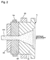
- Fig. 2 is a cross-sectional view of the extrusion die (mold) and the vicinity thereof of the extruder shown in Fig. 1.
- the left side and right side of the extruder in Figs. 1 and 2 are called a "front end" and a "base end", respectively.
- the extruder 1 shown in the figures is a screw extruder which comprises a mounting (not shown), a cylinder 2 supported by the mounting, adapter plates 61 and 62, a breaker ring 4, an extrusion die (mold) 5, a screw 3 which rotates in the cylinder 2, a driving mechanism (not shown) which rotationally drives the screw 3, and a hopper 7 which stores the feed stock and supplies the feed stock into the cylinder 2.
- the breaker ring 4 and the extrusion die 5 are disposed between the adapter plates 61 and 62 and are connected to the front end of the cylinder 2 by the adapter plates 61 and 62. In this case, the breaker ring 4 is located between the cylinder 2 and the extrusion die 5.
- the adapter plates 61 and 62 are connected by screws (not shown).
- heaters (heating units) 21 are provided at the periphery of the cylinder 2.
- the extrusion die 5 is composed of an injection side die 51 having a tapered inner diameter gradually decreasing toward the extrusion opening side and an extrusion side die 52 defining the shape of the extruded body. Hollow portions of the injection side die 51 and the extrusion side die 52 are connected.
- a heater 53 (heating unit) is provided at the periphery of the injection side die 51.
- a heater 54 (heating unit) is provided at the periphery of the extrusion side die 52 and a cooling unit 55 is provided at the front end (side wall at an extrusion opening side).
- the feed stock (not shown) supplied to the hopper 7 is fed into the cylinder 2.
- the screw 3 is rotationally driven in a predetermined direction at a predetermined rotational speed by the driving mechanism.
- the rotational speed of the screw 2 is not specifically limited; however, it is preferably, for example, 1 to 250 rpm.
- the cylinder 2 and the injection side die 51 are heated by the heaters 21 and 53, respectively, so as to have a predetermined temperature profile.
- the feed stock is heated at or above the melting temperature (melting point) of the binder (thermoplastic) in the feed stock and is melted while being transported in the cylinder 2 toward the front end side.
- the viscosity of the melted material of the feed stock becomes low, so that the fluidity thereof is improved, and air pores in the melted material are removed by compaction thereof.
- the temperature of the cylinder 2 and that of the injection side die 51 are not specifically limited and are appropriately determined in accordance with the binder, the organic material, and the like, to be used. However, they are each preferably within approximately 100 to 400°C, and more preferably, approximately 120 to 350°C.
- the melted material of the feed stock is fed from a front edge of the cylinder 2 into the breaker ring 4, is transported in the breaker ring 4 toward the extrusion die 5 side, and is then injected from a front edge of the breaker ring 4 into the extrusion die 5.
- the melted material of the feed stock fed into the extrusion die 5 is continuously extruded from the extrusion die 5, so that the melted material is formed into a predetermined shape.
- the temperatures at the extrusion side die 52 are controlled to have a predetermined temperature gradient by the cooling unit 55 and the heater 54 so as to cool and solidify the melted material of the feed stock.
- the temperatures of the extrusion side die 52 are higher than the predetermined temperature, the extrusion side die 52 is cooled by the cooling unit 55, and in contrast, when the temperatures of the extrusion side die 52 are lower than the predetermined temperature, the extrusion side die 52 is heated by the heater 54.
- the extruded body 100 is cut into a predetermined length, and extruded products having desired shapes and dimensions are obtained.
- the temperature of the extrusion side die 52 (temperature of the extrusion die 5 in the vicinity of the extrusion opening) is preferably set to be lower than the temperature of the injection side die 51 (temperature of the extrusion die 5 in the vicinity of the injection opening), and specifically, is preferably set to be lower than the melting point of the binder and to be higher than the melting point of the organic material.
- the extrusion molding in which the temperature of the extrusion side die 52 is lower than the melting point of the binder and is higher than the melting point of the organic material, is performed, the organic material in the feed stock is in the melted state and only the binder is solidified. Consequently, the extruded body 100 is extruded from the extrusion die 5 while maintaining the shape thereof. That is, smooth and secure extrusion molding can be performed.
- the extruded body 100 formed by extrusion molding can maintain its shape, so that further improved dimensional accuracy thereof can be achieved.
- the temperature of the extrusion side die 52 is not specifically limited, and is appropriately determined by the binder, the organic material, and the like to be used; however, it is preferably approximately 30 to 120°C, and more preferably, approximately 30 to 90°C.
- the extrusion pressure is preferably not more than 1,000 kg/cm 2 , and more preferably, not more than 500 kg/cm 2 .
- the extrusion speed is preferably approximately 0.1 to 50 mm/sec, and more preferably, approximately 0.2 to 20 mm/sec.
- the transverse cross-sectional shape of the extruded body 100 is determined by the shape of the extrusion opening of the extrusion die 5 to be selected.
- an extruded body (metal product as a finished product) in the form of a circular bar or in the form of a plate is obtained, and when the extrusion die is composed of an outer die and an inner die, an extruded body (metal product as a finished product) in the form of a hollow shape such as a circular cylinder is obtained.
- a thin-walled extruded body or extruded body having an irregular cross-sectional shape can be easily manufactured in accordance with a shape of the extrusion opening of the extrusion die 5 to be selected.
- the extruded products (metal products as a finished product) having various lengths, such as a flat and a continuous form, can be manufactured.
- the screw extruder was representatively described; however, the present invention is not limited thereto.
- Extrusion molding may be performed using other machines such as a ram extruder.
- the ram extruder has a structure provided with a piston, which moves back and forth in the cylinder 2 in place of the screw 3, in the extruder 1 shown in Fig. 1.
- a mixture of the constituents, in place of the feed stock, may be stored in the hopper 7 and may be fed into the cylinder 2.
- a debinding treatment (treatment for removing the binder) of the extruded body obtained in the process [2A] described above is performed.
- a heat treatment in a non-oxidizing atmosphere such as in a vacuum or under a reduced pressure (for example, 1 ⁇ 10 -1 to 1 ⁇ 10 -6 Torr), or in an inert gas atmosphere, such as nitrogen gas and argon gas, is performed.
- the heating condition is preferably at approximately 150 to 750°C for approximately 0.5 to 40 hours, and more preferably, at approximately 250 to 650°C for approximately 1 to 24 hours.
- Debinding by the heat treatment thus described may be performed in multiple steps depending on individual purposes (for example, for shortening the debinding time).
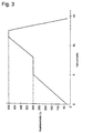
- debinding is preferably performed in a first step for debinding in a low temperature region and a second step for debinding in a temperature region higher than that of the first step (refer Fig. 3).
- debinding in a low temperature region be performed first and then debinding in a high temperature region (the second step) be performed.
- the decomposition temperature of a resin and the like relates to the melting point thereof, and the decomposition temperature of the organic material in the extruded body is lower than that of the binder.
- the organic material having the lower decomposition temperature is decomposed and removed in the first step, and then the binder having the higher decomposition temperature is decomposed and removed in the second step.
- the binder is removed through voids (air pores) formed by the decomposition and removal of the organic material.
- debinding can be efficiently performed, and the debinding time can be shortened.
- generation of debinding defects, such as breakage can be securely prevented, and debinding from the extruded body is uniformly performed, so that deformation of the extruded body is prevented, and the dimensional accuracy thereof is improved.
- the heat treatment condition in the first step is preferably approximately 100 to 400°C for approximately 0.5 to 30 hours, and more preferably, approximately 150 to 350°C for approximately 1 to 20 hours.
- the heat treatment condition in the second step is preferably approximately 250 to 750°C for approximately 0.5 to 35 hours, and more preferably, approximately 150 to 350°C for approximately 1 to 24 hours.
- the debinding treatment may be performed by extracting specific components out of the binder, the organic material and the additive, using a predetermined solvent (liquid or gas).
- the debound body (extruded body subjected to debinding treatment) obtained in the process [3A] is baked so as to be sintered in a sintering furnace, whereby the metal sintered body (sintered body) is manufactured.
- the metal powder diffuses and the grains thereof grow so as to form crystal grains, whereby a dense body, i.e., a sintered body having a high density and low porosity, as a whole, is obtained.
- the sintering temperature in sintering is not specifically limited; however, when the metal is iron or a ferrous alloy, approximately 950 to 1,450°C is preferable, and approximately 1,100 to 1,400°C is more preferable, and when the metal is titanium or a titanium alloy, approximately 900 to 1,350°C is preferable, and approximately 1,000 to 1,300°C is more preferable.
- the sintering time in the case in which the sintering temperature is as described above, is preferably approximately 0.5 to 8 hours, and more preferably, approximately 1 to 5 hours.
- the sintering atmosphere is preferably a non-oxidizing atmosphere. According to this, reduction of the porosity of the sintered body is achieved.
- the sintering atmosphere is preferably a vacuum of not more than 1 ⁇ 10 -2 Torr (more preferably 1 ⁇ 10 -2 to 1 ⁇ 10 -6 Torr), an inert gas atmosphere, such as nitrogen gas and argon gas, of 1 to 760 Torr, or a hydrogen gas atmosphere of 1 to 760 Torr.
- the sintering atmosphere may be changed while sintering is performed.
- the sintering atmosphere is a vacuum of 1 ⁇ 10 -2 to 1 ⁇ 10 -6 Torr, and is then changed to the inert gas atmosphere described above while sintering is being performed.
- Sintering may be performed in two steps or more. For example, a first and a second sintering step, which have different conditions from each other, may be performed. In this case, the temperature of the second sintering step may be higher than that of the first sintering step.
- a process prior to the process [1A], an intermediate process between the processes [1A] to [4A], and a process after the process [4A] may exist.
- the sintered body metal product
- a sintered body in a continuous form and the product cut therefrom which has higher dimensional accuracy, can be continuously manufactured and is suitable for mass production.
- products composed of high speed steel, die steel, hard materials, and the like, specifically the products thereof in a continuous form or the product cut therefrom, which are difficult to be processed by conventional hot extrusion, can be easily manufactured. That is, there is a large degree of freedom for selecting usable metals.
- extrusion molding may be performed when the temperature of the extrusion side die 52 of the extrusion die 5 is lower than the melting point of the binder and is higher than the melting point of the organic material, and debinding may be separately performed in a first step and a second step.
- the temperature of the extrusion side die 52 of the extrusion die 5 is controlled using the cooling unit 55 and the heater 54, and hence, the temperature thereof can be securely set to be a target temperature.
- Metal powder, binders, and organic materials, described below, were mixed, and then kneaded at 135°C for 1 hour by using a kneading machine, whereby the kneaded product was obtained.
- the obtained kneaded product was pulverized and then sieved so as to obtain pellets having an average diameter of 3 mm.
- the pellets were extrusion molded under the conditions described below using the extrusion machine shown in Fig. 1, and a extruded body was cut into circular cylindrical extruded products (outer diameter of ⁇ 22.5 mm, inner diameter of ⁇ 18.0 mm, and length of 56 mm).
- extrusion die of the extrusion machine an extrusion die for forming an extruded product in the form of a circular cylinder was used.
- the temperature was held at 300°C for 3 hours, and in a second step, the temperature was held at 500°C for 1 hour.
- the obtained debound products (the extruded products subjected to the debinding treatment) were sintered at 1,350°C for 3 hours in an argon atmosphere, so that the sintered products in the form of a circular cylinder (target dimensions: a metal product having an outer diameter of ⁇ 20.0 mm, an inner diameter of ⁇ 16.0 mm, and a length of 50 mm) were obtained.
- Sintered bodies (target dimensions: a metal product having an outer diameter ⁇ of 20.0 mm, an inner diameter ⁇ of 16.0 mm, and a length of 50 mm) were obtained in a similar manner to those performed in Example 1 except for replacing the raw materials with ones listed below.
- Circular cylindrical metal products (target dimensions: an outer diameter of ⁇ 20.0 mm, an inner diameter of ⁇ 16.0 mm) were manufactured from stainless steel (SUS 316L) by hot extrusion.
- the conditions of the hot extrusion were a temperature of 1,100°C and an extrusion pressure of 3 tons/cm 2 .
- the sintered bodies of the present invention since extrusion molding in which the extrusion die is provided with a temperature gradient along the extrusion direction is performed, a sintered metal product (sintered product) having high dimensional accuracy, specifically a product in a continuous form or products cut therefrom, can be easily obtained.
- the composition includes metal powder, a binder, and an organic material having a melting point lower than that of the binder
- the moldability during extrusion molding and the debinding characteristics during debinding can be improved.
- the dimensional accuracy of the sintered metal product can be improved, and the time required for manufacturing the sintered metal product can be shortened.
- the debinding step comprises a first debinding step in a lower temperature region and a second debinding step in a temperature region higher than that of the first debinding step
- debinding can be efficiently performed, the time required for debinding can be shortened, and generation of debinding defects, such as a breakage, can be securely prevented.
- the dimensional accuracy of the sintered metal product can be improved.
Landscapes
- Engineering & Computer Science (AREA)
- Manufacturing & Machinery (AREA)
- Mechanical Engineering (AREA)
- Powder Metallurgy (AREA)
Abstract
Description
wherein, in the extrusion molding step, the extrusion die is provided with a temperature gradient along the extrusion direction.
- Fig. 1
- is a cross-sectional view of an example of a configuration of an extruder used for the present invention.
- Fig. 2
- is a cross-sectional view of an extrusion die (mold) and the vicinity thereof of the extruder shown in Fig. 1.
- Fig. 3
- is a graph showing an example of changes in a furnace temperature vs. time in a debinding step of the present invention.
- 1:
- extruder
- 2:
- cylinder
- 21:
- heater
- 3:
- screw
- 4:
- breaker ring
- 5:
- extrusion die (mold)
- 51:
- injection side die(inlet)
- 52:
- extrusion side die(outlet)
- 53, 54:
- heater (heating unit)
- 55:
- cooling unit
- 61, 62:
- adapter plate
- 7:
- hopper
- 100:
- extruded body
- Example 1:
- Error ± 0.15%
- Example 2:
- Error ± 0.40%
- Comparative Example 1:
- Error ± 3.0%
Claims (8)
- A method of manufacturing a sintered body comprising:an extrusion molding step of extruding a feed stock comprising metal powder and a binder from an extrusion die of an extruder so as to form an extruded body;a debinding step of debinding the extruded body; anda sintering step of sintering the debound extruded body so as to manufacture the sintered body;
wherein, in the extrusion molding step, the extrusion die is provided with a temperature gradient along the extrusion direction. - The method of manufacturing a sintered body according to Claim 1, wherein a temperature gradient is provided so that a temperature of the extrusion die at an extrusion opening side is lower.
- The method of manufacturing a sintered body according to one of Claims 1 and 2, wherein the feed stock further comprises an organic material having a melting point which is lower than that of the binder.
- The method of manufacturing a sintered body according to Claim 3, wherein the organic material functions as a binder.
- The method of manufacturing a sintered body according to Claim 3, wherein the melting point of the binder is 80 to 300°C and the melting point of the organic material is -50 to 80°C.
- The method of manufacturing a sintered body according to Claim 3, wherein the extrusion molding step is performed at a temperature of the extrusion die of less than the melting point of the binder and more than the melting point of the organic material in the vicinity of an extrusion opening.
- The method of manufacturing a sintered body according to one of Claims 1 and 2, wherein the extrusion molding step is performed with the temperature of the extrusion die in the vicinity of an extrusion opening being controlled using a cooling unit and a heating unit.
- The method of manufacturing a sintered body according to one of Claims 1 and 2, wherein the debinding step further comprises a first step of debinding performed in a low temperature region and a second step of debinding performed in a temperature region higher than that in the first step.
Applications Claiming Priority (3)
| Application Number | Priority Date | Filing Date | Title |
|---|---|---|---|
| JP29121098 | 1998-10-13 | ||
| JP29121098A JP4019522B2 (en) | 1998-10-13 | 1998-10-13 | Method for manufacturing sintered body |
| PCT/JP1999/005599 WO2000021703A1 (en) | 1998-10-13 | 1999-10-08 | Method of producing sintered body |
Publications (3)
| Publication Number | Publication Date |
|---|---|
| EP1040887A1 true EP1040887A1 (en) | 2000-10-04 |
| EP1040887A4 EP1040887A4 (en) | 2001-12-19 |
| EP1040887B1 EP1040887B1 (en) | 2005-09-28 |
Family
ID=17765898
Family Applications (1)
| Application Number | Title | Priority Date | Filing Date |
|---|---|---|---|
| EP99970345A Expired - Lifetime EP1040887B1 (en) | 1998-10-13 | 1999-10-08 | Method of producing sintered body |
Country Status (6)
| Country | Link |
|---|---|
| US (1) | US6555051B1 (en) |
| EP (1) | EP1040887B1 (en) |
| JP (1) | JP4019522B2 (en) |
| KR (1) | KR100404527B1 (en) |
| DE (1) | DE69927475T2 (en) |
| WO (1) | WO2000021703A1 (en) |
Cited By (4)
| Publication number | Priority date | Publication date | Assignee | Title |
|---|---|---|---|---|
| NO326944B1 (en) * | 2006-11-20 | 2009-03-16 | Norsk Hydro As | Extruder for continuous extrusion of high viscosity materials |
| CN109500384A (en) * | 2018-12-07 | 2019-03-22 | 东莞市华研新材料科技有限公司 | Processing and manufacturing process of shell for mobile phone frame based on metal powder injection molding |
| CN110408897A (en) * | 2019-08-13 | 2019-11-05 | 北京航大微纳科技有限公司 | A kind of vertical binding device and binding method of rotary target material |
| CN111468548A (en) * | 2020-04-22 | 2020-07-31 | 永城职业学院 | Forming device and forming method for building metal material |
Families Citing this family (14)
| Publication number | Priority date | Publication date | Assignee | Title |
|---|---|---|---|---|
| US7691174B2 (en) * | 2004-03-08 | 2010-04-06 | Battelle Memorial Institute | Feedstock composition and method of using same for powder metallurgy forming a reactive metals |
| US20060024190A1 (en) * | 2004-07-27 | 2006-02-02 | General Electric Company | Preparation of filler-metal weld rod by injection molding of powder |
| US7387763B2 (en) * | 2004-07-27 | 2008-06-17 | General Electric Company | Preparation of sheet by injection molding of powder, consolidation, and heat treating |
| ES2738003T3 (en) * | 2004-10-15 | 2020-01-17 | Taisei Kogyo Co Ltd | Production process of porous sinter, porous sinter and porous sinter molding material |
| JP4702308B2 (en) * | 2007-02-28 | 2011-06-15 | セイコーエプソン株式会社 | Method for manufacturing sintered body |
| US7883662B2 (en) * | 2007-11-15 | 2011-02-08 | Viper Technologies | Metal injection molding methods and feedstocks |
| US8124187B2 (en) | 2009-09-08 | 2012-02-28 | Viper Technologies | Methods of forming porous coatings on substrates |
| DE102010050689A1 (en) | 2010-11-06 | 2012-05-10 | Schaeffler Technologies Gmbh & Co. Kg | Process for producing a ceramic rolling element |
| JP6246500B2 (en) * | 2013-05-28 | 2017-12-13 | 日本電産サンキョー株式会社 | Rare earth magnet manufacturing method |
| JP6390108B2 (en) * | 2014-02-07 | 2018-09-19 | セイコーエプソン株式会社 | Sintered modeling material, sintered modeling method, sintered model and sintered modeling apparatus |
| CN104325144B (en) * | 2014-10-27 | 2017-01-25 | 福立旺精密机电(中国)股份有限公司 | Metal injecting molding catalytic debinding method and catalytic debinding furnace |
| KR101776616B1 (en) * | 2015-10-02 | 2017-09-11 | 주식회사 쓰리디컨트롤즈 | Three dimensional printing apparatus and method using method metal powder-containing material |
| CN110919008A (en) * | 2019-11-22 | 2020-03-27 | 东莞市豪准金属制品有限公司 | Metal injection molding process |
| WO2021110827A1 (en) * | 2019-12-04 | 2021-06-10 | Grundfos Holding A/S | A method of manufacturing a composite component with varying electric resistivity along a longitudinal direction |
Family Cites Families (10)
| Publication number | Priority date | Publication date | Assignee | Title |
|---|---|---|---|---|
| US2787022A (en) | 1955-04-05 | 1957-04-02 | Dow Chemical Co | Extrusion apparatus |
| US3155502A (en) * | 1960-08-12 | 1964-11-03 | Union Carbide Corp | Powder metallurgy |
| US4457851A (en) * | 1981-12-29 | 1984-07-03 | Hitachi Metals, Ltd. | Ferrite magnet and method of producing same |
| JPH07111924B2 (en) * | 1984-04-12 | 1995-11-29 | セイコーエプソン株式会社 | Magnetic roll and method for manufacturing cylindrical magnet for magnetic roll |
| JPS60221501A (en) * | 1984-04-17 | 1985-11-06 | Honda Motor Co Ltd | Production of sintered metallic body |
| JPH0686608B2 (en) * | 1987-12-14 | 1994-11-02 | 川崎製鉄株式会社 | Method for producing iron sintered body by metal powder injection molding |
| CA2014974A1 (en) * | 1989-03-18 | 1991-10-19 | Ken Ikuma | Dies for extrusion moulding |
| EP0452580B1 (en) * | 1990-04-19 | 1999-06-23 | Seiko Epson Corporation | A resin bound magnet and its production process |
| WO1994020242A1 (en) * | 1993-03-09 | 1994-09-15 | Citizen Watch Co., Ltd. | Process for manufacturing powder injection molded parts |
| JP2768356B2 (en) * | 1996-08-27 | 1998-06-25 | セイコーエプソン株式会社 | Method for manufacturing resin-bonded magnet |
-
1998
- 1998-10-13 JP JP29121098A patent/JP4019522B2/en not_active Expired - Fee Related
-
1999
- 1999-10-08 US US09/581,672 patent/US6555051B1/en not_active Expired - Fee Related
- 1999-10-08 EP EP99970345A patent/EP1040887B1/en not_active Expired - Lifetime
- 1999-10-08 KR KR10-2000-7006411A patent/KR100404527B1/en not_active Expired - Fee Related
- 1999-10-08 WO PCT/JP1999/005599 patent/WO2000021703A1/en not_active Ceased
- 1999-10-08 DE DE69927475T patent/DE69927475T2/en not_active Expired - Lifetime
Cited By (5)
| Publication number | Priority date | Publication date | Assignee | Title |
|---|---|---|---|---|
| NO326944B1 (en) * | 2006-11-20 | 2009-03-16 | Norsk Hydro As | Extruder for continuous extrusion of high viscosity materials |
| CN109500384A (en) * | 2018-12-07 | 2019-03-22 | 东莞市华研新材料科技有限公司 | Processing and manufacturing process of shell for mobile phone frame based on metal powder injection molding |
| CN110408897A (en) * | 2019-08-13 | 2019-11-05 | 北京航大微纳科技有限公司 | A kind of vertical binding device and binding method of rotary target material |
| CN110408897B (en) * | 2019-08-13 | 2023-05-05 | 北京航大微纳科技有限公司 | Vertical binding device and binding method for rotary target |
| CN111468548A (en) * | 2020-04-22 | 2020-07-31 | 永城职业学院 | Forming device and forming method for building metal material |
Also Published As
| Publication number | Publication date |
|---|---|
| EP1040887A4 (en) | 2001-12-19 |
| EP1040887B1 (en) | 2005-09-28 |
| KR100404527B1 (en) | 2003-11-05 |
| DE69927475T2 (en) | 2006-06-22 |
| US6555051B1 (en) | 2003-04-29 |
| JP2000119703A (en) | 2000-04-25 |
| WO2000021703A1 (en) | 2000-04-20 |
| KR20010033052A (en) | 2001-04-25 |
| JP4019522B2 (en) | 2007-12-12 |
| DE69927475D1 (en) | 2006-02-09 |
Similar Documents
| Publication | Publication Date | Title |
|---|---|---|
| US6555051B1 (en) | Method for producing sintered body | |
| US7232473B2 (en) | Composite material containing tungsten and bronze | |
| JP2003504518A (en) | Method of forming microporous metal member | |
| KR100641404B1 (en) | Method for Manufacturing Self-Brazing Molded Products Using Powder Metallurgy | |
| KR20010074911A (en) | Powder metal injection molding process for forming an article from the Nickle-based superalloy "HASTELLOY X" | |
| US6761852B2 (en) | Forming complex-shaped aluminum components | |
| WO2006130153A2 (en) | Method and composition for making a wire | |
| CA2347639A1 (en) | Rapid manufacture of metal and ceramic tooling by injection molding | |
| WO2020200426A1 (en) | Sinterable feedstock for use in 3d printing devices | |
| EP1719566B1 (en) | Microwave processing of MIM preforms | |
| CN116890118B (en) | Integrated preparation method for aluminum electrolysis metal anode shell and electric connection | |
| JP2009299106A (en) | Method for producing composite sintered compact, and composite sintered compact | |
| EP1077099B1 (en) | Method of producing metal sintered compacts | |
| US20080075619A1 (en) | Method for making molybdenum parts using metal injection molding | |
| EP1381484A2 (en) | Production of component parts by metal injection moulding (mim) | |
| EP1510273B1 (en) | Method of manufacturing hard material components | |
| WO2001028717A1 (en) | Method of producing watchband parts | |
| JP6673682B2 (en) | Manufacturing method of sintered body | |
| US6315935B1 (en) | Low pressure injection molding of knife blades from metal feedstocks | |
| JPH11315304A (en) | Manufacture of sintered body | |
| JPH11315305A (en) | Manufacture of sintered body | |
| JPH0244882B2 (en) | ||
| JPH03232904A (en) | Alloy powder extrusion molded body and its sintered product | |
| JPH11181501A (en) | Method for producing metal powder and sintered body | |
| JPH0826364B2 (en) | Extrusion molding method of rapidly solidified metal powder |
Legal Events
| Date | Code | Title | Description |
|---|---|---|---|
| PUAI | Public reference made under article 153(3) epc to a published international application that has entered the european phase |
Free format text: ORIGINAL CODE: 0009012 |
|
| 17P | Request for examination filed |
Effective date: 20000712 |
|
| AK | Designated contracting states |
Kind code of ref document: A1 Designated state(s): AT BE CH CY DE DK ES FI FR GB GR IE IT LI LU MC NL PT SE |
|
| A4 | Supplementary search report drawn up and despatched |
Effective date: 20011107 |
|
| AK | Designated contracting states |
Kind code of ref document: A4 Designated state(s): AT BE CH CY DE DK ES FI FR GB GR IE IT LI LU MC NL PT SE |
|
| RIC1 | Information provided on ipc code assigned before grant |
Free format text: 7B 22F 3/20 A, 7B 22F 3/22 B |
|
| 17Q | First examination report despatched |
Effective date: 20030224 |
|
| RAP1 | Party data changed (applicant data changed or rights of an application transferred) |
Owner name: SEIKO EPSON CORPORATION |
|
| RBV | Designated contracting states (corrected) |
Designated state(s): DE FR GB |
|
| GRAP | Despatch of communication of intention to grant a patent |
Free format text: ORIGINAL CODE: EPIDOSNIGR1 |
|
| GRAS | Grant fee paid |
Free format text: ORIGINAL CODE: EPIDOSNIGR3 |
|
| GRAA | (expected) grant |
Free format text: ORIGINAL CODE: 0009210 |
|
| AK | Designated contracting states |
Kind code of ref document: B1 Designated state(s): DE FR GB |
|
| REG | Reference to a national code |
Ref country code: GB Ref legal event code: FG4D |
|
| REF | Corresponds to: |
Ref document number: 69927475 Country of ref document: DE Date of ref document: 20060209 Kind code of ref document: P |
|
| ET | Fr: translation filed | ||
| PLBE | No opposition filed within time limit |
Free format text: ORIGINAL CODE: 0009261 |
|
| STAA | Information on the status of an ep patent application or granted ep patent |
Free format text: STATUS: NO OPPOSITION FILED WITHIN TIME LIMIT |
|
| 26N | No opposition filed |
Effective date: 20060629 |
|
| PGFP | Annual fee paid to national office [announced via postgrant information from national office to epo] |
Ref country code: DE Payment date: 20091001 Year of fee payment: 11 |
|
| PGFP | Annual fee paid to national office [announced via postgrant information from national office to epo] |
Ref country code: GB Payment date: 20091007 Year of fee payment: 11 Ref country code: FR Payment date: 20091029 Year of fee payment: 11 |
|
| GBPC | Gb: european patent ceased through non-payment of renewal fee |
Effective date: 20101008 |
|
| PG25 | Lapsed in a contracting state [announced via postgrant information from national office to epo] |
Ref country code: FR Free format text: LAPSE BECAUSE OF NON-PAYMENT OF DUE FEES Effective date: 20101102 |
|
| REG | Reference to a national code |
Ref country code: FR Ref legal event code: ST Effective date: 20110630 |
|
| REG | Reference to a national code |
Ref country code: DE Ref legal event code: R119 Ref document number: 69927475 Country of ref document: DE Effective date: 20110502 |
|
| PG25 | Lapsed in a contracting state [announced via postgrant information from national office to epo] |
Ref country code: GB Free format text: LAPSE BECAUSE OF NON-PAYMENT OF DUE FEES Effective date: 20101008 |
|
| PG25 | Lapsed in a contracting state [announced via postgrant information from national office to epo] |
Ref country code: DE Free format text: LAPSE BECAUSE OF NON-PAYMENT OF DUE FEES Effective date: 20110502 |