EP1040313B1 - Einrichtung zur induktion eines magnetfelds im mündungsbereich einer abschusseinrichtung - Google Patents
Einrichtung zur induktion eines magnetfelds im mündungsbereich einer abschusseinrichtung Download PDFInfo
- Publication number
- EP1040313B1 EP1040313B1 EP98964475A EP98964475A EP1040313B1 EP 1040313 B1 EP1040313 B1 EP 1040313B1 EP 98964475 A EP98964475 A EP 98964475A EP 98964475 A EP98964475 A EP 98964475A EP 1040313 B1 EP1040313 B1 EP 1040313B1
- Authority
- EP
- European Patent Office
- Prior art keywords
- permanent magnets
- inductions
- different
- missile
- igniter
- Prior art date
- Legal status (The legal status is an assumption and is not a legal conclusion. Google has not performed a legal analysis and makes no representation as to the accuracy of the status listed.)
- Expired - Lifetime
Links
- 230000005291 magnetic effect Effects 0.000 title claims abstract description 49
- 230000001939 inductive effect Effects 0.000 title description 2
- 230000006698 induction Effects 0.000 claims abstract description 44
- 238000010304 firing Methods 0.000 claims description 13
- 238000000034 method Methods 0.000 claims description 9
- 230000001960 triggered effect Effects 0.000 claims description 4
- 230000002123 temporal effect Effects 0.000 claims 5
- 230000000694 effects Effects 0.000 abstract description 2
- 239000007789 gas Substances 0.000 abstract description 2
- 230000035939 shock Effects 0.000 abstract description 2
- BGPVFRJUHWVFKM-UHFFFAOYSA-N N1=C2C=CC=CC2=[N+]([O-])C1(CC1)CCC21N=C1C=CC=CC1=[N+]2[O-] Chemical compound N1=C2C=CC=CC2=[N+]([O-])C1(CC1)CCC21N=C1C=CC=CC1=[N+]2[O-] BGPVFRJUHWVFKM-UHFFFAOYSA-N 0.000 description 4
- 239000000463 material Substances 0.000 description 4
- 230000005294 ferromagnetic effect Effects 0.000 description 2
- 239000004033 plastic Substances 0.000 description 2
- 229920003023 plastic Polymers 0.000 description 2
- 235000015842 Hesperis Nutrition 0.000 description 1
- 235000012633 Iberis amara Nutrition 0.000 description 1
- 108010076504 Protein Sorting Signals Proteins 0.000 description 1
- 230000009471 action Effects 0.000 description 1
- 230000002411 adverse Effects 0.000 description 1
- 230000008901 benefit Effects 0.000 description 1
- 230000005540 biological transmission Effects 0.000 description 1
- 238000005422 blasting Methods 0.000 description 1
- 239000003795 chemical substances by application Substances 0.000 description 1
- 239000004020 conductor Substances 0.000 description 1
- 230000007797 corrosion Effects 0.000 description 1
- 238000005260 corrosion Methods 0.000 description 1
- 238000010616 electrical installation Methods 0.000 description 1
- 230000004907 flux Effects 0.000 description 1
- 230000006870 function Effects 0.000 description 1
- 229920006015 heat resistant resin Polymers 0.000 description 1
- 229910052751 metal Inorganic materials 0.000 description 1
- 239000002184 metal Substances 0.000 description 1
- 150000002739 metals Chemical class 0.000 description 1
- 230000005298 paramagnetic effect Effects 0.000 description 1
- 230000008569 process Effects 0.000 description 1
Images


Classifications
-
- F—MECHANICAL ENGINEERING; LIGHTING; HEATING; WEAPONS; BLASTING
- F42—AMMUNITION; BLASTING
- F42C—AMMUNITION FUZES; ARMING OR SAFETY MEANS THEREFOR
- F42C17/00—Fuze-setting apparatus
- F42C17/04—Fuze-setting apparatus for electric fuzes
-
- F—MECHANICAL ENGINEERING; LIGHTING; HEATING; WEAPONS; BLASTING
- F41—WEAPONS
- F41A—FUNCTIONAL FEATURES OR DETAILS COMMON TO BOTH SMALLARMS AND ORDNANCE, e.g. CANNONS; MOUNTINGS FOR SMALLARMS OR ORDNANCE
- F41A21/00—Barrels; Gun tubes; Muzzle attachments; Barrel mounting means
- F41A21/32—Muzzle attachments or glands
-
- F—MECHANICAL ENGINEERING; LIGHTING; HEATING; WEAPONS; BLASTING
- F41—WEAPONS
- F41A—FUNCTIONAL FEATURES OR DETAILS COMMON TO BOTH SMALLARMS AND ORDNANCE, e.g. CANNONS; MOUNTINGS FOR SMALLARMS OR ORDNANCE
- F41A35/00—Accessories or details not otherwise provided for
-
- F—MECHANICAL ENGINEERING; LIGHTING; HEATING; WEAPONS; BLASTING
- F42—AMMUNITION; BLASTING
- F42C—AMMUNITION FUZES; ARMING OR SAFETY MEANS THEREFOR
- F42C11/00—Electric fuzes
- F42C11/04—Electric fuzes with current induction
Definitions
- the invention relates to a launcher with means for generating a magnetic field in the area the mouth of the launcher according to the preamble of the first Claim and a method for transmitting a signal to a Electronics of a detonator and, if necessary, a Steurnikes a missile in the region of the mouth of a launching device according to claim 2.
- induction can in an induction device, for example in a Coil system, of missiles, which can in particular projectiles but also For example, rockets be fired at launch electrical energy.
- This serves for the power supply of electrically triggered detonators, but can also be used for the supply of control circuits are used, so during the flight phase or, upon reaching the destination, certain operations such as arming or unlocking Ejecting operations, executable.
- From DE-OS 27 06 168 is a device for generating an electrical Ignition current in the fuse of a projectile known.
- the projectile contains one Permanent magnet ring and a part of a yoke.
- the other part of the yoke is located at the end of the barrel and consists of a number ferromagnetic rings, between which paramagnetic rings are arranged.
- EP-A-0 359 908 (basis for claims 1 and 2) and EP-A-0 783 095 it is known that in two successively arranged magnets in the launcher from the through the first magnet triggered induction a start-stop counter is turned on while counting is stopped by the induction of the second magnet. This is not an independent signal conveying an information.
- the counting process is used only to determine the time that the projectile is on the way between the used two magnets. Due to the known distance of the two Magnets can be calculated by means of time the projectile velocity.
- Object of the present invention is to provide a simple and secure device for Generation of a voltage in an induction device of a missile at To provide firing.
- the object is achieved by means of the characterizing features of the first Claim and the characterizing features of the second claim.
- the arrangement of the permanent magnets around the launcher can be annular. As a result, a uniform structure of the magnetic field and achieved a uniform induction effect in the launcher.
- the permanent magnets embedded in a non-magnetizable material can For example, heat-resistant resins or plastics and non-magnetizable Be metals. It can, as already stated, a complete enclosure of the Permanent magnets be provided so that they against any action the launcher are protected.
- the magnetic field strength generated by the permanent magnets must on the need for electrical energy of the igniter or a Control circuit of the missile, a projectile or a rocket, tuned be. It is therefore advantageous that a plurality of permanent magnets, in Weft direction seen, are arranged one behind the other. Through multiple inductions in a coil, the voltage induced in the inductor can be increased become.
- the induction sequence as a Code can be used, for example, a setting of the ignition timing or flight duration or heading, if appropriate Electronics is present in the projectile or the rocket.
- the sequence of inductions in different Time intervals are used.
- Such a signal sequence can then be achieved advantageously be when the magnets are arranged at predetermined distances from each other, these distances can be different.
- the arrangement of the permanent magnets at predetermined intervals is then advantageous if the magnets are arranged so that the magnetic fields themselves if possible, do not negatively influence each other.
- the distances in coordination the magnetic fields are selected.
- signals to the detonator of a projectile or the To transmit control circuit of a rocket is that permanent magnets with different magnetic field strengths at different distances be arranged to each other. This makes it possible by the time different sequence of inductions in combination with their different Intensities to produce a sequence of signals.
- the prerequisite is that the Ignition system includes an electronic circuit, both from the different intensity as well as from the different sequence of Inductions each forms the desired signal. This is an even greater number Coding possible, for example, a particular setting of Ignition timing or by control circuits.
- the time intervals and the different height of the Induction voltages can be three according to the specified specifications different information to the electronics of a detonator or a Transfer control circuit, such as a steering system, a missile, if this is set up accordingly.
- a weapon barrel 1 is shown by a launcher according to the prior art.
- the Device 3 comprises a housing 4 containing the permanent magnet 5.
- the permanent magnet 5 is completely from a non-magnetizable material 4, for example a heat-resistant Plastic, which simultaneously forms the housing for the magnet and him so protects against the launching gases.
- a non-magnetizable material 4 for example a heat-resistant Plastic
- the housing 4 is on the mouth 2 of the gun barrel. 1 screwed. From the area of the mouth 2 of the gun barrel 1 is just entering Projectile 7 off.
- the weapon barrel 1, the device 3 for generating the magnetic field 9 and the projectile 7 are shown in section.
- the permanent magnet 5 surrounds in the present example the Launcher 8 annular.
- the magnetic field 9 generated by him has a given magnetic field strength.
- the projectile 7 moves through the Launch channel 8 in the firing direction 10 through the device 3 with the permanent magnet 5.
- the induction device 11 of the moves Igniter Z of the projectile 7, in the present example an annular Coil 11, through the magnetic field 9.
- a voltage is induced by the predetermined Magnetic field 9 and 7 is predetermined by the movement of the projectile.
- the induced voltage is via the conductor 12 of the electronics 13 of the projectile. 7 fed, and there in a suitable form, for example in a condenser 14, stored and held ready for the ignition of Warsprengstoffs 25.
- the induced voltage could be used with the help of one here not shown electronics to predict the ignition timing.
- the Use of the induced voltage is not the subject of the present Invention and known from the cited prior art already sufficiently known.
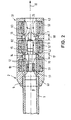
- the embodiment of Figure 2 shows a launcher 1, a Gun barrel, in the region of the mouth 2, the means 31 for generating a magnetic field comprises three permanent magnets 51, 52 and 53. These Permanent magnets 51, 52 and 53 are seen in the firing direction 10, arranged one behind the other.
- the magnetic field strengths of the three magnets can be the same size, but also different sizes.
- the electronics 13 of the projectile 7 contains additionally a counting circuit 15, with which it is possible to determine the number of inductions, ie the number of permanent magnets 91 to 93 passed.
- the Counting circuit 15 can be used, based on the number of inductions of Electronics 13 of the projectile 7 to provide information.
- the Information can be used, for example, the ignition of the Bullet to pretend.
- the housings 41, 42 and 43 are designed so that the distance 17 between the permanent magnet 51 and the permanent magnet 52 and the Distance 18 between the permanent magnet 52 and the permanent magnet 53 each is the same size.
- the embodiment of Figure 3 shows a means 32 for generating a Magnetic field also three permanent magnets concentric around the Launcher 8 are arranged.
- the permanent magnet 511 close, in Seen firing direction 10, two more permanent magnets 522 and 533 at.
- These permanent magnets each have a magnetic field 922 and 933 extending in its magnetic field strength respectively from the magnetic field 911 of the Permanent magnet 511 is different.
- the magnetic field strengths of Magnetic fields 922 and 933 are also different.
- the distance is 19 between the permanent magnet 511 and the permanent magnet 522 is greater than the distance 20 between the permanent magnet 522 and the Permanent magnets 533.
- the electronics 13 of the projectile 7 contains a memory 14 for the electrical Energy and a counting circuit 15 for the number of inductions in the Passage of the projectile 7 through the magnetic fields 911, 922 and 933.
- a memory 14 for the electrical Energy for the electrical Energy and a counting circuit 15 for the number of inductions in the Passage of the projectile 7 through the magnetic fields 911, 922 and 933.
- the electronic circuit 13 contains of the projectile 7 additionally a circuit 21, with the time intervals between individual inductions, ie between the individual Passages of the induction device 11 through the successive Magnetic fields 911, 922 and 933 are located.
- the different intensity of the magnetic field strengths and thus the different levels of induced voltages as well as the time different distances between the inductions can be for the Transmission of information to the electronics 13 of the projectile 7 use.
- Compared to the previous embodiment is due to the different intensity of the magnetic fields and their different distance significantly increased the possibilities of transmitting information. It can thereby different according to the number of possible codings Functions in the igniter Z are controlled.
- the housings 411 and 422 are connected to each other via screw thread 16.
- the Housing 422 and 433 each have in the present embodiment External thread 23 and are due to the small distances between the two Permanent magnets 522 and 533 connected via a sleeve 22 with each other. Due to the screw connections are the permanent magnets with each other and easily exchangeable with other permanent magnets. This makes it possible due to different distances and the combination of permanent magnets with different magnetic field strengths in each case a voltage in one determined height in the induction device 11 of the projectile 7 to induce and to vary the time intervals of the inductions. This is the Possibility to provide different information to the electronics 13 of the projectile 7 to transfer.
Landscapes
- Engineering & Computer Science (AREA)
- General Engineering & Computer Science (AREA)
- Aiming, Guidance, Guns With A Light Source, Armor, Camouflage, And Targets (AREA)
- Toys (AREA)
- Magnetic Resonance Imaging Apparatus (AREA)
- Arc-Extinguishing Devices That Are Switches (AREA)
- Magnetic Treatment Devices (AREA)
- Electromagnets (AREA)
- Geophysics And Detection Of Objects (AREA)
Description
- Figur 1
- die Anordnung eines Permanentmagneten im Bereich der Mündung einer Abschußeinrichtung entsprechend dem Stand der Technik,
- Figur 2
- die Anordnung von drei Permanentmagneten, in Schußrichtung gesehen hintereinander angeordnet, im Bereich der Mündung einer Abschußeinrichtung und
- Figur 3
- die Anordnung von drei Permanentmagneten mit unterschiedlichen Feldstärken, die in unterschiedlichen Abständen hintereinander angeordnet sind.
Claims (8)
- Abschusseinrichtung (1) mit einer Einrichtung (31; 32) zur Erzeugung eines Magnetfeldes (91, 92, 93; 911, 922, 933), gebildet durch mindestens zwei im Bereich der Mündung (2) der Abschusseinrichtung, in Schussrichtung gesehen hintereinander angeordnete Permanentmagnete (51, 52, 53; 511, 522, 533) zur Induktion einer Spannung in einer Induktionseinrichtung (11) eines die Abschusseinrichtung verlassenden, die Magnetfelder (91, 92, 93; 911, 922, 933) durchlaufenden Flugkörpers (7), dadurch gekennzeichnet, dass bei zwei Permanentmagnetedass bei einer Anzahl von Permanentmagnete (51, 52, 53; 511, 522, 533) über zweii bei vorgegebenem Abstand zwischen den Permanentmagneten die Feldstärken gleich oder unterschiedlich sind oderii bei vorgegebenen gleichen oder unterschiedlichen Feldstärken der Abstand zwischen den Permanentmagneten mittels austauschbarer Permanentmagnete beim Zusammenbau der unterschiedlichen Gehäuse der Permanentmagnete variiert werden kann oderso dass sich auf Grund der aufgeführten möglichen Variationen die Anzahl der Induktionen, die zeitliche Abfolge der Induktionen sowie die Höhe der jeweils induzierten Spannung voneinander unterscheiden und dass die Anzahl der Induktionen, ihre zeitliche Abfolge sowie die Höhe der jeweils induzierten Spannung, einzeln oder in Kombination miteinander, jeweils ein Signal bilden, das nutzbar ist zur Übermittlung einer dem Signal zugeordneten Information an die Elektronik (13) des Zünders (Z) und gegebenenfalls des Steuerkreises des Flugkörpers (7).i ihre Abstände (17, 18) voneinander gleich und ihre Feldstärken (91, 92, 93) gleich sind oderii ihre Abstände voneinander gleich und ihre Feldstärken unterschiedlich sind oderiii ihre Abstände (19, 20) voneinander unterschiedlich und ihre Feldstärken (911, 922, 933) gleich sind oderiv ihre Abstände voneinander unterschiedlich und ihre Feldstärken unterschiedlich sind,
- Verfahren zur Übermittlung eines Signals an eine Elektronik eines Zünders (Z) und gegebenenfalls eines Steuerkreises eines Flugkörpers (7) im Bereich der Mündung (2) einer Abschusseinrichtung (1), wobei mit einer Einrichtung (31, 32) zur Erzeugung von Magnetfeldern, die durch mindestens zwei, in Schussrichtung gesehen hintereinander angeordnete Permanentmagnete (51, 52, 53, 511, 522, 533) gebildet wird, in einer Induktionseinrichtung (11) des Flugkörpers (7) induktionen erzeugt werden und die jeweils erfolgten Induktionen aufgrund ihrer zeitlichen Abfolge als Signal genutzt werden, dadurch gekennzeichnet, dass durch die Veränderung folgender Parameter: der Anzahl der Permanentmagnete (51, 52, 53, 511, 522, 533), der Abstand der Permanentmagnete (51, 52, 53, 511, 522, 533) voneinander und der Feldstärke der Permanentmagnete jeweils einzeln oder in einer beliebigen Kombination miteinander, Induktionen in der Induktionseinrichtung des Flugkörpers (7) erzeugt werden und dass die Anzahl der Induktionen, ihre zeitliche Abfolge sowie die Höhe der jeweils induzierten Spannungen, einzeln oder in Kombination miteinander, als Signal genutzt werden, mit dem eine dem Signal zugeordnete Information an die Etektronik (13) des Zünders (Z) und gegebenenfalls den Steuerkreis des Flugkörpers (7) übermittelt wird.
- Verfahren nach Anspruch 2, dadurch gekennzeichnet, dass die Elektronik (13) des Zünders (Z) eine Zählschaltung aufweist, mit der die Anzahl der Induktionen ermittelt wird.
- Verfahren nach Anspruch 2, dadurch gekennzeichnet, dass die Elektronik (13) des Zünders (Z) eine Schaltung aufweist, mit der die zeitlichen Abstände zwischen den einzelnen Induktionen erfasst werden.
- Verfahren nach Anspruch 2, dadurch gekennzeichnet, dass die Elektronik (13) des Zünders (Z) eine Schaltung aufweist, mit der die unterschiedlichen Höhen der in der Induktionseinrichtung induzierten Spannungen erfasst werden.
- Verfahren nach einem der Ansprüche 2 bis 5, dadurch gekennzeichnet, dass durch eine Kombination von zwei oder mehreren der beanspruchten Merkmale der Umfang der übermittelbaren Information an die Elektronik (13) des Zünders (Z) und gegebenenfalls des Steuerkreises des Flugkörpers (7) bestimmt wird.
- Verfahren nach einem der Ansprüche 2 bis 6, dadurch gekennzeichnet, dass die in der Induktionseinrichtung induzierte Spannung zur Versorgung des elektrisch auszulösenden Zünders (Z) sowie gegebenenfalls eines den Flug beeinflussenden Steuerkreises genutzt wird.
- Verfahren nach einem der Ansprüche 2 bis 7, dadurch gekennzeichnet, dass die Permanentmagnete (51, 52, 53, 511, 522, 533) im Bereich der Mündung (2) der Abschusseinrichtung (1) auswechselbar sind.
Applications Claiming Priority (3)
| Application Number | Priority Date | Filing Date | Title |
|---|---|---|---|
| DE19756357 | 1997-12-18 | ||
| DE19756357A DE19756357B4 (de) | 1997-12-18 | 1997-12-18 | Einrichtung zur Induktion eines Magnetfelds im Mündungsbereich einer Abschußeinrichtung |
| PCT/EP1998/007790 WO1999032847A1 (de) | 1997-12-18 | 1998-12-01 | Einrichtung zur induktion eines magnetfelds im mündungsbereich einer abschusseinrichtung |
Publications (2)
| Publication Number | Publication Date |
|---|---|
| EP1040313A1 EP1040313A1 (de) | 2000-10-04 |
| EP1040313B1 true EP1040313B1 (de) | 2005-12-14 |
Family
ID=7852409
Family Applications (1)
| Application Number | Title | Priority Date | Filing Date |
|---|---|---|---|
| EP98964475A Expired - Lifetime EP1040313B1 (de) | 1997-12-18 | 1998-12-01 | Einrichtung zur induktion eines magnetfelds im mündungsbereich einer abschusseinrichtung |
Country Status (11)
| Country | Link |
|---|---|
| EP (1) | EP1040313B1 (de) |
| JP (1) | JP2001527205A (de) |
| KR (1) | KR100613022B1 (de) |
| AT (1) | ATE313060T1 (de) |
| BR (1) | BR9813744A (de) |
| DE (2) | DE19756357B4 (de) |
| DK (1) | DK1040313T3 (de) |
| ES (1) | ES2253841T3 (de) |
| TR (1) | TR200001783T2 (de) |
| TW (1) | TW380201B (de) |
| WO (1) | WO1999032847A1 (de) |
Families Citing this family (13)
| Publication number | Priority date | Publication date | Assignee | Title |
|---|---|---|---|---|
| FR2829834B1 (fr) * | 2001-09-14 | 2004-01-30 | Giat Ind Sa | Procede de determination d'un instant de declenchement d'un projectile, dispositif de programmation et fusee chronometrique mettant en oeuvre un tel procede |
| FR2851817B1 (fr) * | 2003-02-28 | 2014-08-15 | Alkan Sa | Dispositif de couplage entre un systeme de tir et une munition |
| US7077045B2 (en) * | 2003-09-24 | 2006-07-18 | Raytheon Company | Projectile inductive interface for the concurrent transfer of data and power |
| PL383794A1 (pl) * | 2007-11-16 | 2009-05-25 | Andrzej Raduszewski | Nasadka magnetyczna |
| DE102009011447B9 (de) * | 2009-03-03 | 2012-08-16 | Diehl Bgt Defence Gmbh & Co. Kg | Verfahren zum Zünden eines Gefechtskopfs einer Granate und Fahrzeug |
| DE102010012548A1 (de) * | 2009-03-24 | 2010-11-04 | Dynamit Nobel Defence Gmbh | Bestimmung der Mündungsgeschwindigkeit eines Geschosses |
| DE102010006530B4 (de) * | 2010-02-01 | 2013-12-19 | Rheinmetall Air Defence Ag | Programmierbare Munition |
| CN104697397B (zh) * | 2015-03-26 | 2016-06-15 | 中国人民解放军装甲兵工程学院 | 一种磁化等离子体火炮 |
| US20230194225A1 (en) * | 2020-09-21 | 2023-06-22 | Christopher Pedicini | Lethal Projectile Construction and Launcher |
| US12584720B2 (en) * | 2021-05-13 | 2026-03-24 | Nl Enterprises, Llc | Projectile construction, launcher, and launcher accessory |
| CN113197193B (zh) * | 2021-06-03 | 2025-07-15 | 北京天上宇通科技有限公司 | 驱鸟炮及驱鸟炮系统 |
| CN113175845A (zh) * | 2021-06-03 | 2021-07-27 | 北京天上宇通科技有限公司 | 气动式驱鸟弹发射装置 |
| JP7727525B2 (ja) * | 2021-12-22 | 2025-08-21 | 株式会社日本製鋼所 | 飛翔体、射出システム及び射出装置 |
Family Cites Families (9)
| Publication number | Priority date | Publication date | Assignee | Title |
|---|---|---|---|---|
| BE343834A (de) * | 1926-09-02 | |||
| US2919627A (en) * | 1953-05-05 | 1960-01-05 | Mcculloch Motors Corp | Projectile ignition device |
| CH589838A5 (de) * | 1975-03-10 | 1977-07-15 | Oerlikon Buehrle Ag | |
| CH598564A5 (de) * | 1976-03-09 | 1978-04-28 | Oerlikon Buehrle Ag | |
| US4214533A (en) * | 1978-06-02 | 1980-07-29 | The United States Of America As Represented By The Secretary Of The Army | Annular alternator for artillery |
| US4483190A (en) * | 1982-09-24 | 1984-11-20 | Fmc Corporation | Muzzle velocimeter |
| DE3830518A1 (de) * | 1988-09-08 | 1990-03-22 | Rheinmetall Gmbh | Vorrichtung zur einstellung eines geschosszeitzuenders |
| DE3925000C1 (de) * | 1989-07-28 | 1997-09-18 | Honeywell Regelsysteme Gmbh | Verfahren zur Vorgabe einer Geschoß-Laufzeit und Vorrichtung zur Durchführung dieses Verfahrens |
| US5827958A (en) * | 1996-01-05 | 1998-10-27 | Primex Technologies, Inc. | Passive velocity data system |
-
1997
- 1997-12-18 DE DE19756357A patent/DE19756357B4/de not_active Expired - Fee Related
-
1998
- 1998-12-01 JP JP2000525727A patent/JP2001527205A/ja not_active Withdrawn
- 1998-12-01 WO PCT/EP1998/007790 patent/WO1999032847A1/de not_active Ceased
- 1998-12-01 ES ES98964475T patent/ES2253841T3/es not_active Expired - Lifetime
- 1998-12-01 KR KR1020007006717A patent/KR100613022B1/ko not_active Expired - Fee Related
- 1998-12-01 BR BR9813744-1A patent/BR9813744A/pt not_active IP Right Cessation
- 1998-12-01 EP EP98964475A patent/EP1040313B1/de not_active Expired - Lifetime
- 1998-12-01 TR TR2000/01783T patent/TR200001783T2/xx unknown
- 1998-12-01 DE DE59813279T patent/DE59813279D1/de not_active Expired - Fee Related
- 1998-12-01 DK DK98964475T patent/DK1040313T3/da active
- 1998-12-01 AT AT98964475T patent/ATE313060T1/de not_active IP Right Cessation
-
1999
- 1999-01-25 TW TW087121139A patent/TW380201B/zh not_active IP Right Cessation
Also Published As
| Publication number | Publication date |
|---|---|
| TR200001783T2 (tr) | 2000-11-21 |
| DE59813279D1 (de) | 2006-01-19 |
| TW380201B (en) | 2000-01-21 |
| KR20010033279A (ko) | 2001-04-25 |
| JP2001527205A (ja) | 2001-12-25 |
| ES2253841T3 (es) | 2006-06-01 |
| EP1040313A1 (de) | 2000-10-04 |
| DK1040313T3 (da) | 2006-04-03 |
| DE19756357B4 (de) | 2007-06-28 |
| ATE313060T1 (de) | 2005-12-15 |
| KR100613022B1 (ko) | 2006-08-16 |
| BR9813744A (pt) | 2000-10-17 |
| WO1999032847A1 (de) | 1999-07-01 |
| DE19756357A1 (de) | 1999-06-24 |
Similar Documents
| Publication | Publication Date | Title |
|---|---|---|
| DE2605374C3 (de) | Vorrichtung zum digitalen Einstellen eines Zählers zum Auslösen eines Zeitzunders in einem Geschoß | |
| DE2706168C3 (de) | Vorrichtung zur Erzeugung eines elektrischen Zündstromes in einem Zünder für Geschosse | |
| DE19756357B4 (de) | Einrichtung zur Induktion eines Magnetfelds im Mündungsbereich einer Abschußeinrichtung | |
| DE69708343T2 (de) | Passives Geschwindigkeitsdatensystem | |
| DE2348365C2 (de) | Zünder für ein Projektil | |
| DE2059665B2 (de) | Verfahren und Anordnung zur Berücksichtigung von Munitionseigenschaften beim Richten eines Geschützes und/ oder beim Einstellen des Zünders der Munition | |
| EP0108973B1 (de) | Vorrichtung zur Messung der Anfangsgeschwindigkeit eines aus einer Waffe abgeschossenen Geschosses | |
| EP2531806A1 (de) | Programmierbare munition | |
| DE3024554C2 (de) | Anordnung zur kontaktlosen Übertragung elektrischer Energie auf Flugkörper bei deren Abschuß | |
| EP2531802A1 (de) | Verfahren und vorrichtung zur übertragung von energie auf ein projektil | |
| DE2255140C2 (de) | Vorrichtung zum Zünden einer Sprengladung durch elektrische Auslösung | |
| EP2699871B1 (de) | Vorrichtung und verfahren zur programmierung eines geschosses | |
| DE69112472T2 (de) | Bestimmung des Rollwinkels. | |
| DE68906326T2 (de) | Abschussvorrichtung fuer geschosse mit durch induktion uebertragenem signal. | |
| DE102008064147A1 (de) | Einrichtung zur Bereitstellung von Informationen | |
| CH691143A5 (de) | Vorrichtung zur Messung der Geschossgeschwindigkeit an der Mündung eines Waffenrohres eines Geschützes hoher Kadenz. | |
| EP0451522B1 (de) | Tempiervorrichtung für Geschosszeitzünder | |
| DE69409951T2 (de) | Zünden einer pyrotechnischen ladung mittels einem mikrowellengenerator | |
| DE102013108822B4 (de) | Waffe und Wurfkörper mit RFID-System | |
| DE1903959A1 (de) | Linearbeschleuniger fuer mechanische Massen | |
| DE2454715C2 (de) | Einrichtung zum Einstellen des Zündzeitpunktes von nacheinander aus einer Abschußvorrichtung ausgestoßenen Streuwaffen | |
| USH1389H (en) | Iron backed, round bore, augmented electromagnetic accelerator as an injector | |
| DE3822255A1 (de) | Wurfsystem fuer wurfkoerper, wie nebelkerzen und dergleichen | |
| DE712083C (de) | Messung oder Ausloeung von ballistischen Vorgaengen und Geschosswirkungen | |
| EP1103720B1 (de) | Verfahren und Vorrichtung zur Stromregelung einer Zündanlage für einen Verbrennungsmotor |
Legal Events
| Date | Code | Title | Description |
|---|---|---|---|
| PUAI | Public reference made under article 153(3) epc to a published international application that has entered the european phase |
Free format text: ORIGINAL CODE: 0009012 |
|
| 17P | Request for examination filed |
Effective date: 20000718 |
|
| AK | Designated contracting states |
Kind code of ref document: A1 Designated state(s): AT BE CH CY DE DK ES FI FR GB GR IE IT LI LU MC NL PT SE |
|
| 17Q | First examination report despatched |
Effective date: 20001128 |
|
| RAP1 | Party data changed (applicant data changed or rights of an application transferred) |
Owner name: RUAG AMMOTEC GMBH |
|
| GRAP | Despatch of communication of intention to grant a patent |
Free format text: ORIGINAL CODE: EPIDOSNIGR1 |
|
| GRAS | Grant fee paid |
Free format text: ORIGINAL CODE: EPIDOSNIGR3 |
|
| GRAA | (expected) grant |
Free format text: ORIGINAL CODE: 0009210 |
|
| AK | Designated contracting states |
Kind code of ref document: B1 Designated state(s): AT BE CH CY DE DK ES FI FR GB GR IE IT LI LU MC NL PT SE |
|
| PG25 | Lapsed in a contracting state [announced via postgrant information from national office to epo] |
Ref country code: NL Free format text: LAPSE BECAUSE OF FAILURE TO SUBMIT A TRANSLATION OF THE DESCRIPTION OR TO PAY THE FEE WITHIN THE PRESCRIBED TIME-LIMIT Effective date: 20051214 Ref country code: IT Free format text: LAPSE BECAUSE OF FAILURE TO SUBMIT A TRANSLATION OF THE DESCRIPTION OR TO PAY THE FEE WITHIN THE PRESCRIBED TIME-LIMIT;WARNING: LAPSES OF ITALIAN PATENTS WITH EFFECTIVE DATE BEFORE 2007 MAY HAVE OCCURRED AT ANY TIME BEFORE 2007. THE CORRECT EFFECTIVE DATE MAY BE DIFFERENT FROM THE ONE RECORDED. Effective date: 20051214 Ref country code: IE Free format text: LAPSE BECAUSE OF FAILURE TO SUBMIT A TRANSLATION OF THE DESCRIPTION OR TO PAY THE FEE WITHIN THE PRESCRIBED TIME-LIMIT Effective date: 20051214 |
|
| REG | Reference to a national code |
Ref country code: GB Ref legal event code: FG4D Free format text: NOT ENGLISH |
|
| REG | Reference to a national code |
Ref country code: CH Ref legal event code: EP |
|
| REG | Reference to a national code |
Ref country code: IE Ref legal event code: FG4D Free format text: LANGUAGE OF EP DOCUMENT: GERMAN |
|
| REF | Corresponds to: |
Ref document number: 59813279 Country of ref document: DE Date of ref document: 20060119 Kind code of ref document: P |
|
| GBT | Gb: translation of ep patent filed (gb section 77(6)(a)/1977) |
Effective date: 20060213 |
|
| REG | Reference to a national code |
Ref country code: SE Ref legal event code: TRGR |
|
| REG | Reference to a national code |
Ref country code: DK Ref legal event code: T3 |
|
| PG25 | Lapsed in a contracting state [announced via postgrant information from national office to epo] |
Ref country code: PT Free format text: LAPSE BECAUSE OF FAILURE TO SUBMIT A TRANSLATION OF THE DESCRIPTION OR TO PAY THE FEE WITHIN THE PRESCRIBED TIME-LIMIT Effective date: 20060515 |
|
| REG | Reference to a national code |
Ref country code: GR Ref legal event code: EP Ref document number: 20060400910 Country of ref document: GR |
|
| NLV1 | Nl: lapsed or annulled due to failure to fulfill the requirements of art. 29p and 29m of the patents act | ||
| REG | Reference to a national code |
Ref country code: ES Ref legal event code: FG2A Ref document number: 2253841 Country of ref document: ES Kind code of ref document: T3 |
|
| REG | Reference to a national code |
Ref country code: CH Ref legal event code: NV Representative=s name: ISLER & PEDRAZZINI AG |
|
| ET | Fr: translation filed | ||
| REG | Reference to a national code |
Ref country code: IE Ref legal event code: FD4D |
|
| PLBE | No opposition filed within time limit |
Free format text: ORIGINAL CODE: 0009261 |
|
| STAA | Information on the status of an ep patent application or granted ep patent |
Free format text: STATUS: NO OPPOSITION FILED WITHIN TIME LIMIT |
|
| 26N | No opposition filed |
Effective date: 20060915 |
|
| PG25 | Lapsed in a contracting state [announced via postgrant information from national office to epo] |
Ref country code: MC Free format text: LAPSE BECAUSE OF NON-PAYMENT OF DUE FEES Effective date: 20061231 |
|
| PGFP | Annual fee paid to national office [announced via postgrant information from national office to epo] |
Ref country code: DE Payment date: 20070227 Year of fee payment: 9 |
|
| REG | Reference to a national code |
Ref country code: CH Ref legal event code: PCAR Free format text: ISLER & PEDRAZZINI AG;POSTFACH 1772;8027 ZUERICH (CH) |
|
| REG | Reference to a national code |
Ref country code: FR Ref legal event code: ST Effective date: 20070831 |
|
| PGFP | Annual fee paid to national office [announced via postgrant information from national office to epo] |
Ref country code: DK Payment date: 20071214 Year of fee payment: 10 |
|
| PGFP | Annual fee paid to national office [announced via postgrant information from national office to epo] |
Ref country code: CH Payment date: 20071217 Year of fee payment: 10 Ref country code: FI Payment date: 20071214 Year of fee payment: 10 Ref country code: AT Payment date: 20071224 Year of fee payment: 10 |
|
| PGFP | Annual fee paid to national office [announced via postgrant information from national office to epo] |
Ref country code: SE Payment date: 20071213 Year of fee payment: 10 Ref country code: BE Payment date: 20071231 Year of fee payment: 10 |
|
| PG25 | Lapsed in a contracting state [announced via postgrant information from national office to epo] |
Ref country code: FR Free format text: LAPSE BECAUSE OF NON-PAYMENT OF DUE FEES Effective date: 20070102 |
|
| PGFP | Annual fee paid to national office [announced via postgrant information from national office to epo] |
Ref country code: GB Payment date: 20071218 Year of fee payment: 10 Ref country code: ES Payment date: 20071228 Year of fee payment: 10 |
|
| PGFP | Annual fee paid to national office [announced via postgrant information from national office to epo] |
Ref country code: GR Payment date: 20071219 Year of fee payment: 10 |
|
| PG25 | Lapsed in a contracting state [announced via postgrant information from national office to epo] |
Ref country code: LU Free format text: LAPSE BECAUSE OF NON-PAYMENT OF DUE FEES Effective date: 20061201 |
|
| PG25 | Lapsed in a contracting state [announced via postgrant information from national office to epo] |
Ref country code: DE Free format text: LAPSE BECAUSE OF NON-PAYMENT OF DUE FEES Effective date: 20080701 |
|
| PG25 | Lapsed in a contracting state [announced via postgrant information from national office to epo] |
Ref country code: CY Free format text: LAPSE BECAUSE OF FAILURE TO SUBMIT A TRANSLATION OF THE DESCRIPTION OR TO PAY THE FEE WITHIN THE PRESCRIBED TIME-LIMIT Effective date: 20051214 |
|
| BERE | Be: lapsed |
Owner name: *RUAG AMMOTEC G.M.B.H. Effective date: 20081231 |
|
| PG25 | Lapsed in a contracting state [announced via postgrant information from national office to epo] |
Ref country code: FI Free format text: LAPSE BECAUSE OF NON-PAYMENT OF DUE FEES Effective date: 20081201 |
|
| REG | Reference to a national code |
Ref country code: CH Ref legal event code: PL |
|
| REG | Reference to a national code |
Ref country code: DK Ref legal event code: EBP |
|
| EUG | Se: european patent has lapsed | ||
| GBPC | Gb: european patent ceased through non-payment of renewal fee |
Effective date: 20081201 |
|
| PG25 | Lapsed in a contracting state [announced via postgrant information from national office to epo] |
Ref country code: AT Free format text: LAPSE BECAUSE OF NON-PAYMENT OF DUE FEES Effective date: 20081201 |
|
| PG25 | Lapsed in a contracting state [announced via postgrant information from national office to epo] |
Ref country code: BE Free format text: LAPSE BECAUSE OF NON-PAYMENT OF DUE FEES Effective date: 20081231 |
|
| PG25 | Lapsed in a contracting state [announced via postgrant information from national office to epo] |
Ref country code: LI Free format text: LAPSE BECAUSE OF NON-PAYMENT OF DUE FEES Effective date: 20081231 Ref country code: CH Free format text: LAPSE BECAUSE OF NON-PAYMENT OF DUE FEES Effective date: 20081231 |
|
| PG25 | Lapsed in a contracting state [announced via postgrant information from national office to epo] |
Ref country code: GB Free format text: LAPSE BECAUSE OF NON-PAYMENT OF DUE FEES Effective date: 20081201 |
|
| PG25 | Lapsed in a contracting state [announced via postgrant information from national office to epo] |
Ref country code: DK Free format text: LAPSE BECAUSE OF NON-PAYMENT OF DUE FEES Effective date: 20090105 |
|
| PG25 | Lapsed in a contracting state [announced via postgrant information from national office to epo] |
Ref country code: GR Free format text: LAPSE BECAUSE OF NON-PAYMENT OF DUE FEES Effective date: 20090703 |
|
| REG | Reference to a national code |
Ref country code: ES Ref legal event code: FD2A Effective date: 20081202 |
|
| PG25 | Lapsed in a contracting state [announced via postgrant information from national office to epo] |
Ref country code: ES Free format text: LAPSE BECAUSE OF NON-PAYMENT OF DUE FEES Effective date: 20081202 |
|
| PGFP | Annual fee paid to national office [announced via postgrant information from national office to epo] |
Ref country code: IT Payment date: 20071221 Year of fee payment: 10 |
|
| PGRI | Patent reinstated in contracting state [announced from national office to epo] |
Ref country code: IT Effective date: 20091201 |
|
| PG25 | Lapsed in a contracting state [announced via postgrant information from national office to epo] |
Ref country code: SE Free format text: LAPSE BECAUSE OF NON-PAYMENT OF DUE FEES Effective date: 20081202 |
|
| PGRI | Patent reinstated in contracting state [announced from national office to epo] |
Ref country code: IT Effective date: 20091201 |