EP1038751A1 - Tampon pour véhicules ferroviaires - Google Patents
Tampon pour véhicules ferroviaires Download PDFInfo
- Publication number
- EP1038751A1 EP1038751A1 EP00810060A EP00810060A EP1038751A1 EP 1038751 A1 EP1038751 A1 EP 1038751A1 EP 00810060 A EP00810060 A EP 00810060A EP 00810060 A EP00810060 A EP 00810060A EP 1038751 A1 EP1038751 A1 EP 1038751A1
- Authority
- EP
- European Patent Office
- Prior art keywords
- buffer
- snap ring
- sleeve
- tappet
- plunger
- Prior art date
- Legal status (The legal status is an assumption and is not a legal conclusion. Google has not performed a legal analysis and makes no representation as to the accuracy of the status listed.)
- Granted
Links
Images

Classifications
-
- B—PERFORMING OPERATIONS; TRANSPORTING
- B61—RAILWAYS
- B61G—COUPLINGS; DRAUGHT AND BUFFING APPLIANCES
- B61G11/00—Buffers
- B61G11/18—Details
Definitions
- the invention relates to a buffer for rail vehicles according to the preamble of Claim 1.
- Such buffers are known in various embodiments.
- a problem when assembling such buffers is that the spring assembly or the buffer tappet must be biased against the buffer sleeve so that the End stop can be mounted.
- the type and design of the A wide variety of variants are known.
- From DE-PS-2657837 is a generic, as a device for resilient Absorption of impact forces known buffer.
- This buffer consists of an outer housing part and an inner housing part.
- the end stop will in this buffer formed by a large number of balls, which after joining of the two housing parts are filled through an opening. To after filling the balls, the opening is closed with a feather key.
- the object of the invention is to provide one according to the preamble of Claim 1 trained buffers such that it is inexpensive manufactured and can be assembled easily and quickly.
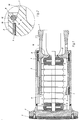
- the basic structure of a buffer is explained in more detail with reference to FIG. 1, wherein only deal with the parts relevant in connection with the invention becomes.
- the buffer has one to be fastened to the rail vehicle (not shown)
- Buffer sleeve 1 and a buffer plunger 2 on the front with a welded-on buffer plate 3 is provided.
- the front of the buffer plate 3 is formed by a wear plate 4 made of plastic.
- the buffer plunger 2 is axially displaceably guided on the buffer sleeve 1 by this radial from the buffer tappet 2 is included.
- Both the buffer sleeve 1 and the buffer plunger 2 are essentially hollow cylindrical design.
- the left end face 5 of the buffer sleeve 1 is used as a stop to limit the maximum insertion of the buffer plunger 2 which the buffer plunger 2 put on with the rear 6 of the buffer plate 3 can.
- the buffer plunger 2 is in such a way via a preloaded spring assembly 9 Buffer sleeve 1 supported that he counter to the spring force in the direction of the buffer sleeve 1 can be inserted.
- Buffer sleeve 1 supported that he counter to the spring force in the direction of the buffer sleeve 1 can be inserted.
- the latter provided with a collar 17 on the inside.
- To reduce the friction between the buffer sleeve 1 and the buffer plunger 2 are circular plastic elements 7 provided.
- the buffer sleeve 1 has a section 10 on its rear side on, whose diameter compared to the inner diameter of the buffer tappet 2 in the end area facing away from the buffer plate 3 by at least twice the radial height of the snap ring 8 is formed smaller. If the snap ring 8 like in the present example has a circular cross-section, is below the radial height Understand the diameter of the cross section of the snap ring 8.
- the snap ring 8 When installing the buffer, make sure that the snap ring 8 and only then is the buffer sleeve 1 pushed onto the buffer plunger 2. The Snap ring 8 is pushed down to section 10. Then the buffer pestle 2 overcoming the spring force to the right against the buffer sleeve 1 pressed that the groove provided for receiving the snap ring 8 located above section 10. Then the clamping ring 8 in a known Pressed together and in a recess in the buffer plunger 2 be snapped into place.
- the snap ring 8 is preferably with recesses (not drawn) provided on which a tool for compressing the Snap rings 8 can be attached.
- the height of the snap ring 8 is made smaller than the inner diameter of the buffer tappet 2 in the end area facing away from the buffer plate 3, on the one hand, enables that the snap ring 8 can be compressed as far as that Outside diameter is reduced so far that it fits into the corresponding groove in the buffer tappet 2 can be used. It also makes the harsh environmental conditions Taken into account by between the snap ring 8 and the Buffer sleeve 1 enough space remains so that the buffer plunger 2 even when dirty Buffer sleeve 1 can be easily moved to the right.
- FIG. 2 shows the snap ring 8 in an enlarged view compared to FIG. 1 together with the area surrounding the buffer sleeve 1 and the buffer plunger 2.
- the groove 12 can be seen, in which the snap ring 8 is fixed on the inside of the buffer plunger 2.
- the buffer sleeve 1 is with a provided on the outside circumferential projection 13, which as a stop is designed for the snap ring 8.
- This projection 13 has one with the shape of the snap ring 8 corresponding recess 14, the Snap ring 8, seen in cross section, is essentially round.
- the Buffer sleeve 1 is also essentially conical with the recess 14 provided towards section 15.
- This design ensures that the snap ring 8 when bumping against the elevation 13, that is at maximum Extending the buffer plunger 2 is held in position in the groove 12 because of Outside diameter of the buffer sleeve 1 in the region of the recess 14 practically Corresponds to the inner diameter of the clamping ring 8 and the latter thereby on its inside is supported.
- Fig. 3 shows an alternative embodiment of a buffer in a partially sectioned Presentation.
- the buffer sleeve 1a comprises the buffer tappet 2a radially, so that the buffer plunger 2a is guided in the buffer sleeve 1a.
- the snap ring 8a is in the end area facing the buffer plate 3a on the inside the buffer sleeve 1a arranged, while the buffer plunger 2a on the Outside with the projection designed as a stop for the snap ring 8a 13a is provided.
- This projection 13a is analogous to the previous embodiment again one that essentially corresponds to the shape of the snap ring 8a Recess 14a and is substantially conical the recess 14a tapered portion. Also in this embodiment of a buffer, make sure that when installing the Snap ring 8a and only then the buffer sleeve 1a pushed onto the buffer plunger 2a becomes.
- a buffer designed according to the invention can be manufactured inexpensively and assembled easily and quickly.
- Another advantage is that the buffer is easy to maintain. To do this, the buffer tappet 2, 2a must be adjusted against the spring preload to the right that the snap ring 8, 8a is above the section 10, 10a is located. In this position, the snap ring 8, 8a can be used by means of a suitable Tool are removed from the groove 12, 12a. Then the buffer tappet 2, 2a are withdrawn from the buffer sleeve 1, 1a, with all those requiring maintenance Parts are easily accessible.
Landscapes
- Engineering & Computer Science (AREA)
- Mechanical Engineering (AREA)
- Springs (AREA)
- Braking Arrangements (AREA)
- Snaps, Bayonet Connections, Set Pins, And Snap Rings (AREA)
- Vibration Dampers (AREA)
- Memory System Of A Hierarchy Structure (AREA)
Applications Claiming Priority (2)
| Application Number | Priority Date | Filing Date | Title |
|---|---|---|---|
| DE19907689 | 1999-02-23 | ||
| DE19907689 | 1999-02-23 |
Publications (2)
| Publication Number | Publication Date |
|---|---|
| EP1038751A1 true EP1038751A1 (fr) | 2000-09-27 |
| EP1038751B1 EP1038751B1 (fr) | 2001-12-12 |
Family
ID=7898514
Family Applications (1)
| Application Number | Title | Priority Date | Filing Date |
|---|---|---|---|
| EP00810060A Expired - Lifetime EP1038751B1 (fr) | 1999-02-23 | 2000-01-24 | Tampon pour véhicules ferroviaires |
Country Status (4)
| Country | Link |
|---|---|
| EP (1) | EP1038751B1 (fr) |
| AT (1) | ATE210574T1 (fr) |
| DE (1) | DE50000054D1 (fr) |
| ES (1) | ES2169718T3 (fr) |
Cited By (1)
| Publication number | Priority date | Publication date | Assignee | Title |
|---|---|---|---|---|
| EP1857343A2 (fr) | 2006-05-15 | 2007-11-21 | Schwab Verkehrstechnik AG | Tampon pour véhicules sur rail |
Citations (5)
| Publication number | Priority date | Publication date | Assignee | Title |
|---|---|---|---|---|
| DE2657837A1 (de) * | 1976-12-21 | 1978-06-22 | Ringfeder Gmbh | Vorrichtung zur federnden aufnahme von stosskraeften |
| DE2657836A1 (de) * | 1976-12-21 | 1978-06-22 | Ringfeder Gmbh | Vorrichtung zur federnden aufnahme von stosskraeften |
| US4175667A (en) * | 1976-10-15 | 1979-11-27 | Miner Enterprises, Inc. | Method of preshortening draft gear |
| DE9307051U1 (de) | 1993-05-10 | 1993-07-15 | Ringfeder Gmbh, 4150 Krefeld | Hülsenpuffer zur federnden Aufnahme von Stoßkräften, insbesondere für Schienenfahrzeuge |
| DE19813335A1 (de) * | 1998-03-26 | 1999-09-30 | Mannesmann Rexroth Ag | Pufferanordnung für Fahrzeuge |
-
2000
- 2000-01-24 AT AT00810060T patent/ATE210574T1/de not_active IP Right Cessation
- 2000-01-24 DE DE50000054T patent/DE50000054D1/de not_active Expired - Lifetime
- 2000-01-24 ES ES00810060T patent/ES2169718T3/es not_active Expired - Lifetime
- 2000-01-24 EP EP00810060A patent/EP1038751B1/fr not_active Expired - Lifetime
Patent Citations (5)
| Publication number | Priority date | Publication date | Assignee | Title |
|---|---|---|---|---|
| US4175667A (en) * | 1976-10-15 | 1979-11-27 | Miner Enterprises, Inc. | Method of preshortening draft gear |
| DE2657837A1 (de) * | 1976-12-21 | 1978-06-22 | Ringfeder Gmbh | Vorrichtung zur federnden aufnahme von stosskraeften |
| DE2657836A1 (de) * | 1976-12-21 | 1978-06-22 | Ringfeder Gmbh | Vorrichtung zur federnden aufnahme von stosskraeften |
| DE9307051U1 (de) | 1993-05-10 | 1993-07-15 | Ringfeder Gmbh, 4150 Krefeld | Hülsenpuffer zur federnden Aufnahme von Stoßkräften, insbesondere für Schienenfahrzeuge |
| DE19813335A1 (de) * | 1998-03-26 | 1999-09-30 | Mannesmann Rexroth Ag | Pufferanordnung für Fahrzeuge |
Cited By (2)
| Publication number | Priority date | Publication date | Assignee | Title |
|---|---|---|---|---|
| EP1857343A2 (fr) | 2006-05-15 | 2007-11-21 | Schwab Verkehrstechnik AG | Tampon pour véhicules sur rail |
| EP1857343A3 (fr) * | 2006-05-15 | 2008-10-08 | Schwab Verkehrstechnik AG | Tampon pour véhicules sur rail |
Also Published As
| Publication number | Publication date |
|---|---|
| EP1038751B1 (fr) | 2001-12-12 |
| ATE210574T1 (de) | 2001-12-15 |
| ES2169718T3 (es) | 2002-07-16 |
| DE50000054D1 (de) | 2002-01-24 |
Similar Documents
| Publication | Publication Date | Title |
|---|---|---|
| EP0766029B1 (fr) | Electrovanne et procédé de fabrication | |
| DE19580456C1 (de) | Transportsicherung bei einem Kettenspanner | |
| EP0649778B1 (fr) | Installation d'un filet de sécurité | |
| DE102005043234B4 (de) | Verfahren zur Herstellung eines elastomeren Buchsenlagers | |
| DE102005055071B4 (de) | Anschlagpuffer für eine Motorhaube von Automobilen | |
| EP1926641B1 (fr) | Dispositif essuie-glace, en particulier pour un vehicule a moteur | |
| WO2018041578A1 (fr) | Palier à patins oscillants | |
| EP1718507B1 (fr) | Systeme d'essuie-glaces pour vehicules et element de fixation pour un systeme de ce type | |
| DE102005009721B3 (de) | Lageranordnung | |
| EP0836018B1 (fr) | Joint à rotule et procédé de montage | |
| DE10253221B3 (de) | Haltekappe für einen Schutzbelag | |
| EP1458596B1 (fr) | Fixation d'un systeme d'essuie-glace | |
| EP1611367A1 (fr) | Palier a douille en caoutchouc a amortissement hydraulique pour un montage vertical | |
| EP1714053B1 (fr) | Poulie de deviation pour un dispositif d'entrainement de mecanisme de traction | |
| DE102009054830A1 (de) | Scheibenwischvorrichtung | |
| DE19811917A1 (de) | Kupplungsmechanismus für eine Zahnstange und deren Antriebsritzel | |
| EP0572821B1 (fr) | Colonne de direction de voiture | |
| DE19802442C2 (de) | Kabelkappe für eine Vorrichtung zur Bewegungsübertragung | |
| EP0475088B1 (fr) | Palier pour essieux de roues de remorque | |
| EP1038751B1 (fr) | Tampon pour véhicules ferroviaires | |
| DE19625999C2 (de) | Gewindespindelantrieb für eine Transportvorrichtung | |
| WO2005123467A1 (fr) | Ensemble pedale pour vehicule a moteur | |
| DE4420487C1 (de) | Hohlzapfengelenk | |
| DE102006031525B4 (de) | Lageraufnahme | |
| DE10062988B4 (de) | Hydraulische Betätigungseinrichtung an Kraftfahrzeugen |
Legal Events
| Date | Code | Title | Description |
|---|---|---|---|
| PUAI | Public reference made under article 153(3) epc to a published international application that has entered the european phase |
Free format text: ORIGINAL CODE: 0009012 |
|
| AK | Designated contracting states |
Kind code of ref document: A1 Designated state(s): AT BE CH CY DE DK ES FI FR GB GR IE IT LI LU MC NL PT SE |
|
| AX | Request for extension of the european patent |
Free format text: AL;LT;LV;MK;RO;SI |
|
| RIC1 | Information provided on ipc code assigned before grant |
Free format text: 7B 61G 11/18 A |
|
| 17P | Request for examination filed |
Effective date: 20001108 |
|
| TPAD | Observations filed by third parties |
Free format text: ORIGINAL CODE: EPIDOS TIPA |
|
| 17Q | First examination report despatched |
Effective date: 20010306 |
|
| AKX | Designation fees paid |
Free format text: AT BE CH CY DE DK ES FI FR GB GR IE IT LI LU MC NL PT SE |
|
| GRAG | Despatch of communication of intention to grant |
Free format text: ORIGINAL CODE: EPIDOS AGRA |
|
| GRAG | Despatch of communication of intention to grant |
Free format text: ORIGINAL CODE: EPIDOS AGRA |
|
| GRAH | Despatch of communication of intention to grant a patent |
Free format text: ORIGINAL CODE: EPIDOS IGRA |
|
| GRAH | Despatch of communication of intention to grant a patent |
Free format text: ORIGINAL CODE: EPIDOS IGRA |
|
| GRAA | (expected) grant |
Free format text: ORIGINAL CODE: 0009210 |
|
| AK | Designated contracting states |
Kind code of ref document: B1 Designated state(s): AT BE CH CY DE DK ES FI FR GB GR IE IT LI LU MC NL PT SE |
|
| PG25 | Lapsed in a contracting state [announced via postgrant information from national office to epo] |
Ref country code: GR Free format text: LAPSE BECAUSE OF FAILURE TO SUBMIT A TRANSLATION OF THE DESCRIPTION OR TO PAY THE FEE WITHIN THE PRESCRIBED TIME-LIMIT Effective date: 20011212 Ref country code: NL Free format text: LAPSE BECAUSE OF FAILURE TO SUBMIT A TRANSLATION OF THE DESCRIPTION OR TO PAY THE FEE WITHIN THE PRESCRIBED TIME-LIMIT Effective date: 20011212 Ref country code: IE Free format text: LAPSE BECAUSE OF FAILURE TO SUBMIT A TRANSLATION OF THE DESCRIPTION OR TO PAY THE FEE WITHIN THE PRESCRIBED TIME-LIMIT Effective date: 20011212 Ref country code: FI Free format text: LAPSE BECAUSE OF FAILURE TO SUBMIT A TRANSLATION OF THE DESCRIPTION OR TO PAY THE FEE WITHIN THE PRESCRIBED TIME-LIMIT Effective date: 20011212 |
|
| REF | Corresponds to: |
Ref document number: 210574 Country of ref document: AT Date of ref document: 20011215 Kind code of ref document: T |
|
| REG | Reference to a national code |
Ref country code: CH Ref legal event code: EP Ref country code: CH Ref legal event code: NV Representative=s name: ROTTMANN, ZIMMERMANN + PARTNER AG |
|
| REG | Reference to a national code |
Ref country code: GB Ref legal event code: IF02 |
|
| REG | Reference to a national code |
Ref country code: IE Ref legal event code: FG4D Free format text: GERMAN |
|
| PG25 | Lapsed in a contracting state [announced via postgrant information from national office to epo] |
Ref country code: LU Free format text: LAPSE BECAUSE OF NON-PAYMENT OF DUE FEES Effective date: 20020124 |
|
| REF | Corresponds to: |
Ref document number: 50000054 Country of ref document: DE Date of ref document: 20020124 |
|
| PG25 | Lapsed in a contracting state [announced via postgrant information from national office to epo] |
Ref country code: BE Free format text: LAPSE BECAUSE OF NON-PAYMENT OF DUE FEES Effective date: 20020131 Ref country code: CY Free format text: LAPSE BECAUSE OF FAILURE TO SUBMIT A TRANSLATION OF THE DESCRIPTION OR TO PAY THE FEE WITHIN THE PRESCRIBED TIME-LIMIT Effective date: 20020131 |
|
| PG25 | Lapsed in a contracting state [announced via postgrant information from national office to epo] |
Ref country code: DK Free format text: LAPSE BECAUSE OF FAILURE TO SUBMIT A TRANSLATION OF THE DESCRIPTION OR TO PAY THE FEE WITHIN THE PRESCRIBED TIME-LIMIT Effective date: 20020312 Ref country code: PT Free format text: LAPSE BECAUSE OF FAILURE TO SUBMIT A TRANSLATION OF THE DESCRIPTION OR TO PAY THE FEE WITHIN THE PRESCRIBED TIME-LIMIT Effective date: 20020312 |
|
| ET | Fr: translation filed | ||
| GBT | Gb: translation of ep patent filed (gb section 77(6)(a)/1977) |
Effective date: 20020228 |
|
| NLV1 | Nl: lapsed or annulled due to failure to fulfill the requirements of art. 29p and 29m of the patents act | ||
| REG | Reference to a national code |
Ref country code: ES Ref legal event code: FG2A Ref document number: 2169718 Country of ref document: ES Kind code of ref document: T3 |
|
| REG | Reference to a national code |
Ref country code: IE Ref legal event code: FD4D |
|
| BERE | Be: lapsed |
Owner name: SCHWAB VERKEHRSTECHNIK A.G. Effective date: 20020131 |
|
| PG25 | Lapsed in a contracting state [announced via postgrant information from national office to epo] |
Ref country code: MC Free format text: LAPSE BECAUSE OF NON-PAYMENT OF DUE FEES Effective date: 20020801 |
|
| PLBE | No opposition filed within time limit |
Free format text: ORIGINAL CODE: 0009261 |
|
| STAA | Information on the status of an ep patent application or granted ep patent |
Free format text: STATUS: NO OPPOSITION FILED WITHIN TIME LIMIT |
|
| 26N | No opposition filed | ||
| NLV1 | Nl: lapsed or annulled due to failure to fulfill the requirements of art. 29p and 29m of the patents act | ||
| PGFP | Annual fee paid to national office [announced via postgrant information from national office to epo] |
Ref country code: SE Payment date: 20071217 Year of fee payment: 9 |
|
| PGFP | Annual fee paid to national office [announced via postgrant information from national office to epo] |
Ref country code: AT Payment date: 20071212 Year of fee payment: 9 |
|
| EUG | Se: european patent has lapsed | ||
| REG | Reference to a national code |
Ref country code: CH Ref legal event code: NV Representative=s name: LUCHS & PARTNER PATENTANWAELTE |
|
| PG25 | Lapsed in a contracting state [announced via postgrant information from national office to epo] |
Ref country code: AT Free format text: LAPSE BECAUSE OF NON-PAYMENT OF DUE FEES Effective date: 20090124 |
|
| PG25 | Lapsed in a contracting state [announced via postgrant information from national office to epo] |
Ref country code: SE Free format text: LAPSE BECAUSE OF NON-PAYMENT OF DUE FEES Effective date: 20090125 |
|
| REG | Reference to a national code |
Ref country code: FR Ref legal event code: PLFP Year of fee payment: 17 |
|
| REG | Reference to a national code |
Ref country code: FR Ref legal event code: PLFP Year of fee payment: 18 |
|
| REG | Reference to a national code |
Ref country code: FR Ref legal event code: PLFP Year of fee payment: 19 |
|
| PGFP | Annual fee paid to national office [announced via postgrant information from national office to epo] |
Ref country code: FR Payment date: 20181213 Year of fee payment: 20 |
|
| PGFP | Annual fee paid to national office [announced via postgrant information from national office to epo] |
Ref country code: GB Payment date: 20190123 Year of fee payment: 20 Ref country code: IT Payment date: 20190121 Year of fee payment: 20 Ref country code: CH Payment date: 20190115 Year of fee payment: 20 Ref country code: ES Payment date: 20190201 Year of fee payment: 20 Ref country code: DE Payment date: 20190108 Year of fee payment: 20 |
|
| REG | Reference to a national code |
Ref country code: DE Ref legal event code: R071 Ref document number: 50000054 Country of ref document: DE |
|
| REG | Reference to a national code |
Ref country code: CH Ref legal event code: PL |
|
| REG | Reference to a national code |
Ref country code: GB Ref legal event code: PE20 Expiry date: 20200123 |
|
| PG25 | Lapsed in a contracting state [announced via postgrant information from national office to epo] |
Ref country code: GB Free format text: LAPSE BECAUSE OF EXPIRATION OF PROTECTION Effective date: 20200123 |
|
| REG | Reference to a national code |
Ref country code: ES Ref legal event code: FD2A Effective date: 20200723 |
|
| PG25 | Lapsed in a contracting state [announced via postgrant information from national office to epo] |
Ref country code: ES Free format text: LAPSE BECAUSE OF EXPIRATION OF PROTECTION Effective date: 20200125 |