EP1038672A2 - Dispositif de tension des plaques à imprimer dans des gorges de calage ayant une taille réduite - Google Patents
Dispositif de tension des plaques à imprimer dans des gorges de calage ayant une taille réduite Download PDFInfo
- Publication number
- EP1038672A2 EP1038672A2 EP00103375A EP00103375A EP1038672A2 EP 1038672 A2 EP1038672 A2 EP 1038672A2 EP 00103375 A EP00103375 A EP 00103375A EP 00103375 A EP00103375 A EP 00103375A EP 1038672 A2 EP1038672 A2 EP 1038672A2
- Authority
- EP
- European Patent Office
- Prior art keywords
- printing form
- cylinder
- holding
- printing
- tension shaft
- Prior art date
- Legal status (The legal status is an assumption and is not a legal conclusion. Google has not performed a legal analysis and makes no representation as to the accuracy of the status listed.)
- Granted
Links
Images


Classifications
-
- B—PERFORMING OPERATIONS; TRANSPORTING
- B41—PRINTING; LINING MACHINES; TYPEWRITERS; STAMPS
- B41F—PRINTING MACHINES OR PRESSES
- B41F27/00—Devices for attaching printing elements or formes to supports
- B41F27/12—Devices for attaching printing elements or formes to supports for attaching flexible printing formes
- B41F27/1262—Devices for attaching printing elements or formes to supports for attaching flexible printing formes without tensioning means
Definitions
- EP 0 639 454 B1 describes a device with a retractable hook for Holding a printing plate on a support cylinder in a rotary printing press and a rotary printing press with such a device is known become.
- the device for holding a printing plate on a support cylinder on a Rotary printing machine is located on a support cylinder with an outer to the axis of rotation of the support cylinder cylindrical peripheral surface and at least an inner longitudinal bore which is in the outer peripheral surface by means of a Longitudinal slot opens.
- hook-forming agents with at least one radially outer and to the axis of rotation of the support cylinder hooks pointing against the direction of rotation.
- means for Actuate the hook-forming means provided, which at least partially in the Bore of the support cylinder are arranged and are suitable for the hook in to move back and forth in a controlled manner. Between one in relation to the Direction of rotation of the support cylinder front end position to enable the Hooking or unhooking the rear end fold on the hook and one in with respect to the direction of rotation of the support cylinder rear end position in order to rear gusset hooked on the hook pulling force against the direction of rotation of the Exercise cylinder, the hook then into the interior of the slot is withdrawn with respect to the outer peripheral surface of the support cylinder.
- the hook-forming means are also embedded in the slot and the hook is standing in the front end position over the outer peripheral surface of the support cylinder about.
- the actuating means are suitable during the movement of the front end position to the rear end position the withdrawal of the hook in the slot and during the movement from the rear end position to the forward end position the protrusion of the hook with respect to the outer To cause peripheral surface of the support cylinder.
- the hook-forming means comprise at least one longitudinal blade having a first with respect to the Axis of rotation of the support cylinder has a radially inner end region, with a Tension rod is firmly connected inside the bore and a second longitudinal end portion, which is with respect to the axis of rotation of the support cylinder is located radially outside and which forms the hook, and the sheet between its first end region and its second end region elastically deformed.
- EP 0 678 383 A1 discloses a device for changing printing forms Rotary printing machines known. Both ends of a printing form are in the channel of a printing form cylinder, the surface of the printing form is wound around the printing form cylinder. According to this solution, one is a printing form A currently located on the printing form cylinder Device provided which is located on the printing form cylinder Printing form A takes up after this from the clamping devices of the Printing form cylinder is released and a device for feeding a new printing form B, which a new printing form to be applied to the Printing form cylinder transported.
- the device disclosed here draws is characterized in that at a short distance from the lateral surface of the Printing form cylinder horizontally movable holding elements of a leading edge Fix the printing form to be fed until remotely adjustable swiveling Holding means the front edge of the printing form B to be fed to the outer surface of the printing form cylinder.
- EP 0 734 859 A1 relates to a device for changing Printing forms.
- a swiveling printing form loading unit comprises both Printing form feeder as well as a printing form removal compartment.
- the Printing form loading unit is both in a working position on the channel one Printing form cylinder with clamping devices as well as in a loading position swiveling, in which the printing form loading unit from the working position withdrawn.
- the one that swivels into a vertical loading position Printing form loading unit can be pivoted onto a holding element, on which a Inlet area for a printing form and the printing form cylinder Conveyors for a to be applied to the printing form cylinder Printing form are provided.
- EP 0 741 021 A1 discloses a device for connecting holding elements with a traverse of a printing form cylinder.
- the device allows that Fixing a flexible printing form on the circumference of the printing form cylinder a rotary printing press, the leading edge of the flexible printing form engages over a front edge of a channel of the printing form cylinder and the Trailing edge of the flexible printing form by at least one on the crossbar
- Actuatable, resilient holding element can be fixed, which on the the periphery facing end has and is a hook-shaped projection characterized in that several holding elements can be arranged side by side can be positively locked to the crossbar with locking devices.
- the Holding elements can be inserted vertically in guides on the crossbar.
- the device can be used in the assembly of printing forms without Tool.
- the object of the invention based on the mounting of a finite pressure plate on one Printing form cylinder by hand or by means of automatic To facilitate or improve printing form feed devices.
- this object is achieved in that in one device for holding a printing form resiliently on the circumference of a printing form cylinder Mounted holding elements are provided, which are individually on a tension shaft are stored, the rear edge of a printing form when the tensioning shaft is actuated reach behind with play.
- the spring elements by means of individual support pins, one of each one Spring element is assigned, supported in the channel of the tension shaft.
- This solution allows the use of printing forms, the rear edge of which is not manufactured exactly was because the individual spring elements are irregularities on the Can adapt the printing form trailing edge more easily than, for example spring elements extending across the entire width.
- the actuating movement of the actuating unit for example as a pneumatic one Rapid cylinder with quick exhaust is formed using an adjusting lever transferred to the expansion shaft approach.
- the tension lever is from a bracket enclosed; the bracket can also serve to adjust the movement of the Limit the tension lever.
- the tension shaft on which the individual spring elements are mounted is in three Storage points, designed as annular surfaces, in Printing form cylinder mounted, on both faces of the cylinder and in the center, see above that smooth operation of the tension shaft is guaranteed. Via side Openings, on the cylinder, the tension shaft can be completely removed from the Printing form cylinders are pulled out to the side.
- the device of the invention can be particularly advantageous in Use printing form cylinders of rotary printing machines, be it sheet or Web-fed rotary printing machines.
- the low remaining non-printing The area around the tensioning channel saves the printers considerable paper costs.
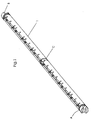
- the tension shaft 1 On the tension shaft 1, two outer bearing webs A, B are provided and one middle bearing web C.
- the middle bearing web C divides the tension shaft 1 into two sections, the two sections being of equal length.
- the tension shaft 1 is traversed along the axial extent by a recess in which individual spring elements 2 mounted next to one another on the tensioning shaft 1 are provided. These spring elements 2 are in the for clarity perspective view of FIG. 1 omitted.
- Fig. 2 shows an exploded view of the tension shaft in perspective Presentation.
- the tension shaft 1 comprises a recess extending in the axial direction, not shown here, in which individual spring elements 2 are embedded.
- the Spring elements 2 comprise both longitudinal slots D and themselves extending slots with which the spring elements 2 by means of stiff, in the Recess attached support pins 3 in the recess of the Printing form cylinder can be locked.
- the spring elements 2 are on the support pins 3 fastened with screws 5, which with a collar 6th are provided.
- the tension shaft 1 there are eight Spring elements 2 arranged side by side in the channel 19 of the Printing form cylinder 20 let in, which support the spring elements 2 Support pins 3 are received by the axially extending recess.
- the tensioning shaft 1 is provided on its end faces A, B with tensioning lugs 8, also referred to as torsion bars, provided in the illustrated Embodiment are designed as a clamping lug with a square profile. Triangular profiles or multi-wedge profiles that form a positive connection with an attachable clamping tool or a pneumatic or hydraulic one enable actuatable clamping tool are also conceivable.
- the one in Fig. 2 Positioning bar A is shown with an opening provided Bearing shield 7 enclosed, which on a recess of the end face of the Printing form cylinder 1 can be attached.
- the protruding from the bearing web A of the tension shaft 1 is 8 enclosed by an opening in the control lever 10.
- the actuating lever 10 is surrounded by a bracket 14 which is on the side of the Front side of the printing form cylinder can be screwed.
- an adjusting element 15 at its upper end provided which is provided with a spring 24, so that on the Top of the manual control element 15 provided a manual approach Adjustment of the control lever 10 and thus the tension shaft 1 remains possible.
- the Approach for the tool on the upper part of the hand control element 15 can For example, be designed as a socket wrench attachment - be it as a square, Hexagonal or multi-wedge profile.
- the one provided at the lower end, via a yoke with the lower part of the Actuating lever 10 on the cylinder end side of the actuating cylinder 11 is provided with a Provide quick exhaust 12 so that its operation is very quick can.
- the actuation time for the movement of the tension shaft 1 can thus be set to Minimum be reduced.
- Fig. 3 shows a cross section through the tension shaft 1 in a bit enlarged scale.
- the tension shaft 1 is in its axial extent with a recess provided, in which the support pins 3 are embedded, on which the Spring elements 2 are added.
- the individual support pins 3 are 3 penetrated by screws 5 with a collar element 6 are provided.
- the screws 5 extend into a thread that inside the tension shaft 1 is formed.
- the spring elements 2 are connected to the support pin 3.
- a tensioning lug 8 is formed in the center thereof, in the 3 as a square.
- Fig. 4 shows a perspective top view of a cylinder face of the Printing form cylinder.
- the clutch 23 is shown in front of it.
- the control lever 10 extends along the end face 21 of the printing form cylinder 20, the actuating lever 10 actuating actuator 11 is flanged in the lower region of the end face 21.
- the actuating unit 11, which is designed, for example, as a pneumatic actuating cylinder can be provided with a quick exhaust 12, so that the operating times drastically shorten.
- the tool attachment 19 is for a manual one Actuator provided, see also Fig. 5.
- a Tool can be a bolt provided below the starting point 15 twist, which is biased by a spring 24 with which the Tension shaft approach and the lever 10 is actuated.
- Fig. 5 shows the side view of the printing form cylinder end face 21 and in Detail three cross sections through the tension shaft bearing.
- the actuating lever 10 is connected at its lower end to the actuating unit 11 and includes with its upper end - as already explained above - the Tension shaft extension 8 of the tension shaft 1.
- the adjusting lever 10 is of a bracket 14 enclosed, with which the travel is limited.
- the top view of the End face 21 of the printing form cylinder 20 of the coupling 23 is mounted, which is located on a shoulder above the pin 22 of the printing form cylinder 20. In 5 in front of the coupling 23, the attachment is 9 shown, which partially hides the clutch 23.
- the detail according to FIG. 5 at the top left shows the view of the control lever 10 Removed clutch 23 above the cylinder pin 22.
- the adjusting lever 10 encloses the tension shaft extension 8 and includes one below the Unlocking element 15 lying spring 24 which the unlocking element 15th encloses.
- By turning the unlocking element 15 can Pressure drop in the pneumatic actuator 11, which is quite a Commercially available pneumatic cylinder can be an actuation of the tension shaft 1 be guaranteed.
- the actuating lever 10 removed, whereby the bearing plate 7 is visible. In this is a bearing web A Tension shaft 1 is added and can be used with a lubricating nipple Grease filling or the like can be provided to make it easy to move guarantee.
- the Channel 19 is from a left channel side wall 19.1 and one opposite channel side wall 19.2 limited, in which a Recess F is embedded.
- the tensioning channel 19 extends outward in a trapezoidal shape.
Landscapes
- Engineering & Computer Science (AREA)
- Mechanical Engineering (AREA)
- Supply, Installation And Extraction Of Printed Sheets Or Plates (AREA)
Applications Claiming Priority (4)
| Application Number | Priority Date | Filing Date | Title |
|---|---|---|---|
| DE19913701 | 1999-03-26 | ||
| DE19913701A DE19913701A1 (de) | 1999-03-26 | 1999-03-26 | Einrichtung zum Spannen von Druckformen in Spannkanälen reduzierter Größe |
| FR0000635A FR2791300B1 (fr) | 1999-03-26 | 2000-01-19 | Dispositif de fixation de plaques d'impression dans des canaux de fixation de grandeur reduite |
| FR0000635 | 2000-01-19 |
Publications (3)
| Publication Number | Publication Date |
|---|---|
| EP1038672A2 true EP1038672A2 (fr) | 2000-09-27 |
| EP1038672A3 EP1038672A3 (fr) | 2001-04-11 |
| EP1038672B1 EP1038672B1 (fr) | 2003-12-03 |
Family
ID=26052594
Family Applications (1)
| Application Number | Title | Priority Date | Filing Date |
|---|---|---|---|
| EP00103375A Expired - Lifetime EP1038672B1 (fr) | 1999-03-26 | 2000-02-23 | Dispositif de tension des plaques à imprimer dans des gorges de calage ayant une taille réduite |
Country Status (4)
| Country | Link |
|---|---|
| US (1) | US6601508B1 (fr) |
| EP (1) | EP1038672B1 (fr) |
| JP (1) | JP4921628B2 (fr) |
| AT (1) | ATE255502T1 (fr) |
Families Citing this family (4)
| Publication number | Priority date | Publication date | Assignee | Title |
|---|---|---|---|---|
| DE10342740A1 (de) * | 2003-09-16 | 2005-04-21 | Goss Int Montataire Sa | Verfahren zum Ändern des Befestigungszustands einer Druckform auf einem Druckformzylinder |
| DE102004034049A1 (de) * | 2004-07-13 | 2006-02-09 | Man Roland Druckmaschinen Ag | Formzylinder einer Rollenrotationsdruckmaschine |
| JP4699106B2 (ja) * | 2005-06-24 | 2011-06-08 | 三菱重工印刷紙工機械株式会社 | 保持装置 |
| US20080216691A1 (en) * | 2007-03-05 | 2008-09-11 | Stephens Ronald F | Printing plate lock mechanisms |
Citations (7)
| Publication number | Priority date | Publication date | Assignee | Title |
|---|---|---|---|---|
| US3727551A (en) * | 1971-07-22 | 1973-04-17 | North American Rockwell | Reversible lockup for flexible printing plate |
| US5213038A (en) * | 1991-09-19 | 1993-05-25 | Komori Corporation | Plate exchange apparatus for rotary press |
| EP0639454A1 (fr) * | 1993-08-20 | 1995-02-22 | Heidelberger Druckmaschinen Aktiengesellschaft | Dispositif à crochet escamotable pour maintenir une plaque d'impression sur un cylindre porte-plaque dans une imprimante rotative et imprimante rotative comportant un tel dispositif |
| EP0680826A2 (fr) * | 1994-05-04 | 1995-11-08 | MAN Roland Druckmaschinen AG | Dispositif pour fixer une plaque d'impression flexible |
| DE29600845U1 (de) * | 1996-01-19 | 1996-03-07 | MAN Roland Druckmaschinen AG, 63075 Offenbach | Vorrichtung zum Befestigen einer Bespannung auf einem Druckwerkzylinder |
| EP0741021A1 (fr) * | 1995-05-04 | 1996-11-06 | Heidelberger Druckmaschinen Aktiengesellschaft | Dispositif d'assemblage des dispositifs de serrage avec une traverse d'un cylindre de forme |
| DE19729375A1 (de) * | 1997-07-09 | 1999-01-14 | Ltg Lufttechnische Gmbh | Vorrichtung zum Befestigen einer biegsamen Platte auf dem Umfang des Zylinders einer Lackiermaschine |
Family Cites Families (12)
| Publication number | Priority date | Publication date | Assignee | Title |
|---|---|---|---|---|
| DE1198376B (de) * | 1964-04-29 | 1965-08-12 | Roland Offsetmaschf | Anordnung zum Befestigen des Gummituches auf dem Gummizylinder von Offsetdruckmaschinen |
| US3757691A (en) | 1972-06-12 | 1973-09-11 | North American Rockwell | Printing cylinder |
| DE4234332A1 (de) * | 1992-10-12 | 1994-04-14 | Heidelberger Druckmasch Ag | Aufspannvorrichtung zum Befestigen einer biegsamen Druckform auf der Mantelfläche eines Zylinders |
| FR2709091B1 (fr) | 1993-08-20 | 1995-11-10 | Heidelberg Harris Sa | Dispositif à lame interchangeable pour maintenir une plaque d'impression sur un cylindre porte-plaque dans une imprimante rotative, et outil de démontage de la lame. |
| DE4404758C2 (de) | 1994-02-15 | 1996-06-27 | Roland Man Druckmasch | Verfahren und Vorrichtung zum Wechseln der Bespannung eines Zylinders einer Rollenrotationsdruckmaschine |
| FR2718675B1 (fr) | 1994-04-18 | 1996-07-12 | Heidelberg Harris Sa | Dispositif d'échange de clichés de machines rotatives à imprimer. |
| DE19509563C2 (de) * | 1995-03-16 | 1997-01-23 | Koenig & Bauer Albert Ag | Zylinder mit einer Vorrichtung zum Spannen von Platten |
| FR2732267B1 (fr) | 1995-03-31 | 1997-06-20 | Heidelberg Harris Sa | Dispositif de changement de formes d'impression |
| JPH0966598A (ja) * | 1995-08-31 | 1997-03-11 | Komori Corp | 輪転印刷機の版取付構造 |
| FR2776566B1 (fr) * | 1998-03-27 | 2000-06-16 | Heidelberger Druckmasch Ag | Cylindre de groupe d'impression equipe d'une plaque d'impression a extremites coudees, se fixant sur lui, pour machines rotatives a imprimer |
| FR2776567B1 (fr) * | 1998-03-31 | 2000-06-16 | Heidelberger Druckmasch Ag | Dispositif de maintien d'une plaque d'impression sur un cylindre porte-plaque d'une machine d'impression rotative |
| DE10003937C2 (de) * | 2000-01-29 | 2003-02-27 | Roland Man Druckmasch | Vorrichtung zum Befestigen von biegsamen Druckformen |
-
2000
- 2000-02-23 AT AT00103375T patent/ATE255502T1/de not_active IP Right Cessation
- 2000-02-23 EP EP00103375A patent/EP1038672B1/fr not_active Expired - Lifetime
- 2000-03-27 JP JP2000086586A patent/JP4921628B2/ja not_active Expired - Fee Related
- 2000-03-27 US US09/536,170 patent/US6601508B1/en not_active Expired - Lifetime
Patent Citations (7)
| Publication number | Priority date | Publication date | Assignee | Title |
|---|---|---|---|---|
| US3727551A (en) * | 1971-07-22 | 1973-04-17 | North American Rockwell | Reversible lockup for flexible printing plate |
| US5213038A (en) * | 1991-09-19 | 1993-05-25 | Komori Corporation | Plate exchange apparatus for rotary press |
| EP0639454A1 (fr) * | 1993-08-20 | 1995-02-22 | Heidelberger Druckmaschinen Aktiengesellschaft | Dispositif à crochet escamotable pour maintenir une plaque d'impression sur un cylindre porte-plaque dans une imprimante rotative et imprimante rotative comportant un tel dispositif |
| EP0680826A2 (fr) * | 1994-05-04 | 1995-11-08 | MAN Roland Druckmaschinen AG | Dispositif pour fixer une plaque d'impression flexible |
| EP0741021A1 (fr) * | 1995-05-04 | 1996-11-06 | Heidelberger Druckmaschinen Aktiengesellschaft | Dispositif d'assemblage des dispositifs de serrage avec une traverse d'un cylindre de forme |
| DE29600845U1 (de) * | 1996-01-19 | 1996-03-07 | MAN Roland Druckmaschinen AG, 63075 Offenbach | Vorrichtung zum Befestigen einer Bespannung auf einem Druckwerkzylinder |
| DE19729375A1 (de) * | 1997-07-09 | 1999-01-14 | Ltg Lufttechnische Gmbh | Vorrichtung zum Befestigen einer biegsamen Platte auf dem Umfang des Zylinders einer Lackiermaschine |
Also Published As
| Publication number | Publication date |
|---|---|
| JP2000301694A (ja) | 2000-10-31 |
| EP1038672B1 (fr) | 2003-12-03 |
| ATE255502T1 (de) | 2003-12-15 |
| JP4921628B2 (ja) | 2012-04-25 |
| EP1038672A3 (fr) | 2001-04-11 |
| US6601508B1 (en) | 2003-08-05 |
Similar Documents
| Publication | Publication Date | Title |
|---|---|---|
| DE10058996C1 (de) | Vorrichtung zur Befestigung eines Aufzuges | |
| DE3723415A1 (de) | Verfahren und mechanismus zum anbauen und abbauen einer automobiltuer an einen bzw. von einem automobilkoerper | |
| EP1278636B1 (fr) | Dispositif pour fixer une plaque souple | |
| EP0606604B1 (fr) | Dipositif pour fixer des clichés souples sur le cylindre imprimeur d'une machine à imprimer | |
| EP0612616A2 (fr) | Cylindre porte-plaque aire dispositif semi-automatique de tension des plaques | |
| DE19924784C2 (de) | Vorrichtung zum Befestigen von biegsamen Platten auf einem Zylinder einer Rotationsdruckmaschine mit Drehrichtungsumkehr | |
| DE4444062C2 (de) | Vorrichtung zum Ausrichten einer Druckplatte auf einem Plattenzylinder einer Rotationsdruckmaschine | |
| DE4412085C2 (de) | Vorrichtung zum lösbaren Festsetzen von Wechselbehältern | |
| DE4427977A1 (de) | Vorrichtung mit einem zurückziehbaren Haken zum Halten einer Druckplatte auf einem Tragzylinder in einer Rotationsdruckmaschine und Rotationsdruckmaschine mit einer derartigen Vorrichtung | |
| EP1038672B1 (fr) | Dispositif de tension des plaques à imprimer dans des gorges de calage ayant une taille réduite | |
| DE69406099T2 (de) | Vorrichtung zur Erleichterung des Demontierens und Montierens von Reifen auf und von Radfelgen | |
| CH695213A5 (de) | Verfahren zum Ein- und Ausbau eines Zylinders einer Druckmaschine sowie Vorrichtung hierzu. | |
| DE4326251C2 (de) | Gummi-/Drucktuchzylinder | |
| EP0143257A1 (fr) | Raccordement d'outil d'une presse de découpage, notamment d'une presse de découpage à plateau revolver, pour le changement d'outil | |
| DE3430131A1 (de) | Bogenuebertragungszylinder in bogenrotationsdruckmaschinen | |
| DE19531024B4 (de) | Vorrichtung und Verfahren zum Anbringen einer Druckplatte auf einem Plattenzylinder einer Rotationsdruckpresse | |
| DE4428109A1 (de) | Vorrichtung mit austauschbaren Blatt zum Halten einer Druckplatte auf einem Tragzylinder in einer Rotationsdruckmaschine und Werkzeug zum Demontieren des Blattes | |
| DE19913701A1 (de) | Einrichtung zum Spannen von Druckformen in Spannkanälen reduzierter Größe | |
| WO2004020198A2 (fr) | Dispositif et procede pour faire appuyer un habillage contre le cylindre d'une machine d'impression au moyen d'elements d'appui | |
| EP1282519B1 (fr) | Cylindre avec un dispositif servant a presser un blanchet contre ce cylindre | |
| EP0473951A2 (fr) | Dispositif pour monter l'outil sur le porte-outil d'une presse à refouler | |
| DE19549707B4 (de) | Apparat und Verfahren zum Verriegeln einer Druckplatte einer Rotationsdruckpresse | |
| EP1834774B1 (fr) | Dispositif destiné à la fixation d'un habillage flexible sur un cylindre d'impression | |
| DE4326247A1 (de) | Spindel | |
| DE10024087C2 (de) | Vorrichtung zum Befestigen einer Druckplatte auf einem Zylinder einer Rotationsdruckmaschine |
Legal Events
| Date | Code | Title | Description |
|---|---|---|---|
| PUAI | Public reference made under article 153(3) epc to a published international application that has entered the european phase |
Free format text: ORIGINAL CODE: 0009012 |
|
| AK | Designated contracting states |
Kind code of ref document: A2 Designated state(s): AT BE CH CY DE DK ES FI FR GB GR IE IT LI LU MC NL PT SE |
|
| AX | Request for extension of the european patent |
Free format text: AL;LT;LV;MK;RO;SI |
|
| PUAL | Search report despatched |
Free format text: ORIGINAL CODE: 0009013 |
|
| AK | Designated contracting states |
Kind code of ref document: A3 Designated state(s): AT BE CH CY DE DK ES FI FR GB GR IE IT LI LU MC NL PT SE |
|
| AX | Request for extension of the european patent |
Free format text: AL;LT;LV;MK;RO;SI |
|
| 17P | Request for examination filed |
Effective date: 20010402 |
|
| AKX | Designation fees paid |
Free format text: AT BE CH CY DE DK ES FI FR GB GR IE IT LI LU MC NL PT SE |
|
| 17Q | First examination report despatched |
Effective date: 20020124 |
|
| GRAH | Despatch of communication of intention to grant a patent |
Free format text: ORIGINAL CODE: EPIDOS IGRA |
|
| GRAS | Grant fee paid |
Free format text: ORIGINAL CODE: EPIDOSNIGR3 |
|
| GRAA | (expected) grant |
Free format text: ORIGINAL CODE: 0009210 |
|
| AK | Designated contracting states |
Kind code of ref document: B1 Designated state(s): AT BE CH CY DE DK ES FI FR GB GR IE IT LI LU MC NL PT SE |
|
| PG25 | Lapsed in a contracting state [announced via postgrant information from national office to epo] |
Ref country code: IE Free format text: LAPSE BECAUSE OF FAILURE TO SUBMIT A TRANSLATION OF THE DESCRIPTION OR TO PAY THE FEE WITHIN THE PRESCRIBED TIME-LIMIT Effective date: 20031203 Ref country code: FI Free format text: LAPSE BECAUSE OF FAILURE TO SUBMIT A TRANSLATION OF THE DESCRIPTION OR TO PAY THE FEE WITHIN THE PRESCRIBED TIME-LIMIT Effective date: 20031203 Ref country code: NL Free format text: LAPSE BECAUSE OF FAILURE TO SUBMIT A TRANSLATION OF THE DESCRIPTION OR TO PAY THE FEE WITHIN THE PRESCRIBED TIME-LIMIT Effective date: 20031203 Ref country code: CY Free format text: LAPSE BECAUSE OF FAILURE TO SUBMIT A TRANSLATION OF THE DESCRIPTION OR TO PAY THE FEE WITHIN THE PRESCRIBED TIME-LIMIT Effective date: 20031203 |
|
| REG | Reference to a national code |
Ref country code: GB Ref legal event code: FG4D Free format text: NOT ENGLISH |
|
| REG | Reference to a national code |
Ref country code: CH Ref legal event code: EP |
|
| REG | Reference to a national code |
Ref country code: IE Ref legal event code: FG4D Free format text: GERMAN |
|
| REF | Corresponds to: |
Ref document number: 50004610 Country of ref document: DE Date of ref document: 20040115 Kind code of ref document: P |
|
| PG25 | Lapsed in a contracting state [announced via postgrant information from national office to epo] |
Ref country code: AT Free format text: LAPSE BECAUSE OF NON-PAYMENT OF DUE FEES Effective date: 20040223 Ref country code: LU Free format text: LAPSE BECAUSE OF NON-PAYMENT OF DUE FEES Effective date: 20040223 |
|
| PG25 | Lapsed in a contracting state [announced via postgrant information from national office to epo] |
Ref country code: BE Free format text: LAPSE BECAUSE OF NON-PAYMENT OF DUE FEES Effective date: 20040228 Ref country code: MC Free format text: LAPSE BECAUSE OF NON-PAYMENT OF DUE FEES Effective date: 20040228 |
|
| PG25 | Lapsed in a contracting state [announced via postgrant information from national office to epo] |
Ref country code: SE Free format text: LAPSE BECAUSE OF FAILURE TO SUBMIT A TRANSLATION OF THE DESCRIPTION OR TO PAY THE FEE WITHIN THE PRESCRIBED TIME-LIMIT Effective date: 20040303 Ref country code: DK Free format text: LAPSE BECAUSE OF FAILURE TO SUBMIT A TRANSLATION OF THE DESCRIPTION OR TO PAY THE FEE WITHIN THE PRESCRIBED TIME-LIMIT Effective date: 20040303 Ref country code: GR Free format text: LAPSE BECAUSE OF FAILURE TO SUBMIT A TRANSLATION OF THE DESCRIPTION OR TO PAY THE FEE WITHIN THE PRESCRIBED TIME-LIMIT Effective date: 20040303 |
|
| PG25 | Lapsed in a contracting state [announced via postgrant information from national office to epo] |
Ref country code: ES Free format text: LAPSE BECAUSE OF FAILURE TO SUBMIT A TRANSLATION OF THE DESCRIPTION OR TO PAY THE FEE WITHIN THE PRESCRIBED TIME-LIMIT Effective date: 20040314 |
|
| NLV1 | Nl: lapsed or annulled due to failure to fulfill the requirements of art. 29p and 29m of the patents act | ||
| GBT | Gb: translation of ep patent filed (gb section 77(6)(a)/1977) |
Effective date: 20040415 |
|
| REG | Reference to a national code |
Ref country code: IE Ref legal event code: FD4D |
|
| BERE | Be: lapsed |
Owner name: *HEIDELBERGER DRUCKMASCHINEN A.G. Effective date: 20040228 |
|
| ET | Fr: translation filed | ||
| PLBE | No opposition filed within time limit |
Free format text: ORIGINAL CODE: 0009261 |
|
| STAA | Information on the status of an ep patent application or granted ep patent |
Free format text: STATUS: NO OPPOSITION FILED WITHIN TIME LIMIT |
|
| RAP2 | Party data changed (patent owner data changed or rights of a patent transferred) |
Owner name: HEIDELBERG WEB SYSTEMS, S.A. |
|
| 26N | No opposition filed |
Effective date: 20040906 |
|
| REG | Reference to a national code |
Ref country code: GB Ref legal event code: 732E |
|
| REG | Reference to a national code |
Ref country code: FR Ref legal event code: TP |
|
| PG25 | Lapsed in a contracting state [announced via postgrant information from national office to epo] |
Ref country code: PT Free format text: LAPSE BECAUSE OF NON-PAYMENT OF DUE FEES Effective date: 20040503 |
|
| PGFP | Annual fee paid to national office [announced via postgrant information from national office to epo] |
Ref country code: GB Payment date: 20080227 Year of fee payment: 9 |
|
| GBPC | Gb: european patent ceased through non-payment of renewal fee |
Effective date: 20090223 |
|
| PG25 | Lapsed in a contracting state [announced via postgrant information from national office to epo] |
Ref country code: GB Free format text: LAPSE BECAUSE OF NON-PAYMENT OF DUE FEES Effective date: 20090223 |
|
| PGFP | Annual fee paid to national office [announced via postgrant information from national office to epo] |
Ref country code: IT Payment date: 20110224 Year of fee payment: 12 Ref country code: CH Payment date: 20110223 Year of fee payment: 12 |
|
| REG | Reference to a national code |
Ref country code: CH Ref legal event code: PL |
|
| PG25 | Lapsed in a contracting state [announced via postgrant information from national office to epo] |
Ref country code: CH Free format text: LAPSE BECAUSE OF NON-PAYMENT OF DUE FEES Effective date: 20120229 Ref country code: LI Free format text: LAPSE BECAUSE OF NON-PAYMENT OF DUE FEES Effective date: 20120229 |
|
| PG25 | Lapsed in a contracting state [announced via postgrant information from national office to epo] |
Ref country code: IT Free format text: LAPSE BECAUSE OF NON-PAYMENT OF DUE FEES Effective date: 20120223 |
|
| REG | Reference to a national code |
Ref country code: FR Ref legal event code: PLFP Year of fee payment: 17 |
|
| REG | Reference to a national code |
Ref country code: FR Ref legal event code: PLFP Year of fee payment: 18 |
|
| PGFP | Annual fee paid to national office [announced via postgrant information from national office to epo] |
Ref country code: DE Payment date: 20170227 Year of fee payment: 18 Ref country code: FR Payment date: 20170223 Year of fee payment: 18 |
|
| REG | Reference to a national code |
Ref country code: DE Ref legal event code: R082 Ref document number: 50004610 Country of ref document: DE Representative=s name: PATENTANWAELTE ISENBRUCK BOESL HOERSCHLER LLP, DE Ref country code: DE Ref legal event code: R081 Ref document number: 50004610 Country of ref document: DE Owner name: GOSS INTERNATIONAL LLC (N. D. GES. D. STAATES , US Free format text: FORMER OWNER: GOSS INTERNATIONAL MONTATAIRE S.A., MONTATAIRE, FR |
|
| REG | Reference to a national code |
Ref country code: DE Ref legal event code: R119 Ref document number: 50004610 Country of ref document: DE |
|
| REG | Reference to a national code |
Ref country code: FR Ref legal event code: ST Effective date: 20181031 |
|
| PG25 | Lapsed in a contracting state [announced via postgrant information from national office to epo] |
Ref country code: DE Free format text: LAPSE BECAUSE OF NON-PAYMENT OF DUE FEES Effective date: 20180901 |
|
| PG25 | Lapsed in a contracting state [announced via postgrant information from national office to epo] |
Ref country code: FR Free format text: LAPSE BECAUSE OF NON-PAYMENT OF DUE FEES Effective date: 20180228 |