EP1037701B1 - Method and apparatus for mixing - Google Patents
Method and apparatus for mixing Download PDFInfo
- Publication number
- EP1037701B1 EP1037701B1 EP98938539A EP98938539A EP1037701B1 EP 1037701 B1 EP1037701 B1 EP 1037701B1 EP 98938539 A EP98938539 A EP 98938539A EP 98938539 A EP98938539 A EP 98938539A EP 1037701 B1 EP1037701 B1 EP 1037701B1
- Authority
- EP
- European Patent Office
- Prior art keywords
- liquid
- vessel
- flow
- rotating means
- mechanical rotating
- Prior art date
- Legal status (The legal status is an assumption and is not a legal conclusion. Google has not performed a legal analysis and makes no representation as to the accuracy of the status listed.)
- Expired - Lifetime
Links
- 238000000034 method Methods 0.000 title claims abstract description 27
- 239000007788 liquid Substances 0.000 claims abstract description 59
- 239000002245 particle Substances 0.000 claims abstract description 13
- 239000012716 precipitator Substances 0.000 claims description 45
- 239000002002 slurry Substances 0.000 claims description 15
- 229910001679 gibbsite Inorganic materials 0.000 claims description 8
- 230000008569 process Effects 0.000 claims description 5
- 230000001939 inductive effect Effects 0.000 claims description 3
- 230000001376 precipitating effect Effects 0.000 claims description 3
- 238000005273 aeration Methods 0.000 abstract 1
- 239000013078 crystal Substances 0.000 description 6
- 239000012530 fluid Substances 0.000 description 5
- 239000011324 bead Substances 0.000 description 4
- 238000004519 manufacturing process Methods 0.000 description 4
- 239000000047 product Substances 0.000 description 4
- 230000008901 benefit Effects 0.000 description 3
- 238000001816 cooling Methods 0.000 description 3
- 239000002244 precipitate Substances 0.000 description 3
- 230000009467 reduction Effects 0.000 description 3
- 239000007787 solid Substances 0.000 description 3
- 239000000725 suspension Substances 0.000 description 3
- 238000004131 Bayer process Methods 0.000 description 2
- 239000004793 Polystyrene Substances 0.000 description 2
- 238000005054 agglomeration Methods 0.000 description 2
- 230000002776 aggregation Effects 0.000 description 2
- 239000006185 dispersion Substances 0.000 description 2
- 230000006872 improvement Effects 0.000 description 2
- 229920002223 polystyrene Polymers 0.000 description 2
- 238000001556 precipitation Methods 0.000 description 2
- 238000005276 aerator Methods 0.000 description 1
- 238000013019 agitation Methods 0.000 description 1
- PNEYBMLMFCGWSK-UHFFFAOYSA-N aluminium oxide Inorganic materials [O-2].[O-2].[O-2].[Al+3].[Al+3] PNEYBMLMFCGWSK-UHFFFAOYSA-N 0.000 description 1
- 229910001570 bauxite Inorganic materials 0.000 description 1
- 230000009286 beneficial effect Effects 0.000 description 1
- 238000004140 cleaning Methods 0.000 description 1
- 230000008021 deposition Effects 0.000 description 1
- 238000010586 diagram Methods 0.000 description 1
- 230000000694 effects Effects 0.000 description 1
- 239000000463 material Substances 0.000 description 1
- 239000000203 mixture Substances 0.000 description 1
- 238000012986 modification Methods 0.000 description 1
- 230000004048 modification Effects 0.000 description 1
- 238000010926 purge Methods 0.000 description 1
- 238000011084 recovery Methods 0.000 description 1
- 239000011343 solid material Substances 0.000 description 1
- 239000004449 solid propellant Substances 0.000 description 1
- XLYOFNOQVPJJNP-UHFFFAOYSA-N water Substances O XLYOFNOQVPJJNP-UHFFFAOYSA-N 0.000 description 1
Images

Classifications
-
- B—PERFORMING OPERATIONS; TRANSPORTING
- B01—PHYSICAL OR CHEMICAL PROCESSES OR APPARATUS IN GENERAL
- B01F—MIXING, e.g. DISSOLVING, EMULSIFYING OR DISPERSING
- B01F27/00—Mixers with rotary stirring devices in fixed receptacles; Kneaders
- B01F27/80—Mixers with rotary stirring devices in fixed receptacles; Kneaders with stirrers rotating about a substantially vertical axis
-
- B—PERFORMING OPERATIONS; TRANSPORTING
- B01—PHYSICAL OR CHEMICAL PROCESSES OR APPARATUS IN GENERAL
- B01F—MIXING, e.g. DISSOLVING, EMULSIFYING OR DISPERSING
- B01F23/00—Mixing according to the phases to be mixed, e.g. dispersing or emulsifying
- B01F23/50—Mixing liquids with solids
- B01F23/53—Mixing liquids with solids using driven stirrers
-
- B—PERFORMING OPERATIONS; TRANSPORTING
- B01—PHYSICAL OR CHEMICAL PROCESSES OR APPARATUS IN GENERAL
- B01F—MIXING, e.g. DISSOLVING, EMULSIFYING OR DISPERSING
- B01F23/00—Mixing according to the phases to be mixed, e.g. dispersing or emulsifying
- B01F23/40—Mixing liquids with liquids; Emulsifying
- B01F23/43—Mixing liquids with liquids; Emulsifying using driven stirrers
-
- B—PERFORMING OPERATIONS; TRANSPORTING
- B01—PHYSICAL OR CHEMICAL PROCESSES OR APPARATUS IN GENERAL
- B01F—MIXING, e.g. DISSOLVING, EMULSIFYING OR DISPERSING
- B01F23/00—Mixing according to the phases to be mixed, e.g. dispersing or emulsifying
- B01F23/50—Mixing liquids with solids
-
- B—PERFORMING OPERATIONS; TRANSPORTING
- B01—PHYSICAL OR CHEMICAL PROCESSES OR APPARATUS IN GENERAL
- B01F—MIXING, e.g. DISSOLVING, EMULSIFYING OR DISPERSING
- B01F27/00—Mixers with rotary stirring devices in fixed receptacles; Kneaders
- B01F27/05—Stirrers
- B01F27/11—Stirrers characterised by the configuration of the stirrers
- B01F27/111—Centrifugal stirrers, i.e. stirrers with radial outlets; Stirrers of the turbine type, e.g. with means to guide the flow
- B01F27/1111—Centrifugal stirrers, i.e. stirrers with radial outlets; Stirrers of the turbine type, e.g. with means to guide the flow with a flat disc or with a disc-like element equipped with blades, e.g. Rushton turbine
-
- B—PERFORMING OPERATIONS; TRANSPORTING
- B01—PHYSICAL OR CHEMICAL PROCESSES OR APPARATUS IN GENERAL
- B01F—MIXING, e.g. DISSOLVING, EMULSIFYING OR DISPERSING
- B01F27/00—Mixers with rotary stirring devices in fixed receptacles; Kneaders
- B01F27/80—Mixers with rotary stirring devices in fixed receptacles; Kneaders with stirrers rotating about a substantially vertical axis
- B01F27/81—Mixers with rotary stirring devices in fixed receptacles; Kneaders with stirrers rotating about a substantially vertical axis the stirrers having central axial inflow and substantially radial outflow
-
- B—PERFORMING OPERATIONS; TRANSPORTING
- B01—PHYSICAL OR CHEMICAL PROCESSES OR APPARATUS IN GENERAL
- B01F—MIXING, e.g. DISSOLVING, EMULSIFYING OR DISPERSING
- B01F25/00—Flow mixers; Mixers for falling materials, e.g. solid particles
- B01F2025/91—Direction of flow or arrangement of feed and discharge openings
- B01F2025/913—Vortex flow, i.e. flow spiraling in a tangential direction and moving in an axial direction
Definitions
- This invention relates to a method and to an apparatus for mixing liquids or liquid with particles to form slurries and the like.
- the apparatus of the present invention is suitable for mixing one liquid with another or mixing liquid with particles to form both homogeneous suspensions as well as mixtures in which not all of the particles are fully suspended.
- the invention is intended for applications where entrainment of gas from the liquid surface during mixing is undesirable and to be avoided.
- Apparatus for mixing of this type has a number of applications in a wide variety of industrial processes.
- One such application is agitated precipitators used in the process of precipitating crystals from a supersaturated liquor.
- Precipitators of this type are used in a number of industrial processes. The invention will hereinafter be specifically described with reference to this application but it will be readily appreciated that the scope of the invention is not limited to this particular application.
- One well known agitating precipitator is the Gibbsite precipitator used in the Bayer process to produce alumina hydrate from bauxite.
- Existing Gibbsite precipitators comprise a large vessel with a centrally disposed draft tube. An impeller is rotationally driven in the draft tube to provide a vertical circulation in the precipitator. In some cases baffles are provided around the sides of the vessel to prevent swirling or rotational flow in the slurry which otherwise impairs the desired vertical circulation.
- Existing Gibbsite precipitators use a large amount of input power to achieve the required circulation. Additionally, one of the objects of the precipitation process is to produce large crystal size in the precipitate.
- GB 2 190 305 discloses a conical centrifugal mixing impeller which provides a more efficient purging circulatory flow for destratification of fluids and solid-fuel suspension.
- the mixing impeller operates by taking fluid in through an open end and blades of the impeller scoop fluid from the inside of the impeller to force the fluid out and upwardly of openings between circumferentially attached blades.
- the impeller In a container the impeller generates an outwardly and upwardly directed flow which descends toward the container edges before being drawn inwardly to the impeller. The flow is similar to that in the above described precipitator and prone to the same problems.
- US 5,261,745 also describes a frusto-conical impeller mixing located near the bottom of a container.
- the impeller establishes a flow pattern in which the liquid is directed vertically downwardly around the outer periphery of the container to the impeller and then swirled upwardly from the impeller at the center axis of the container.
- DE 2 714 308 discloses an aerator for turning over and ventilaling liquids.
- the prevent invention provides a method and apparatus as defined in the claims.
- the rotational flow is preferably about zero at the centre of the inner annular region and greatest toward the outer edge of that region.
- the mechanical rotating means inducing the rotational flow includes a paddle or impeller.
- the paddle or impeller preferably rotates about a central axis.
- the paddle or impeller preferably only operates in the central region of the vessel.
- the blades of the paddle or impeller extend from a central hub or are otherwise outwardly offset from the axis of rotation.
- the vessel preferably has a circular cross-section.
- a conical base section joins the containing wall toward the lower end of the vessel.
- the base is flat.
- the rotational speed of the paddle or impeller used to induce the flow is selected to achieve the desired flow velocities.
- the liquid velocity adjacent the containing wall (outside the boundary layer) is between about 0.3m/s and 1m/s. Preferably this velocity is greater than 0.5m/s. In aluminia precipitators this has been found to ensure there is no scale build up on the precipitator walls.
- Maximum liquid tangential velocity in this inner core is preferably about 3 times the velocity adjacent the containing wall.
- the present invention has particular application to vessels that have a height equal to or greater than the diameter of the vessel.
- the present invention has been found to provide satisfactory mixing in vessels having heights equal to and up to four times the diameter. Many prior art mixing devices are unable to provide satisfactory mixing in these configurations.
- the apparatus includes means to provide a through flow of liquid through the vessel.
- the through flow enhances the rotation of the liquid in the vessel.
- a precipitator including a vessel having a smoothly continuous vertical wall at least in a horizontal direction to contain a slurry, mechanical rotating means disposed in the upper part of said vessel and submerged in the slurry to induce a rotational flow in the slurry directed radially outward from the centre of the vessel to establish a swirling flow of the slurry through the vessel characterised by an outer annular region of downwardly moving moderate rotational flow adj acent the vertical wall, an inward flow across the bottom of the vessel, and an inner core region of upwardly moving rapid rotational flow about the centre of the vessel extending substantially from the bottom of the vessel to the mechanical rotating means.
- Also another specific application is a method of precipitating from a slurry including the steps of placing the slurry in a vessel having a smoothly continuous vertical wall at least in a horizontal direction, inducing in the upper part of the vessel with mechanical rotating means submerged in the slurry a rotational flow in the slurry directed radially outwardly from the centre of the vessel to establish a swirling flow through the vessel characterised by an outer annular region of downwardly moving moderate rotational flow adjacent the vertical wall, an inward flow across the bottom of the vessel, and an inner core region of upwardly moving rapid rotational flow about the centre of the vessel extending substantially from the bottom of the vessel to the mechanical rotating means.
- this invention it is possible to operate the mixing apparatus on a non-continuous basis. This can be achieved by operating the mechanical rotating means used to induce the flow for example until an equilibrium is reached and then allowing the momentum of the liquid to continue mixing until rotation decays to a predetermined level or for a set period at which time the paddle or a propeller is again operated. This process can allow a considerable reduction in power requirements particularly if it is possible to minimise the amount of time that power is required to be delivered during periods of peak cost of electrical power.
- the input power to the precipitator is less than 20 Watts/cubic metre. Power inputs as low as 7 or 8 Watts/cubic metre can maintain the suspension and mixing performance.
- a further advantage of the invention is that solid material which would settle at the bottom of the vessel following a shutdown is more easily resuspended.
- the method and apparatus of this invention will be described in relation to a laboratory scale version of a precipitator. This description is for the purposes of illustration only. A commercial precipitator for use in the Bayer process has also been built. The commercial version of the apparatus is approximately 11 metres in diameter and has a height of around 28 metres. This corresponds to a volume of about 2.7 megalitres. This description is also by way of example only.
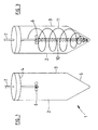
- the precipitator 1 of this invention comprises a vessel 2 formed by a smooth walled vertical cylinder 3 having an upper end 4 and a conical bottom 5.
- a Rushton turbine 6 is mounted on a shaft 7 for rotation by a drive motor (not shown).
- a laboratory scale version of the precipitator has been built utilising the configuration shown in Figure 1 .
- the laboratory version also includes means to introduce a through flow of slurry in the vessel such as would be required in an industrial precipitator. The through flow is pumped from underneath the turbine 6 and returned to the vessel so that it enhances the swirling flow in the tank. This is achieved by directing the inflow and outflow channels tangentially or near tangentially so that the inflow and outflow are substantially in the direction of rotation.
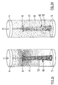
- Figures 2a to 2d show dispersion patterns of spherical polystyrene beads 8 in a liquid 9 in a hydrodynamic test rig.
- the test rig is generally similar to the arrangement described in relation to Figure 1 without the conical base 5.
- the patterns shown in Figure 2 are without any through flow of liquid.
- the steady rotational speed of the turbine 6 used in the test rig shown in Figure 2 is 200 rpm.
- the test rig clearly shows the beads 8 being suspended from the bottom 5 of the vessel 2 in a column or core 10 stretching all the way up to the turbine 6.
- the beads 8 are deflected towards the outer wall 3 of the vessel 2 and returned to the bottom in an outer annulus 11 adjacent wall 3 along a spiral path and with a moderate rotational flow.
- the particles 8 are found to predominate in a thin annulus 12 at the outer edge of the core 10 with little or no particles located near the axis of symmetry of the test rig.
- the vertical motion and the rotational flow of particles 8 located in the outer annular region 12 of the core 10 is very high while the motion of liquid near the axis of symmetry is relatively low.
- Figure 3 shows a schematic depiction of the flows induced in the precipitator configuration of Figure 1 .
Landscapes
- Chemical & Material Sciences (AREA)
- Chemical Kinetics & Catalysis (AREA)
- Dispersion Chemistry (AREA)
- Mixers Of The Rotary Stirring Type (AREA)
Applications Claiming Priority (5)
| Application Number | Priority Date | Filing Date | Title |
|---|---|---|---|
| AUPO8656A AUPO865697A0 (en) | 1997-08-19 | 1997-08-19 | Swirling precipitator |
| AUPO865697 | 1997-08-19 | ||
| AUPP2686A AUPP268698A0 (en) | 1998-03-31 | 1998-03-31 | Apparatus for mixing fluids |
| AUPP268698 | 1998-03-31 | ||
| PCT/AU1998/000661 WO1999008781A1 (en) | 1997-08-19 | 1998-08-19 | Method and apparatus for mixing |
Publications (3)
| Publication Number | Publication Date |
|---|---|
| EP1037701A1 EP1037701A1 (en) | 2000-09-27 |
| EP1037701A4 EP1037701A4 (en) | 2006-09-20 |
| EP1037701B1 true EP1037701B1 (en) | 2010-01-06 |
Family
ID=25645579
Family Applications (1)
| Application Number | Title | Priority Date | Filing Date |
|---|---|---|---|
| EP98938539A Expired - Lifetime EP1037701B1 (en) | 1997-08-19 | 1998-08-19 | Method and apparatus for mixing |
Country Status (12)
| Country | Link |
|---|---|
| US (1) | US6467947B1 (enExample) |
| EP (1) | EP1037701B1 (enExample) |
| JP (1) | JP2001514958A (enExample) |
| KR (1) | KR100534290B1 (enExample) |
| CN (1) | CN1138586C (enExample) |
| AT (1) | ATE454207T1 (enExample) |
| BR (1) | BR9811243A (enExample) |
| CA (1) | CA2300872C (enExample) |
| DE (1) | DE69841440D1 (enExample) |
| ES (1) | ES2344722T3 (enExample) |
| RU (1) | RU2216393C2 (enExample) |
| WO (1) | WO1999008781A1 (enExample) |
Families Citing this family (12)
| Publication number | Priority date | Publication date | Assignee | Title |
|---|---|---|---|---|
| US9044719B2 (en) * | 2007-12-21 | 2015-06-02 | Philadelphia Mixing Solutions, Ltd. | Method and apparatus for mixing |
| JP2011510813A (ja) * | 2008-02-08 | 2011-04-07 | ピュラック バイオケム ビー.ブイ. | ボルテックスミキサーおよび過飽和溶液またはスラリーを得る方法 |
| US8771524B2 (en) * | 2008-02-08 | 2014-07-08 | Purac Biochem B.V. | Vortex mixer and method of obtaining a supersaturated solution or slurry |
| CN102173489A (zh) * | 2011-03-02 | 2011-09-07 | 苏州顶裕节能设备有限公司 | 一种用于水处理的混合反应器 |
| RU2563496C2 (ru) * | 2013-11-29 | 2015-09-20 | Федеральное государственное бюджетное образовательное учреждение высшего профессионального образования "Московский государственный университет имени М.В. Ломоносова" (МГУ) | Способ механического перемешивания высоковязких жидкостей |
| RU2589485C2 (ru) * | 2014-04-16 | 2016-07-10 | Федеральное государственное бюджетное образовательное учреждение высшего образования "Московский государственный университет имени М.В. Ломоносова" (МГУ) | Способ бестранспортного перемешивания жидкостей |
| AU2016248111A1 (en) * | 2015-04-13 | 2017-11-02 | Virginia Tech Intellectual Properties, Inc. | Apparatus for dewatering and demineralization of fine particles |
| CN104959066B (zh) * | 2015-06-12 | 2019-01-18 | 中国核电工程有限公司 | 一种用于核废物处理的搅拌桨及搅拌装置 |
| JP6691654B2 (ja) * | 2016-01-27 | 2020-05-13 | 月島機械株式会社 | 粒子の製造装置及び粒子の製造方法 |
| CN110869112B (zh) | 2017-07-17 | 2021-11-26 | 联邦科学与工业研究组织 | 混合设备和操作方法 |
| CN110067010A (zh) * | 2019-06-13 | 2019-07-30 | 重庆科技学院 | 一种铜粉制备装置及制备方法 |
| JP2022083470A (ja) * | 2020-11-25 | 2022-06-06 | 三広アステック株式会社 | 粒子の滞留を改善した撹拌装置 |
Citations (1)
| Publication number | Priority date | Publication date | Assignee | Title |
|---|---|---|---|---|
| DE2714308A1 (de) * | 1977-03-31 | 1978-10-05 | Horst Ing Grad Schade | Belueftungseinrichtung zum umwaelzen und belueften von fluessigkeiten |
Family Cites Families (39)
| Publication number | Priority date | Publication date | Assignee | Title |
|---|---|---|---|---|
| DE5751C (de) * | H. BOEGER, in Firma: FRANLFURTER GUMMI-WAAREN-FABRIK, BOEGER, KOEBIG & BERGEON in Gelnhausen | Reibgummi mit Hartgummihülse | ||
| US1008010A (en) * | 1910-07-21 | 1911-11-07 | Warren Paint Company | Agitator. |
| US1786009A (en) * | 1928-06-13 | 1930-12-23 | Maschf Augsburg Nuernberg Ag | Apparatus for mixing liquids |
| US2072082A (en) * | 1936-02-27 | 1937-03-02 | Hargett Butts Corp | Liquid cooler |
| US2269736A (en) * | 1940-09-06 | 1942-01-13 | Leon Finch Ltd | Dispensing device |
| GB562921A (en) * | 1942-01-16 | 1944-07-21 | Du Pont | Centrifugal homogeniser |
| US2530814A (en) * | 1945-10-12 | 1950-11-21 | Schenley Ind Inc | Apparatus for aerating liquids |
| US2622943A (en) * | 1949-02-23 | 1952-12-23 | Universal Oil Prod Co | Bearing and seal device for stirrer shafts |
| US2875897A (en) * | 1953-06-22 | 1959-03-03 | Booth Lionel Earl | Flotation machine |
| US3111305A (en) * | 1960-09-22 | 1963-11-19 | Chemineer | High shear impeller |
| US3182970A (en) * | 1961-11-03 | 1965-05-11 | Hayward Tyler & Company Ltd | Stirrers or mixers |
| FR83287E (fr) * | 1963-03-19 | 1964-07-17 | Appareillage centrifuge pour la mise en contact intime et instantanée de matières diverses, fluides, gazeuses ou solides | |
| DE1457141A1 (de) * | 1964-10-10 | 1968-12-19 | Gustav Spangenberg Gmbh Maschi | Misch- und Dispergiermaschine |
| CH510453A (de) * | 1970-06-16 | 1971-07-31 | Koppers Gmbh Heinrich | Kreiselbelüfter zum Sauerstoffeintrag in Flüssigkeiten |
| FR2236550A1 (en) * | 1973-07-09 | 1975-02-07 | Bard Max | Turbine mixer - with pump for distributing contents to control vortex |
| US4256406A (en) * | 1979-09-19 | 1981-03-17 | Somerville Robert L | Agitator and driving means therefor |
| SU915923A1 (ru) * | 1980-03-31 | 1982-03-30 | Eduard A Vasiltsov | ЦИРКУЛЯЦИ&ННЫЙ АППАРАТ1 |
| BE884216A (nl) * | 1980-07-08 | 1980-11-03 | Haegeman Johny H | Inrichting voor het mengen van gas met vloeistof of omgekeerd en voor het ontgassen van een vloeistof |
| FR2533906A1 (fr) * | 1982-09-30 | 1984-04-06 | Rhone Poulenc Spec Chim | Procede et dispositif pour la preparation de silane pur par reaction de chlorosilanes avec l'hydrure de lithium |
| US4451155A (en) * | 1983-01-20 | 1984-05-29 | A. R. Wilfley And Sons, Inc. | Mixing device |
| US4630932A (en) * | 1986-02-10 | 1986-12-23 | Revelli Anthony J | Dispersing apparatus with wire wheel impeller |
| CA1259068A (en) * | 1986-05-07 | 1989-09-05 | Bach Systems Inc. | Spider mounted centrifugal mixing impeller |
| JPS63104605A (ja) * | 1986-10-23 | 1988-05-10 | Sakito Seien Kk | 育晶器付晶析装置において大粒の結晶を製造する方法 |
| FI86601C (fi) | 1987-10-21 | 1992-09-25 | Outokumpu Oy | Saett att aostadkomma dubbelcirkulationsfloede och apparatur daertill. |
| DE3821033A1 (de) * | 1988-06-22 | 1989-12-28 | Huels Chemische Werke Ag | Ruehrkessel mit radial foerderndem ruehrer und mindestens einem stromstoerer sowie verfahren zum durchmischen von fluessigkeiten mit hilfe dieses ruehrkessels |
| SU1724342A1 (ru) * | 1989-06-06 | 1992-04-07 | Днепропетровский химико-технологический институт | Смеситель дл размывани осадка твердых частиц |
| CA2044706C (en) * | 1990-06-15 | 2003-02-25 | Michael Midler Jr. | Crystallization method to improve crystal structure and size |
| JPH0673620B2 (ja) | 1990-07-03 | 1994-09-21 | 浅田鉄工株式会社 | 分散装置 |
| RU2002492C1 (ru) * | 1990-08-17 | 1993-11-15 | Владимир Андреевич Акатьев | Аппарат с мешалкой |
| DE9106632U1 (de) * | 1991-05-31 | 1991-09-05 | Chema-Verfahrenstechnik GmbH, O-5211 Rudisleben | Rührer für Suspendierprozesse |
| US5261745A (en) | 1992-04-13 | 1993-11-16 | Watkins James R | Mixing apparatus with frusto-conically shaped impeller for mixing a liquid and a particulate solid |
| US5533803A (en) * | 1992-10-01 | 1996-07-09 | Mavag Verfahrenstechnik Ag | Magnetic stirring apparatus with contactless coupling between stirring shaft and stirring tool |
| US5399293A (en) * | 1992-11-19 | 1995-03-21 | Intevep, S.A. | Emulsion formation system and mixing device |
| US5564828A (en) * | 1993-02-24 | 1996-10-15 | Haegeman; Johny H. | Method and device for controlled motion of water in water basins |
| JP3578782B2 (ja) | 1993-08-31 | 2004-10-20 | 佐竹化学機械工業株式会社 | 撹拌装置 |
| US5800797A (en) * | 1993-12-09 | 1998-09-01 | Catalysts & Chemicals Industries Co., Ltd. | Process for producing alumina and apparatus therefor |
| US5921679A (en) * | 1995-09-25 | 1999-07-13 | Rutgers, The State University Of New Jersey | Method of chaotic mixing and improved stirred tank reactors |
| ES2210402T3 (es) * | 1995-12-05 | 2004-07-01 | David Marshall King | Mezclador de fluidos viscosos. |
| JPH09276675A (ja) | 1996-04-17 | 1997-10-28 | Kankyo Kagaku Kogyo Kk | 気液接触装置 |
-
1998
- 1998-03-31 US US09/485,911 patent/US6467947B1/en not_active Expired - Lifetime
- 1998-08-19 CN CNB988092379A patent/CN1138586C/zh not_active Expired - Lifetime
- 1998-08-19 ES ES98938539T patent/ES2344722T3/es not_active Expired - Lifetime
- 1998-08-19 WO PCT/AU1998/000661 patent/WO1999008781A1/en not_active Ceased
- 1998-08-19 CA CA002300872A patent/CA2300872C/en not_active Expired - Lifetime
- 1998-08-19 KR KR10-2000-7001656A patent/KR100534290B1/ko not_active Expired - Fee Related
- 1998-08-19 BR BR9811243-0A patent/BR9811243A/pt not_active IP Right Cessation
- 1998-08-19 DE DE69841440T patent/DE69841440D1/de not_active Expired - Lifetime
- 1998-08-19 AT AT98938539T patent/ATE454207T1/de not_active IP Right Cessation
- 1998-08-19 RU RU2000107109/12A patent/RU2216393C2/ru not_active IP Right Cessation
- 1998-08-19 JP JP2000509513A patent/JP2001514958A/ja active Pending
- 1998-08-19 EP EP98938539A patent/EP1037701B1/en not_active Expired - Lifetime
Patent Citations (1)
| Publication number | Priority date | Publication date | Assignee | Title |
|---|---|---|---|---|
| DE2714308A1 (de) * | 1977-03-31 | 1978-10-05 | Horst Ing Grad Schade | Belueftungseinrichtung zum umwaelzen und belueften von fluessigkeiten |
Also Published As
| Publication number | Publication date |
|---|---|
| EP1037701A1 (en) | 2000-09-27 |
| WO1999008781A1 (en) | 1999-02-25 |
| ES2344722T3 (es) | 2010-09-03 |
| EP1037701A4 (en) | 2006-09-20 |
| RU2216393C2 (ru) | 2003-11-20 |
| CA2300872C (en) | 2006-08-15 |
| DE69841440D1 (de) | 2010-02-25 |
| KR100534290B1 (ko) | 2005-12-08 |
| JP2001514958A (ja) | 2001-09-18 |
| CN1270541A (zh) | 2000-10-18 |
| US6467947B1 (en) | 2002-10-22 |
| KR20010023040A (ko) | 2001-03-26 |
| BR9811243A (pt) | 2000-07-18 |
| CA2300872A1 (en) | 1999-02-25 |
| CN1138586C (zh) | 2004-02-18 |
| ATE454207T1 (de) | 2010-01-15 |
Similar Documents
| Publication | Publication Date | Title |
|---|---|---|
| US20030107950A1 (en) | Apparatus for mixing | |
| EP1037701B1 (en) | Method and apparatus for mixing | |
| EP0873781B1 (en) | An agitated reactor | |
| US5188808A (en) | Method for mixing liquid, solids and gas and for simultaneously separating gas or gas and solids from the liquid | |
| US3573895A (en) | Method for improving reactions between two components of a metallurgical melt | |
| US4451155A (en) | Mixing device | |
| US9802169B2 (en) | Method and apparatus for mixing | |
| Frijlink et al. | Suspension of solid particles with gassed impellers | |
| US5711902A (en) | Gas-induced reactor | |
| US5248485A (en) | Method for mixing liquid, solids and gas and for simultaneously separating gas or gas and solids from the liquid | |
| US5454986A (en) | Down-flow batch mixing system | |
| AU740860B2 (en) | Method and apparatus for mixing | |
| CN101549261A (zh) | 一种叶片改良型圆盘涡轮搅拌装置 | |
| Xu et al. | Critical rotational speed for a floating particle suspension in an aerated vessel | |
| GB2068247A (en) | Mixing apparatus with rotary agitator | |
| CN109224537B (zh) | 一种沉降搅拌设备 | |
| AU2653301A (en) | Apparatus for mixing | |
| RU2166359C2 (ru) | Аппарат для перемешивания суспензий | |
| CN119912043A (zh) | 一种高效一体化污水处理设备 | |
| JPH0430785A (ja) | 三相撹拌流動層型バイオリアクタ | |
| JPH0681700U (ja) | 凝集反応槽 |
Legal Events
| Date | Code | Title | Description |
|---|---|---|---|
| PUAI | Public reference made under article 153(3) epc to a published international application that has entered the european phase |
Free format text: ORIGINAL CODE: 0009012 |
|
| 17P | Request for examination filed |
Effective date: 20000218 |
|
| AK | Designated contracting states |
Kind code of ref document: A1 Designated state(s): AT BE CH CY DE DK ES FI FR GB GR IE IT LI LU MC NL PT SE |
|
| RIC1 | Information provided on ipc code assigned before grant |
Ipc: B01F 3/14 20060101ALI20060802BHEP Ipc: B01F 3/10 20060101ALI20060802BHEP Ipc: B01F 15/00 20060101ALI20060802BHEP Ipc: B01F 7/18 20060101ALI20060802BHEP Ipc: B01F 7/16 20060101AFI20060802BHEP |
|
| A4 | Supplementary search report drawn up and despatched |
Effective date: 20060823 |
|
| 17Q | First examination report despatched |
Effective date: 20061127 |
|
| GRAP | Despatch of communication of intention to grant a patent |
Free format text: ORIGINAL CODE: EPIDOSNIGR1 |
|
| GRAS | Grant fee paid |
Free format text: ORIGINAL CODE: EPIDOSNIGR3 |
|
| GRAA | (expected) grant |
Free format text: ORIGINAL CODE: 0009210 |
|
| RAP1 | Party data changed (applicant data changed or rights of an application transferred) |
Owner name: QUEENSLAND ALUMINA LIMITED Owner name: COMMONWEALTH SCIENTIFIC & INDUSTRIAL RESEARCH ORGA |
|
| AK | Designated contracting states |
Kind code of ref document: B1 Designated state(s): AT BE CH CY DE DK ES FI FR GB GR IE IT LI LU MC NL PT SE |
|
| REG | Reference to a national code |
Ref country code: GB Ref legal event code: FG4D |
|
| REG | Reference to a national code |
Ref country code: CH Ref legal event code: EP |
|
| REG | Reference to a national code |
Ref country code: IE Ref legal event code: FG4D |
|
| REF | Corresponds to: |
Ref document number: 69841440 Country of ref document: DE Date of ref document: 20100225 Kind code of ref document: P |
|
| REG | Reference to a national code |
Ref country code: NL Ref legal event code: VDEP Effective date: 20100106 |
|
| PG25 | Lapsed in a contracting state [announced via postgrant information from national office to epo] |
Ref country code: AT Free format text: LAPSE BECAUSE OF FAILURE TO SUBMIT A TRANSLATION OF THE DESCRIPTION OR TO PAY THE FEE WITHIN THE PRESCRIBED TIME-LIMIT Effective date: 20100106 |
|
| PG25 | Lapsed in a contracting state [announced via postgrant information from national office to epo] |
Ref country code: PT Free format text: LAPSE BECAUSE OF FAILURE TO SUBMIT A TRANSLATION OF THE DESCRIPTION OR TO PAY THE FEE WITHIN THE PRESCRIBED TIME-LIMIT Effective date: 20100506 Ref country code: NL Free format text: LAPSE BECAUSE OF FAILURE TO SUBMIT A TRANSLATION OF THE DESCRIPTION OR TO PAY THE FEE WITHIN THE PRESCRIBED TIME-LIMIT Effective date: 20100106 |
|
| REG | Reference to a national code |
Ref country code: ES Ref legal event code: FG2A Ref document number: 2344722 Country of ref document: ES Kind code of ref document: T3 |
|
| PG25 | Lapsed in a contracting state [announced via postgrant information from national office to epo] |
Ref country code: SE Free format text: LAPSE BECAUSE OF FAILURE TO SUBMIT A TRANSLATION OF THE DESCRIPTION OR TO PAY THE FEE WITHIN THE PRESCRIBED TIME-LIMIT Effective date: 20100106 Ref country code: GR Free format text: LAPSE BECAUSE OF FAILURE TO SUBMIT A TRANSLATION OF THE DESCRIPTION OR TO PAY THE FEE WITHIN THE PRESCRIBED TIME-LIMIT Effective date: 20100407 Ref country code: CY Free format text: LAPSE BECAUSE OF FAILURE TO SUBMIT A TRANSLATION OF THE DESCRIPTION OR TO PAY THE FEE WITHIN THE PRESCRIBED TIME-LIMIT Effective date: 20100106 Ref country code: BE Free format text: LAPSE BECAUSE OF FAILURE TO SUBMIT A TRANSLATION OF THE DESCRIPTION OR TO PAY THE FEE WITHIN THE PRESCRIBED TIME-LIMIT Effective date: 20100106 |
|
| PLBE | No opposition filed within time limit |
Free format text: ORIGINAL CODE: 0009261 |
|
| STAA | Information on the status of an ep patent application or granted ep patent |
Free format text: STATUS: NO OPPOSITION FILED WITHIN TIME LIMIT |
|
| 26N | No opposition filed |
Effective date: 20101007 |
|
| PG25 | Lapsed in a contracting state [announced via postgrant information from national office to epo] |
Ref country code: DK Free format text: LAPSE BECAUSE OF FAILURE TO SUBMIT A TRANSLATION OF THE DESCRIPTION OR TO PAY THE FEE WITHIN THE PRESCRIBED TIME-LIMIT Effective date: 20100106 |
|
| PG25 | Lapsed in a contracting state [announced via postgrant information from national office to epo] |
Ref country code: MC Free format text: LAPSE BECAUSE OF NON-PAYMENT OF DUE FEES Effective date: 20100831 Ref country code: IT Free format text: LAPSE BECAUSE OF FAILURE TO SUBMIT A TRANSLATION OF THE DESCRIPTION OR TO PAY THE FEE WITHIN THE PRESCRIBED TIME-LIMIT Effective date: 20100106 |
|
| REG | Reference to a national code |
Ref country code: CH Ref legal event code: PL |
|
| PG25 | Lapsed in a contracting state [announced via postgrant information from national office to epo] |
Ref country code: LI Free format text: LAPSE BECAUSE OF NON-PAYMENT OF DUE FEES Effective date: 20100831 Ref country code: CH Free format text: LAPSE BECAUSE OF NON-PAYMENT OF DUE FEES Effective date: 20100831 |
|
| PG25 | Lapsed in a contracting state [announced via postgrant information from national office to epo] |
Ref country code: LU Free format text: LAPSE BECAUSE OF NON-PAYMENT OF DUE FEES Effective date: 20100819 |
|
| REG | Reference to a national code |
Ref country code: DE Ref legal event code: R082 Ref document number: 69841440 Country of ref document: DE Representative=s name: FRIESE GOEDEN PATENTANWAELTE PARTGMBB, DE Ref country code: DE Ref legal event code: R082 Ref document number: 69841440 Country of ref document: DE Representative=s name: ANDRAE WESTENDORP PATENTANWAELTE PARTNERSCHAFT, DE |
|
| REG | Reference to a national code |
Ref country code: FR Ref legal event code: PLFP Year of fee payment: 18 |
|
| PGFP | Annual fee paid to national office [announced via postgrant information from national office to epo] |
Ref country code: ES Payment date: 20150727 Year of fee payment: 18 Ref country code: DE Payment date: 20150811 Year of fee payment: 18 Ref country code: IE Payment date: 20150810 Year of fee payment: 18 Ref country code: FI Payment date: 20150810 Year of fee payment: 18 Ref country code: GB Payment date: 20150819 Year of fee payment: 18 |
|
| PGFP | Annual fee paid to national office [announced via postgrant information from national office to epo] |
Ref country code: FR Payment date: 20150723 Year of fee payment: 18 |
|
| REG | Reference to a national code |
Ref country code: DE Ref legal event code: R082 Ref document number: 69841440 Country of ref document: DE Representative=s name: FRIESE GOEDEN PATENTANWAELTE PARTGMBB, DE |
|
| REG | Reference to a national code |
Ref country code: DE Ref legal event code: R119 Ref document number: 69841440 Country of ref document: DE |
|
| GBPC | Gb: european patent ceased through non-payment of renewal fee |
Effective date: 20160819 |
|
| PG25 | Lapsed in a contracting state [announced via postgrant information from national office to epo] |
Ref country code: FI Free format text: LAPSE BECAUSE OF NON-PAYMENT OF DUE FEES Effective date: 20160819 |
|
| REG | Reference to a national code |
Ref country code: FR Ref legal event code: ST Effective date: 20170428 |
|
| REG | Reference to a national code |
Ref country code: IE Ref legal event code: MM4A |
|
| PG25 | Lapsed in a contracting state [announced via postgrant information from national office to epo] |
Ref country code: GB Free format text: LAPSE BECAUSE OF NON-PAYMENT OF DUE FEES Effective date: 20160819 Ref country code: DE Free format text: LAPSE BECAUSE OF NON-PAYMENT OF DUE FEES Effective date: 20170301 Ref country code: IE Free format text: LAPSE BECAUSE OF NON-PAYMENT OF DUE FEES Effective date: 20160819 Ref country code: FR Free format text: LAPSE BECAUSE OF NON-PAYMENT OF DUE FEES Effective date: 20160831 |
|
| PG25 | Lapsed in a contracting state [announced via postgrant information from national office to epo] |
Ref country code: ES Free format text: LAPSE BECAUSE OF NON-PAYMENT OF DUE FEES Effective date: 20160820 |
|
| REG | Reference to a national code |
Ref country code: ES Ref legal event code: FD2A Effective date: 20181116 |