EP1037681B2 - Vorrichtung zur berechnung der dialyseeffizienz - Google Patents
Vorrichtung zur berechnung der dialyseeffizienz Download PDFInfo
- Publication number
- EP1037681B2 EP1037681B2 EP98962767.4A EP98962767A EP1037681B2 EP 1037681 B2 EP1037681 B2 EP 1037681B2 EP 98962767 A EP98962767 A EP 98962767A EP 1037681 B2 EP1037681 B2 EP 1037681B2
- Authority
- EP
- European Patent Office
- Prior art keywords
- urea
- concentration
- dialyser
- substance
- dialysate
- Prior art date
- Legal status (The legal status is an assumption and is not a legal conclusion. Google has not performed a legal analysis and makes no representation as to the accuracy of the status listed.)
- Expired - Lifetime
Links
Images

Classifications
-
- A—HUMAN NECESSITIES
- A61—MEDICAL OR VETERINARY SCIENCE; HYGIENE
- A61M—DEVICES FOR INTRODUCING MEDIA INTO, OR ONTO, THE BODY; DEVICES FOR TRANSDUCING BODY MEDIA OR FOR TAKING MEDIA FROM THE BODY; DEVICES FOR PRODUCING OR ENDING SLEEP OR STUPOR
- A61M1/00—Suction or pumping devices for medical purposes; Devices for carrying-off, for treatment of, or for carrying-over, body-liquids; Drainage systems
- A61M1/14—Dialysis systems; Artificial kidneys; Blood oxygenators ; Reciprocating systems for treatment of body fluids, e.g. single needle systems for hemofiltration or pheresis
- A61M1/16—Dialysis systems; Artificial kidneys; Blood oxygenators ; Reciprocating systems for treatment of body fluids, e.g. single needle systems for hemofiltration or pheresis with membranes
-
- G—PHYSICS
- G01—MEASURING; TESTING
- G01N—INVESTIGATING OR ANALYSING MATERIALS BY DETERMINING THEIR CHEMICAL OR PHYSICAL PROPERTIES
- G01N33/00—Investigating or analysing materials by specific methods not covered by groups G01N1/00 - G01N31/00
- G01N33/48—Biological material, e.g. blood, urine; Haemocytometers
- G01N33/483—Physical analysis of biological material
- G01N33/487—Physical analysis of biological material of liquid biological material
- G01N33/49—Blood
- G01N33/4915—Blood using flow cells
-
- A—HUMAN NECESSITIES
- A61—MEDICAL OR VETERINARY SCIENCE; HYGIENE
- A61M—DEVICES FOR INTRODUCING MEDIA INTO, OR ONTO, THE BODY; DEVICES FOR TRANSDUCING BODY MEDIA OR FOR TAKING MEDIA FROM THE BODY; DEVICES FOR PRODUCING OR ENDING SLEEP OR STUPOR
- A61M1/00—Suction or pumping devices for medical purposes; Devices for carrying-off, for treatment of, or for carrying-over, body-liquids; Drainage systems
- A61M1/14—Dialysis systems; Artificial kidneys; Blood oxygenators ; Reciprocating systems for treatment of body fluids, e.g. single needle systems for hemofiltration or pheresis
- A61M1/16—Dialysis systems; Artificial kidneys; Blood oxygenators ; Reciprocating systems for treatment of body fluids, e.g. single needle systems for hemofiltration or pheresis with membranes
- A61M1/1601—Control or regulation
- A61M1/1603—Regulation parameters
- A61M1/1605—Physical characteristics of the dialysate fluid
- A61M1/1607—Physical characteristics of the dialysate fluid before use, i.e. upstream of dialyser
-
- A—HUMAN NECESSITIES
- A61—MEDICAL OR VETERINARY SCIENCE; HYGIENE
- A61M—DEVICES FOR INTRODUCING MEDIA INTO, OR ONTO, THE BODY; DEVICES FOR TRANSDUCING BODY MEDIA OR FOR TAKING MEDIA FROM THE BODY; DEVICES FOR PRODUCING OR ENDING SLEEP OR STUPOR
- A61M1/00—Suction or pumping devices for medical purposes; Devices for carrying-off, for treatment of, or for carrying-over, body-liquids; Drainage systems
- A61M1/14—Dialysis systems; Artificial kidneys; Blood oxygenators ; Reciprocating systems for treatment of body fluids, e.g. single needle systems for hemofiltration or pheresis
- A61M1/16—Dialysis systems; Artificial kidneys; Blood oxygenators ; Reciprocating systems for treatment of body fluids, e.g. single needle systems for hemofiltration or pheresis with membranes
- A61M1/1601—Control or regulation
- A61M1/1603—Regulation parameters
- A61M1/1605—Physical characteristics of the dialysate fluid
- A61M1/1609—Physical characteristics of the dialysate fluid after use, i.e. downstream of dialyser
-
- A—HUMAN NECESSITIES
- A61—MEDICAL OR VETERINARY SCIENCE; HYGIENE
- A61M—DEVICES FOR INTRODUCING MEDIA INTO, OR ONTO, THE BODY; DEVICES FOR TRANSDUCING BODY MEDIA OR FOR TAKING MEDIA FROM THE BODY; DEVICES FOR PRODUCING OR ENDING SLEEP OR STUPOR
- A61M1/00—Suction or pumping devices for medical purposes; Devices for carrying-off, for treatment of, or for carrying-over, body-liquids; Drainage systems
- A61M1/14—Dialysis systems; Artificial kidneys; Blood oxygenators ; Reciprocating systems for treatment of body fluids, e.g. single needle systems for hemofiltration or pheresis
- A61M1/16—Dialysis systems; Artificial kidneys; Blood oxygenators ; Reciprocating systems for treatment of body fluids, e.g. single needle systems for hemofiltration or pheresis with membranes
- A61M1/1601—Control or regulation
- A61M1/1617—Control or regulation using measurements made during a temporary variation of a characteristic of the fresh dialysis fluid
-
- A—HUMAN NECESSITIES
- A61—MEDICAL OR VETERINARY SCIENCE; HYGIENE
- A61M—DEVICES FOR INTRODUCING MEDIA INTO, OR ONTO, THE BODY; DEVICES FOR TRANSDUCING BODY MEDIA OR FOR TAKING MEDIA FROM THE BODY; DEVICES FOR PRODUCING OR ENDING SLEEP OR STUPOR
- A61M1/00—Suction or pumping devices for medical purposes; Devices for carrying-off, for treatment of, or for carrying-over, body-liquids; Drainage systems
- A61M1/14—Dialysis systems; Artificial kidneys; Blood oxygenators ; Reciprocating systems for treatment of body fluids, e.g. single needle systems for hemofiltration or pheresis
- A61M1/16—Dialysis systems; Artificial kidneys; Blood oxygenators ; Reciprocating systems for treatment of body fluids, e.g. single needle systems for hemofiltration or pheresis with membranes
- A61M1/1621—Constructional aspects thereof
- A61M1/165—Constructional aspects thereof with a dialyser bypass on the dialysis fluid line
-
- A—HUMAN NECESSITIES
- A61—MEDICAL OR VETERINARY SCIENCE; HYGIENE
- A61M—DEVICES FOR INTRODUCING MEDIA INTO, OR ONTO, THE BODY; DEVICES FOR TRANSDUCING BODY MEDIA OR FOR TAKING MEDIA FROM THE BODY; DEVICES FOR PRODUCING OR ENDING SLEEP OR STUPOR
- A61M1/00—Suction or pumping devices for medical purposes; Devices for carrying-off, for treatment of, or for carrying-over, body-liquids; Drainage systems
- A61M1/34—Filtering material out of the blood by passing it through a membrane, i.e. hemofiltration or diafiltration
- A61M1/3403—Regulation parameters
- A61M1/3406—Physical characteristics of the filtrate, e.g. urea
-
- A—HUMAN NECESSITIES
- A61—MEDICAL OR VETERINARY SCIENCE; HYGIENE
- A61M—DEVICES FOR INTRODUCING MEDIA INTO, OR ONTO, THE BODY; DEVICES FOR TRANSDUCING BODY MEDIA OR FOR TAKING MEDIA FROM THE BODY; DEVICES FOR PRODUCING OR ENDING SLEEP OR STUPOR
- A61M1/00—Suction or pumping devices for medical purposes; Devices for carrying-off, for treatment of, or for carrying-over, body-liquids; Drainage systems
- A61M1/36—Other treatment of blood in a by-pass of the natural circulatory system, e.g. temperature adaptation, irradiation ; Extra-corporeal blood circuits
- A61M1/3607—Regulation parameters
- A61M1/3609—Physical characteristics of the blood, e.g. haematocrit, urea
- A61M1/361—Physical characteristics of the blood, e.g. haematocrit, urea before treatment
-
- A—HUMAN NECESSITIES
- A61—MEDICAL OR VETERINARY SCIENCE; HYGIENE
- A61M—DEVICES FOR INTRODUCING MEDIA INTO, OR ONTO, THE BODY; DEVICES FOR TRANSDUCING BODY MEDIA OR FOR TAKING MEDIA FROM THE BODY; DEVICES FOR PRODUCING OR ENDING SLEEP OR STUPOR
- A61M2202/00—Special media to be introduced, removed or treated
- A61M2202/04—Liquids
- A61M2202/0496—Urine
- A61M2202/0498—Urea
-
- A—HUMAN NECESSITIES
- A61—MEDICAL OR VETERINARY SCIENCE; HYGIENE
- A61M—DEVICES FOR INTRODUCING MEDIA INTO, OR ONTO, THE BODY; DEVICES FOR TRANSDUCING BODY MEDIA OR FOR TAKING MEDIA FROM THE BODY; DEVICES FOR PRODUCING OR ENDING SLEEP OR STUPOR
- A61M2205/00—General characteristics of the apparatus
- A61M2205/15—Detection of leaks
-
- A—HUMAN NECESSITIES
- A61—MEDICAL OR VETERINARY SCIENCE; HYGIENE
- A61M—DEVICES FOR INTRODUCING MEDIA INTO, OR ONTO, THE BODY; DEVICES FOR TRANSDUCING BODY MEDIA OR FOR TAKING MEDIA FROM THE BODY; DEVICES FOR PRODUCING OR ENDING SLEEP OR STUPOR
- A61M2205/00—General characteristics of the apparatus
- A61M2205/33—Controlling, regulating or measuring
- A61M2205/3317—Electromagnetic, inductive or dielectric measuring means
-
- A—HUMAN NECESSITIES
- A61—MEDICAL OR VETERINARY SCIENCE; HYGIENE
- A61M—DEVICES FOR INTRODUCING MEDIA INTO, OR ONTO, THE BODY; DEVICES FOR TRANSDUCING BODY MEDIA OR FOR TAKING MEDIA FROM THE BODY; DEVICES FOR PRODUCING OR ENDING SLEEP OR STUPOR
- A61M2205/00—General characteristics of the apparatus
- A61M2205/33—Controlling, regulating or measuring
- A61M2205/3324—PH measuring means
-
- A—HUMAN NECESSITIES
- A61—MEDICAL OR VETERINARY SCIENCE; HYGIENE
- A61M—DEVICES FOR INTRODUCING MEDIA INTO, OR ONTO, THE BODY; DEVICES FOR TRANSDUCING BODY MEDIA OR FOR TAKING MEDIA FROM THE BODY; DEVICES FOR PRODUCING OR ENDING SLEEP OR STUPOR
- A61M2205/00—General characteristics of the apparatus
- A61M2205/33—Controlling, regulating or measuring
- A61M2205/3331—Pressure; Flow
- A61M2205/3334—Measuring or controlling the flow rate
-
- A—HUMAN NECESSITIES
- A61—MEDICAL OR VETERINARY SCIENCE; HYGIENE
- A61M—DEVICES FOR INTRODUCING MEDIA INTO, OR ONTO, THE BODY; DEVICES FOR TRANSDUCING BODY MEDIA OR FOR TAKING MEDIA FROM THE BODY; DEVICES FOR PRODUCING OR ENDING SLEEP OR STUPOR
- A61M2205/00—General characteristics of the apparatus
- A61M2205/50—General characteristics of the apparatus with microprocessors or computers
-
- Y—GENERAL TAGGING OF NEW TECHNOLOGICAL DEVELOPMENTS; GENERAL TAGGING OF CROSS-SECTIONAL TECHNOLOGIES SPANNING OVER SEVERAL SECTIONS OF THE IPC; TECHNICAL SUBJECTS COVERED BY FORMER USPC CROSS-REFERENCE ART COLLECTIONS [XRACs] AND DIGESTS
- Y10—TECHNICAL SUBJECTS COVERED BY FORMER USPC
- Y10T—TECHNICAL SUBJECTS COVERED BY FORMER US CLASSIFICATION
- Y10T436/00—Chemistry: analytical and immunological testing
- Y10T436/25—Chemistry: analytical and immunological testing including sample preparation
- Y10T436/25125—Digestion or removing interfering materials
-
- Y—GENERAL TAGGING OF NEW TECHNOLOGICAL DEVELOPMENTS; GENERAL TAGGING OF CROSS-SECTIONAL TECHNOLOGIES SPANNING OVER SEVERAL SECTIONS OF THE IPC; TECHNICAL SUBJECTS COVERED BY FORMER USPC CROSS-REFERENCE ART COLLECTIONS [XRACs] AND DIGESTS
- Y10—TECHNICAL SUBJECTS COVERED BY FORMER USPC
- Y10T—TECHNICAL SUBJECTS COVERED BY FORMER US CLASSIFICATION
- Y10T436/00—Chemistry: analytical and immunological testing
- Y10T436/25—Chemistry: analytical and immunological testing including sample preparation
- Y10T436/25375—Liberation or purification of sample or separation of material from a sample [e.g., filtering, centrifuging, etc.]
- Y10T436/255—Liberation or purification of sample or separation of material from a sample [e.g., filtering, centrifuging, etc.] including use of a solid sorbent, semipermeable membrane, or liquid extraction
Definitions
- the present invention relates to a device for calculating dialysis efficiency. More specifically, the invention relates to a device for obtaining an initial concentration of urea and/or other solutes present in blood for further calculation of dialysis parameters.
- the present invention is intended to be used during dialysis treatment, such as hemodialysis, hemodiafiltration or hemofiltration. It can also be used for peritoneal dialysis treatments. However, the invention is not limited to the above-mentioned treatment modes, but can also be used for other medical or non-medical purposes.
- a method and device for calculating dialysis efficiency is disclosed in Swedish Patent Application No. 9702074-7 filed 1997-06-02 , Applicant Gambro AB.
- a whole body relative efficiency is calculated.
- the calculation uses a removed urea concentration curve obtained by a urea monitor during dialysis treatment.
- the urea monitor measures the concentration of urea in the effluent fluid from the dialyser, normally emitted to the drain.
- the result obtained by the urea monitor is a value of the removed mass of urea m rem as well as the removed urea concentration curve, from which can be calculated total accumulated urea mass m 0 in the body, whole body dialysis dose Kt/V, solute removal index SRI, etc.
- a number of different approaches to obtain said initial concentration of urea are given in said Patent Application, like blood sample or equilibrated dialysis solution before the start of the treatment. These methods are more or less problematic and there is a desire to eliminate manual intervention. Moreover, blood samples need to be taken before the initiation of dialysis treatment. As soon as the treatment starts, the initial blood concentration of urea is diluted due to cardio-pulmonary recirculation and access recirculation. Thus, care must be exercised to obtain the initial urea concentration before it is compromised.
- the object of the present invention is to provide a device for obtaining the initial urea concentration in blood before the dialysis treatment, to be used in the invention according to Swedish Patent Application No. 9702074-7 for calculating essential dialysis related parameters of a patient.
- the total body urea mass m 0 obtained according to said Swedish Patent Application No. 9702074-7 , and the initial urea concentration c 0 in blood obtained according to the present invention for calculating the distribution volume V of urea in the body.
- This parameter V is expected to be constant from the end of one treatment to the end of the next and could be used as an alternative to dry body weight as a parameter for determining the required ultrafiltration during a dialysis treatment.
- the distribution volume V may be a long term marker for the general status of the patient.
- a method of determining the dialysance of a dialyser used during dialysis treatment is disclosed in EP 658 352 filed by Hospal AG. According to this method, a disturbance is generated in the fresh dialysis solution before the dialyser and the resultant effect in the dialysate after the dialyser is measured. Normally, the disturbance is induced in the conductivity of the dialysis solution. The method gives the effective ionic dialysance for the dialyser and the effective plasma conductivity.
- the definition of clearance implies that the urea mass removal rate equals the product of the effective plasma water clearance (K e ) and plasma water concentration (c pw ) of urea in the systemic blood returning from the body.
- K e effective plasma water clearance
- c pw plasma water concentration of urea in the systemic blood returning from the body.
- the difference between dialyser clearance and effective dialyser clearance is that for dialyser clearance the denominator should be plasma water concentration in the blood entering the dialyser while for effective dialyser clearance the denominator should be plasma water concentration in the systemic blood returning from the body. Due to recirculation this concentration in the blood entering the dialyser differs from the concentration in the systemic blood returning from the body.
- the urea mass removal rate is measured by the urea monitor as the product of dialysate flow rate (Q d ) and the urea concentration in the spent dialysate (c d ).
- Q d dialysate flow rate
- c d urea concentration in the spent dialysate
- the urea monitor is programmed to find the starting value for dialysate urea c d0 by interpolating backwards along the concentration curve using measurements from 20 to 5 minutes after the treatment start time, which is defined as the time when the measured dialysate urea concentration c d is steadily above a predetermined low concentration value. Due to time constants in the monitor this starting value will not catch the initial decrease in urea due to the development of recirculation, so this initial dialysate urea concentration c d0 will be representative of conditions with recirculation already developed.
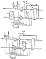
- Fig. 1 is a schematic diagram of a dialysis machine in which the invention according to Swedish Patent Application No. 9702074-7 and the present invention can be practised.
- the dialysis machine provides means for replacing the renal function of a mammal if the renal function is impaired or completely absent, such as end stage renal disease of a human being.
- the blood from a patient is taken out into an extracorporeal circuit 2 including a filter or dialyser 1, including a semipermeable membrane 3.
- the blood passes along one side of the membrane.
- a dialysis fluid is circulated by the dialysis machine 4.
- the dialysis fluid is usually prepared by the machine from one or several concentrates and water to form a dialysis fluid having the desired properties.
- the machine disclosed in Fig. 1 comprises a water inlet 5, two concentrate inlets 6 and 7, and two concentrate metering pumps 8 and 9.
- a first main pump 10 propels the fresh dialysis fluid to the dialysis side of the dialyser into contact with the membrane.
- a second main pump 11 passes the effluent fluid, dialysate, from the dialyser, namely the inlet dialysis fluid and any ultrafiltrate removed from the blood via the filter, further on to an outlet 12 and to the drain.
- a by-pass line 13 is arranged between the first pump 10 and the second pump 11.
- Several valves 14,15,16 are arranged for controlling the flow of dialysis fluid.
- the valves and the pumps are controlled by a computer 17 as schematically shown by several lines in Fig. 1 .
- the dialysis machine is provided with several other means as is conventional. These other means are not disclosed, since they are conventional.
- the first main pump 10 is driven with a speed so that the dialysis fluid delivered to the dialyser is substantially constant, e.g. 500 ml/min.
- the second main pump 11 is driven with a slightly higher speed so that the effluent fluid, called the dialysate, has a flow rate of e.g. 515 ml/min.
- This operation generates a low pressure at the dialysate side of the dialyser, which is suitable for removing 15 ml/min of ultrafiltrate fluid from the blood, i.e. plasma water.
- the dialysis machine is operated so that the treatment prescribed to the patient is fulfilled.
- a urea monitor 18 which measures the urea concentration C d in the effluent dialysate.
- the monitor can be positioned inside the dialysis machine or completely outside the dialysis machine.
- the urea monitor may be of the type disclosed in WO 96/04401 .
- the urea monitor is shown connected to the computer 17 of the dialysis machine. However, the monitor may have a computer of its own.
- the urea monitor or the dialysis machine also includes means for measuring the flow rate of the effluent dialysate, Q d .
- the computer 17 is arranged to provide concentration values c d as well as values of the total mass of urea U removed during the treatment as the integral of Q d ⁇ c d .
- the concentration values are taken continuously so that a concentration curve c d is obtained from the urea monitor as well as a mass curve U.
- Fig. 2 discloses a similar dialysis machine as shown in Fig. 1 .
- the main difference is that the urea monitor 19 is placed between the dialyser 1 and the second main pump 11 and before the outlet of the bypass line.
- Fig. 3 discloses a similar dialysis machine as Fig. 1 , but adapted for hemofiltration or hemodiafiltration. The only difference is that there is included an infusion line 20 including an infusion pump 21.
- the infusion line 20 starts from the outlet of the first main pump 10 and ends at the blood inlet side of the dialyser, for providing an infusion fluid to the blood before the dialyser, called predilution.
- the urea monitor 22 is arranged in the effluent dialysate line after the second pump 11.
- Fig. 4 discloses a similar dialysis machine as Fig. 2 , but adapted for hemofiltration or hemodiafiltration and providing an infusion fluid to the blood after the dialyser, called postdilution.
- the urea monitor 23 is placed before the second main pump 11 and before the outlet of the bypass line.
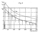
- Fig. 5 discloses a typical urea concentration curve c d obtained from the urea monitor. As appears from the figure, the curve is very irregular and includes several dips. These dips reflect when the dialysis machine is connected for selfcalibration, in which valve 16 is opened and valves 14 and 15 are closed.
- the urea monitor provides a removed urea concentration curve c d as disclosed in Fig. 5 .
- the initial values for example values obtained from 5 minutes to 20 minutes, are used for extrapolating an initial urea concentration c d0 at the start of the dialysis treatment.
- the start of the dialysis treatment is defined as the time when the urea concentration is steadily above a predetermined low concentration value.
- the actual determination of concentration values is initiated five minutes after determining such a steady condition in order to be sure that the treatment is going on and will not be discontinued.
- a disturbance is induced in the fresh dialysis fluid by operating the pumps 8 and 9 controlled by the computer 17.
- the disturbance is generated when the dialysis treatment is in a steady state and may be a change in the ionic content of the dialysis fluid.
- Such a disturbance may be generated by operating both pumps 8 and 9 and increase the speed of these pumps by for example 10% during 60 seconds.
- the resultant disturbance is measured after the dialyser, for example by a conductivity meter, and the measurement result is processed for example as described in EP 658 352 to obtain the effective dialysance K e .
- the measurement is performed as soon as possible and preferably after the initial 20 minutes and without changing any of the parameters influencing on the dialysance of the dialyser, like blood flow rate and dialysate flow rate.
- the concentrations may be sodium concentrations or conductivity of the dialysate.
- Indexes 1 and 2 indicate times before and after the step change.
- the introduced concentration can be measured before the dialyser or be determined by the set values of the concentration pumps.
- the plasma urea concentration can then be corrected for protein content in the blood. This correction is fairly constant for the normal range of protein concentrations, which allows the use of the same correction factor for all patients, although the best accuracy is achieved if the true protein content is used.
- the urea monitor includes a conductivity meter, which may be used for measuring the conductivity after the dialyser, so there need not be any separate conductivity meter after the dialyser for the measurement according to the present invention.
- the set values of the disturbance can be used.
- the disturbance may be induced in different manners.
- a pump 24 is connected to the inlet of the dialyser downstream of valve 14.
- the pump is also connected to a small bag 25 containing a predetermined quantity of urea dissolved in water or dialysis fluid (or an isotonic solution) and having a predetermined concentration.
- the disturbance induced by this introduction of the known amount of urea in the dialysis circuit is measured by the urea monitor downstream of the dialyser and the result is evaluated by the computer 17.
- the mass of urea reaching the urea monitor can be calculated by multiplication with the flow rate Q d .
- the difference from the amount introduced, which is known, must have passed through the membrane of the dialyser into the blood of the patient.
- the bag 25 may include sodium ions instead of urea and the conductivity meter of the urea monitor may be used for measuring the increased conductivity due to the introduction of extra sodium ions. It is known that the clearance for sodium ions is approximately equal to the clearance of urea. Other types of ions or substances can also be used as well as decreases instead of increases of the concentration or conductivity of the fresh dialysis solution.
- the integral S in times the dialysis fluid flow equals the amount of material added to the solution.
- the material can be added in any way that enables the measurement at the outlet side of the dialyser, i.e. the disturbance need not be rectangular, but can have any shape.
- the introduction flow rate of the material in the dialysate flow is of no importance as soon as it is of such a flow rate that the resultant disturbance is not too small to be measured and not to large to be outside the measuring capability of the measurement instrument at the outlet side of the dialyser.
- the disturbance must also be compatible with the body.
- the added material can be dissolved in water, whereby the dilution effect should be considered when introducing the material in the circuit.
- Another approach would be to dissolve the material in normal dialysis fluid, for example dissolve a known amount of urea in a known amount of dialysis fluid. This dissolution can be performed in advance, so that the material is delivered in bag 25 to be connected to the dialysis circuit.
- the material can be delivered in powder form, for example a known amount of urea in powder form in a bag 25.
- the bag is connected to the dialysis machine, and the pump 24 is operated to introduce a known amount of dialysis fluid in the bag to dissolve the amount of material. After dissolution, the pump 24 is reversed and the material in the bag is introduced into the circuit.
- the main pump 16 can be operated so that the total amount of fluid entering the dialyser is constant, i.e. the flow rate of pump 16 and pump 24 is constant. For example, if pump 24 is operated at a speed of 50 ml/min, pump 16 is reduced to 450 ml/min during the introduction period and returned to 500 ml/min after the introduction of the substance.
- the disturbance may be introduced at the other side of the membrane as suggested in Fig. 2 by pump 26 and bag 27.
- pump 26 and bag 27 an introduction of urea of a known concentration and/or amount will result in an increase of the urea concentration in the dialysate reaching the urea monitor.
- This disturbance can be integrated and processed for obtaining the clearance of the dialyser.
- the added material can be fresh dialysis fluid obtained from the dialysis machine, but of a higher (or lower) ionic strength or osmolarity, whereby the conductivity is measured.
- fresh dialysis fluid can be added, which comprises no urea, and the resulting diluting effect on urea in blood can be determined on the dialysate side by the urea monitor.
- the added material such as urea can be diluted in water or dialysis fluid as indicated above.
- the material can be delivered in powder form in a bag 27 and dissolved in blood by reversing pump 26 and introducing blood in the bag for dissolution of the material and then operating the pump 26 in the normal direction for introducing the material in the circuit.
- the time of the measurement may be shortened by using the exponential behaviour of the disturbance for calculating the result as stated in EP 658 352 .
- the time may be shortened in the same way by estimating the error when the measurement is terminated in advance.
Claims (3)
- Vorrichtung zum Berechnen der Konzentration einer ersten Substanz im Blut eines Säugers, mit:einem Mittel, um das Blut durch einen Dialysator zu leiten, der eine semipermeable Membran umfasst, und einem Mittel, um ein Dialy-sefluid an der anderen Seite der Membran zu leiten, wodurch ein Dialysat erzeugt wird;einem Mittel zum Messen der Konzentration (cd) der ersten Substanz in dem von dem Dialysator abgegebenen Dialysat;gekennzeichnet durch:ein Mittel zum Einführen einer Störung in dem Dialysator in der Beschaffenheit einer Änderung der Konzentration einer zweiten Substanz, die nicht gleich der ersten Substanz ist, in dem in den Dialysator eingeführten Dialysefluid;ein Mittel zum Messen der resultierenden Änderung der Konzentration der zweiten Substanz in dem den Dialysator verlassenen Dialysat;ein Mittel zum Berechnen der effektiven Dialysance (Ke) des Dialysators auf Grundlage der Störung;ein Mittel zum Erhalten des Dialysatdurchsatzes (Qd); undein Mittel zum Berechnen der Konzentration (cpw) der ersten Substanz im Blut mit der Formel:

- Vorrichtung nach Anspruch 1,
gekennzeichnet durch:ein Mittel zum Messen der Konzentration (cd) der ersten Substanz in dem Dialysat, um eine Kurve der Konzentration gegenüber der Zeit zu erhalten;ein Mittel zum Berechnen der anfänglichen Masse (mo) der ersten Substanz in dem Körper;ein Mittel zum Berechnen der anfänglichen Konzentration (cpwo) der ersten Substanz in dem Körper durch Extrapolation auf eine Anfangszeit; undein Mittel zum Berechnen des Verteilungsvolumens (V) der ersten Substanz in dem Körper des Säugers gemäß der Formel:
- Vorrichtung nach einem der Ansprüche 1 oder 2,
dadurch gekennzeichnet, dass die erste Substanz Harnstoff ist und die zweite Substanz Natriumionen, andere Typen von Ionen oder Substanzen sind, die die Leitfähigkeit ändern.
Priority Applications (1)
| Application Number | Priority Date | Filing Date | Title |
|---|---|---|---|
| DE69838400.8T DE69838400T3 (de) | 1997-12-09 | 1998-12-02 | Vorrichtung zur berechnung der dialyseeffizienz |
Applications Claiming Priority (5)
| Application Number | Priority Date | Filing Date | Title |
|---|---|---|---|
| FR9715818A FR2771931B1 (fr) | 1997-12-09 | 1997-12-09 | Procede de determination d'un parametre significatif du progres d'un traitement extracorporel de sang |
| FR9715818 | 1997-12-09 | ||
| SE9801963A SE513034C2 (sv) | 1997-06-02 | 1998-06-02 | Metod och anordning för beräkning av dialyseffektivitet |
| SE9801963 | 1998-06-02 | ||
| PCT/SE1998/002212 WO1999029355A1 (en) | 1997-12-09 | 1998-12-02 | Method and device for calculating dialysis efficiency |
Publications (3)
| Publication Number | Publication Date |
|---|---|
| EP1037681A1 EP1037681A1 (de) | 2000-09-27 |
| EP1037681B1 EP1037681B1 (de) | 2007-09-05 |
| EP1037681B2 true EP1037681B2 (de) | 2014-05-28 |
Family
ID=26233990
Family Applications (1)
| Application Number | Title | Priority Date | Filing Date |
|---|---|---|---|
| EP98962767.4A Expired - Lifetime EP1037681B2 (de) | 1997-12-09 | 1998-12-02 | Vorrichtung zur berechnung der dialyseeffizienz |
Country Status (10)
| Country | Link |
|---|---|
| US (1) | US6861266B1 (de) |
| EP (1) | EP1037681B2 (de) |
| JP (1) | JP4159250B2 (de) |
| AT (1) | ATE372139T1 (de) |
| AU (1) | AU743208B2 (de) |
| CA (1) | CA2313209C (de) |
| DE (1) | DE69838400T3 (de) |
| ES (1) | ES2293697T5 (de) |
| SE (1) | SE513034C2 (de) |
| WO (1) | WO1999029355A1 (de) |
Families Citing this family (50)
| Publication number | Priority date | Publication date | Assignee | Title |
|---|---|---|---|---|
| US6726647B1 (en) | 1998-10-23 | 2004-04-27 | Gambro Ab | Method and device for measuring access flow |
| EP2198900B1 (de) | 1998-10-23 | 2016-02-10 | Gambro Lundia AB | Verfahren und Vorrichtung zum Erkennen einer Rezirkulation |
| US7077819B1 (en) | 1998-12-24 | 2006-07-18 | Fresenius Medical Care Deutschland Gmbh | Method for determining the distribution volume of a blood component during an extracorporeal blood treatment and device for carrying out the method |
| US7488447B2 (en) | 2002-10-30 | 2009-02-10 | Gambro Lundia Ab | Method and an apparatus for determining the efficiency of dialysis |
| US7744553B2 (en) | 2003-12-16 | 2010-06-29 | Baxter International Inc. | Medical fluid therapy flow control systems and methods |
| DE102005001051B4 (de) * | 2005-01-07 | 2007-10-31 | Fresenius Medical Care Deutschland Gmbh | Vorrichtung und Verfahren zur Erkennung von Komplikationen während einer extrakorporalen Blutbehandlung |
| US7219021B2 (en) * | 2005-09-13 | 2007-05-15 | Honeywell International Inc. | Multiple wireless sensors for dialysis application |
| US7815809B2 (en) * | 2005-12-13 | 2010-10-19 | Gambro Lundia Ab | Method for conductivity calculation in a treatment fluid upstream and downstream a filtration unit in apparatuses for the blood treatment |
| WO2008046630A1 (en) | 2006-10-19 | 2008-04-24 | Joanneum Research Forschungsgesellschaft Mbh | Devices for and methods of monitoring a parameter of a fluidic sample by microdialysis |
| US20110073543A1 (en) * | 2009-09-28 | 2011-03-31 | Anticline Disposal, Llc | System and method for using urea as a nitrogen source in a bioreactor |
| US8945936B2 (en) * | 2011-04-06 | 2015-02-03 | Fresenius Medical Care Holdings, Inc. | Measuring chemical properties of a sample fluid in dialysis systems |
| EP2747808B1 (de) | 2011-08-22 | 2016-11-30 | Medtronic Inc. | Zweiflutige sorptionsmittelkartusche |
| WO2013103906A1 (en) | 2012-01-04 | 2013-07-11 | Medtronic, Inc. | Multi-staged filtration system for blood fluid removal |
| US9713666B2 (en) | 2013-01-09 | 2017-07-25 | Medtronic, Inc. | Recirculating dialysate fluid circuit for blood measurement |
| US9707328B2 (en) | 2013-01-09 | 2017-07-18 | Medtronic, Inc. | Sorbent cartridge to measure solute concentrations |
| US11154648B2 (en) | 2013-01-09 | 2021-10-26 | Medtronic, Inc. | Fluid circuits for sorbent cartridge with sensors |
| US11565029B2 (en) | 2013-01-09 | 2023-01-31 | Medtronic, Inc. | Sorbent cartridge with electrodes |
| US10010663B2 (en) | 2013-02-01 | 2018-07-03 | Medtronic, Inc. | Fluid circuit for delivery of renal replacement therapies |
| US10850016B2 (en) | 2013-02-01 | 2020-12-01 | Medtronic, Inc. | Modular fluid therapy system having jumpered flow paths and systems and methods for cleaning and disinfection |
| US9623164B2 (en) | 2013-02-01 | 2017-04-18 | Medtronic, Inc. | Systems and methods for multifunctional volumetric fluid control |
| US9144640B2 (en) | 2013-02-02 | 2015-09-29 | Medtronic, Inc. | Sorbent cartridge configurations for improved dialysate regeneration |
| US9827361B2 (en) | 2013-02-02 | 2017-11-28 | Medtronic, Inc. | pH buffer measurement system for hemodialysis systems |
| DE102013104501A1 (de) * | 2013-05-02 | 2014-11-06 | B. Braun Avitum Ag | Vorrichtung zur extrakorporalen Blutbehandlung |
| US10004839B2 (en) | 2013-11-26 | 2018-06-26 | Medtronic, Inc. | Multi-use sorbent cartridge |
| US10052612B2 (en) | 2013-11-26 | 2018-08-21 | Medtronic, Inc. | Zirconium phosphate recharging method and apparatus |
| US9884145B2 (en) | 2013-11-26 | 2018-02-06 | Medtronic, Inc. | Parallel modules for in-line recharging of sorbents using alternate duty cycles |
| US9943780B2 (en) | 2013-11-26 | 2018-04-17 | Medtronic, Inc. | Module for in-line recharging of sorbent materials with optional bypass |
| US10537875B2 (en) | 2013-11-26 | 2020-01-21 | Medtronic, Inc. | Precision recharging of sorbent materials using patient and session data |
| US9895477B2 (en) | 2013-11-26 | 2018-02-20 | Medtronic, Inc. | Detachable module for recharging sorbent materials with optional bypass |
| DE102014104768A1 (de) | 2014-04-03 | 2015-10-29 | B. Braun Avitum Ag | Vorrichtung und Verfahren zum Bestimmen eines Verteilungsvolumens bei einem Dialysepatienten |
| WO2015199766A1 (en) | 2014-06-24 | 2015-12-30 | Medtronic, Inc. | Modular dialysate regeneration assembly |
| WO2015199760A1 (en) | 2014-06-24 | 2015-12-30 | Medtronic, Inc. | Replenisihing urease in dialysis systems using a urease introducer |
| WO2015199761A1 (en) | 2014-06-24 | 2015-12-30 | Medtronic, Inc. | Sorbent pouch |
| EP3160534A4 (de) | 2014-06-24 | 2018-03-07 | Medtronic Inc. | Gestapelte sorptionsmittelanordnung |
| US10272363B2 (en) | 2014-06-24 | 2019-04-30 | Medtronic, Inc. | Urease introduction system for replenishing urease in a sorbent cartridge |
| EP3160529B1 (de) | 2014-06-24 | 2019-11-13 | Medtronic Inc. | Ureasenachfüllung in dialysesystemen mit ureasebeutel |
| DE102014012423A1 (de) * | 2014-08-20 | 2016-02-25 | Fresenius Medical Care Deutschland Gmbh | Dialysemaschine mit der Fähigkeit zur Bestimmung einer prädialytischen Eigenschaft im Blut eines Dialysepatienten |
| US10098993B2 (en) | 2014-12-10 | 2018-10-16 | Medtronic, Inc. | Sensing and storage system for fluid balance |
| US10874787B2 (en) | 2014-12-10 | 2020-12-29 | Medtronic, Inc. | Degassing system for dialysis |
| US9713665B2 (en) | 2014-12-10 | 2017-07-25 | Medtronic, Inc. | Degassing system for dialysis |
| DE102015103484A1 (de) * | 2015-03-10 | 2016-09-15 | Endress + Hauser Conducta Gesellschaft für Mess- und Regeltechnik mbH + Co. KG | In-Line-Messeinrichtung |
| US10981148B2 (en) | 2016-11-29 | 2021-04-20 | Medtronic, Inc. | Zirconium oxide module conditioning |
| US11167070B2 (en) | 2017-01-30 | 2021-11-09 | Medtronic, Inc. | Ganged modular recharging system |
| US10960381B2 (en) | 2017-06-15 | 2021-03-30 | Medtronic, Inc. | Zirconium phosphate disinfection recharging and conditioning |
| US11860075B2 (en) * | 2017-11-28 | 2024-01-02 | Organo Corporation | Analyzing method and analyzing apparatus for urea |
| US11278654B2 (en) | 2017-12-07 | 2022-03-22 | Medtronic, Inc. | Pneumatic manifold for a dialysis system |
| EP3738624B1 (de) * | 2018-01-10 | 2022-09-14 | Nipro Corporation | Vorrichtung zur berechnung der menge an extrazellulärer flüssigkeit und verfahren zur berechnung der menge an extrazellulärer flüssigkeit |
| US11033667B2 (en) | 2018-02-02 | 2021-06-15 | Medtronic, Inc. | Sorbent manifold for a dialysis system |
| US11110215B2 (en) | 2018-02-23 | 2021-09-07 | Medtronic, Inc. | Degasser and vent manifolds for dialysis |
| US11213616B2 (en) | 2018-08-24 | 2022-01-04 | Medtronic, Inc. | Recharge solution for zirconium phosphate |
Citations (3)
| Publication number | Priority date | Publication date | Assignee | Title |
|---|---|---|---|---|
| US4244787A (en) † | 1979-06-11 | 1981-01-13 | The United States Of America As Represented By The Secretary Of The Department Of Health, Education & Welfare | Apparatus and method for determining serum concentrates of metabolites by monitoring dialysate fluid |
| EP0428927A1 (de) † | 1989-11-21 | 1991-05-29 | Fresenius AG | Verfahren zur Bestimmung von Hämodialyse-Parametern während der Hämodialyse |
| EP0911043A1 (de) † | 1997-10-27 | 1999-04-28 | Polaschegg, Hans-Dietrich, Dr.techn. | Verfahren zur Messung von Leistungsparametern von Stoff- und Energieaustausch Modulen |
Family Cites Families (11)
| Publication number | Priority date | Publication date | Assignee | Title |
|---|---|---|---|---|
| SE465404B (sv) * | 1988-03-03 | 1991-09-09 | Gambro Ab | Dialyssystem |
| FR2693110B1 (fr) * | 1992-07-06 | 1994-08-19 | Hospal Ind | Procédé de vérification du fonctionnement de capteurs situés sur un circuit de liquide de dialyse et dispositif en faisant application. |
| US5644240A (en) * | 1992-09-30 | 1997-07-01 | Cobe Laboratories, Inc. | Differential conductivity hemodynamic monitor |
| FR2713937B1 (fr) * | 1993-12-17 | 1996-05-31 | Hospal Ind | Procédé de détermination d'un paramètre significatif du progrès d'un traitement extracorporel de sang. |
| US5507723A (en) | 1994-05-24 | 1996-04-16 | Baxter International, Inc. | Method and system for optimizing dialysis clearance |
| DE69530986T2 (de) | 1994-07-29 | 2004-05-19 | Gambro Lundia Ab | Verfahren und vorrichtung zur messung der konzentration einer substanz in einer lösung |
| DE19746367C2 (de) * | 1996-11-30 | 1999-08-26 | Fresenius Medical Care De Gmbh | Verfahren zur in-vivo-Bestimmung von Parametern der Hämodialyse und Vorrichtung zur Durchführung des Verfahrens |
| FR2771931B1 (fr) * | 1997-12-09 | 2000-01-07 | Hospal Ind | Procede de determination d'un parametre significatif du progres d'un traitement extracorporel de sang |
| SE9702074D0 (sv) | 1997-06-02 | 1997-06-02 | Gambro Ab | Method and device for calculating dialysis efficiency |
| EP1927370B1 (de) * | 1997-08-13 | 2013-10-02 | Fresenius Medical Care Deutschland GmbH | Verfahren zur Bestimmung von Parametern der Hämodialyse und Blutbehandlungsvorrichtung mit einer Einrichtung zur Bestimmung von Parametern der Hämodialyse |
| FR2767478B1 (fr) * | 1997-08-21 | 1999-10-01 | Hospal Ind | Dispositif et procede pour regler la concentration du sodium dans un liquide de dialyse en vue d'une prescription |
-
1998
- 1998-06-02 SE SE9801963A patent/SE513034C2/sv not_active IP Right Cessation
- 1998-12-02 US US09/581,352 patent/US6861266B1/en not_active Expired - Lifetime
- 1998-12-02 WO PCT/SE1998/002212 patent/WO1999029355A1/en active IP Right Grant
- 1998-12-02 CA CA002313209A patent/CA2313209C/en not_active Expired - Fee Related
- 1998-12-02 JP JP2000524024A patent/JP4159250B2/ja not_active Expired - Fee Related
- 1998-12-02 ES ES98962767.4T patent/ES2293697T5/es not_active Expired - Lifetime
- 1998-12-02 DE DE69838400.8T patent/DE69838400T3/de not_active Expired - Lifetime
- 1998-12-02 AU AU17928/99A patent/AU743208B2/en not_active Ceased
- 1998-12-02 EP EP98962767.4A patent/EP1037681B2/de not_active Expired - Lifetime
- 1998-12-02 AT AT98962767T patent/ATE372139T1/de not_active IP Right Cessation
Patent Citations (3)
| Publication number | Priority date | Publication date | Assignee | Title |
|---|---|---|---|---|
| US4244787A (en) † | 1979-06-11 | 1981-01-13 | The United States Of America As Represented By The Secretary Of The Department Of Health, Education & Welfare | Apparatus and method for determining serum concentrates of metabolites by monitoring dialysate fluid |
| EP0428927A1 (de) † | 1989-11-21 | 1991-05-29 | Fresenius AG | Verfahren zur Bestimmung von Hämodialyse-Parametern während der Hämodialyse |
| EP0911043A1 (de) † | 1997-10-27 | 1999-04-28 | Polaschegg, Hans-Dietrich, Dr.techn. | Verfahren zur Messung von Leistungsparametern von Stoff- und Energieaustausch Modulen |
Also Published As
| Publication number | Publication date |
|---|---|
| AU1792899A (en) | 1999-06-28 |
| CA2313209A1 (en) | 1999-06-17 |
| ES2293697T5 (es) | 2014-08-14 |
| DE69838400T2 (de) | 2009-01-22 |
| SE9801963L (sv) | 1998-12-03 |
| ATE372139T1 (de) | 2007-09-15 |
| EP1037681A1 (de) | 2000-09-27 |
| EP1037681B1 (de) | 2007-09-05 |
| ES2293697T3 (es) | 2008-03-16 |
| JP2003523776A (ja) | 2003-08-12 |
| WO1999029355A1 (en) | 1999-06-17 |
| JP4159250B2 (ja) | 2008-10-01 |
| US6861266B1 (en) | 2005-03-01 |
| SE9801963D0 (sv) | 1998-06-02 |
| SE513034C2 (sv) | 2000-06-19 |
| AU743208B2 (en) | 2002-01-24 |
| DE69838400T3 (de) | 2014-10-02 |
| CA2313209C (en) | 2006-09-12 |
| DE69838400D1 (de) | 2007-10-18 |
Similar Documents
| Publication | Publication Date | Title |
|---|---|---|
| EP1037681B2 (de) | Vorrichtung zur berechnung der dialyseeffizienz | |
| JP4148536B2 (ja) | 透析の効率を計算する装置 | |
| EP1582226B2 (de) | Vorrichtung zur Bestimmung von Hämodialyseparametern | |
| US7563240B2 (en) | Haemodialysis device | |
| JP4077034B2 (ja) | 平衡試料および2プール動力学に関する相互区画移動係数を得るための自動化法および装置 | |
| JP3547436B2 (ja) | 血液透析機器のための血液透析モニタリングシステム | |
| US6939471B2 (en) | Method for determining a treatment parameter on a haemofiltration device, and haemofiltration device for applying the method | |
| JPH03173569A (ja) | 血液透析パラメーターの体内測定法 | |
| JP4219094B2 (ja) | ダイアリサンスを決定する方法および該方法のための装置 | |
| JP4408644B2 (ja) | 血液ろ過装置 |
Legal Events
| Date | Code | Title | Description |
|---|---|---|---|
| PUAI | Public reference made under article 153(3) epc to a published international application that has entered the european phase |
Free format text: ORIGINAL CODE: 0009012 |
|
| 17P | Request for examination filed |
Effective date: 20000710 |
|
| AK | Designated contracting states |
Kind code of ref document: A1 Designated state(s): AT BE CH DE DK ES FI FR GB GR IE IT LI LU NL PT SE |
|
| 17Q | First examination report despatched |
Effective date: 20041102 |
|
| RAP1 | Party data changed (applicant data changed or rights of an application transferred) |
Owner name: GAMBRO AKTIEBOLAG |
|
| GRAP | Despatch of communication of intention to grant a patent |
Free format text: ORIGINAL CODE: EPIDOSNIGR1 |
|
| RTI1 | Title (correction) |
Free format text: DEVICE FOR CALCULATING DIALYSIS EFFICIENCY |
|
| GRAS | Grant fee paid |
Free format text: ORIGINAL CODE: EPIDOSNIGR3 |
|
| REG | Reference to a national code |
Ref country code: HK Ref legal event code: WD Ref document number: 1031345 Country of ref document: HK |
|
| GRAA | (expected) grant |
Free format text: ORIGINAL CODE: 0009210 |
|
| AK | Designated contracting states |
Kind code of ref document: B1 Designated state(s): AT BE CH DE DK ES FI FR GB GR IE IT LI LU NL PT SE |
|
| REG | Reference to a national code |
Ref country code: GB Ref legal event code: FG4D |
|
| REG | Reference to a national code |
Ref country code: CH Ref legal event code: EP |
|
| RIN2 | Information on inventor provided after grant (corrected) |
Inventor name: STERNBY, JAN |
|
| REF | Corresponds to: |
Ref document number: 69838400 Country of ref document: DE Date of ref document: 20071018 Kind code of ref document: P |
|
| REG | Reference to a national code |
Ref country code: IE Ref legal event code: FG4D |
|
| PG25 | Lapsed in a contracting state [announced via postgrant information from national office to epo] |
Ref country code: FI Free format text: LAPSE BECAUSE OF FAILURE TO SUBMIT A TRANSLATION OF THE DESCRIPTION OR TO PAY THE FEE WITHIN THE PRESCRIBED TIME-LIMIT Effective date: 20070905 |
|
| PG25 | Lapsed in a contracting state [announced via postgrant information from national office to epo] |
Ref country code: CH Free format text: LAPSE BECAUSE OF FAILURE TO SUBMIT A TRANSLATION OF THE DESCRIPTION OR TO PAY THE FEE WITHIN THE PRESCRIBED TIME-LIMIT Effective date: 20070905 Ref country code: LI Free format text: LAPSE BECAUSE OF FAILURE TO SUBMIT A TRANSLATION OF THE DESCRIPTION OR TO PAY THE FEE WITHIN THE PRESCRIBED TIME-LIMIT Effective date: 20070905 Ref country code: AT Free format text: LAPSE BECAUSE OF FAILURE TO SUBMIT A TRANSLATION OF THE DESCRIPTION OR TO PAY THE FEE WITHIN THE PRESCRIBED TIME-LIMIT Effective date: 20070905 |
|
| NLV1 | Nl: lapsed or annulled due to failure to fulfill the requirements of art. 29p and 29m of the patents act | ||
| REG | Reference to a national code |
Ref country code: ES Ref legal event code: FG2A Ref document number: 2293697 Country of ref document: ES Kind code of ref document: T3 |
|
| REG | Reference to a national code |
Ref country code: GB Ref legal event code: 732E |
|
| PG25 | Lapsed in a contracting state [announced via postgrant information from national office to epo] |
Ref country code: BE Free format text: LAPSE BECAUSE OF FAILURE TO SUBMIT A TRANSLATION OF THE DESCRIPTION OR TO PAY THE FEE WITHIN THE PRESCRIBED TIME-LIMIT Effective date: 20070905 |
|
| REG | Reference to a national code |
Ref country code: CH Ref legal event code: PL |
|
| PG25 | Lapsed in a contracting state [announced via postgrant information from national office to epo] |
Ref country code: NL Free format text: LAPSE BECAUSE OF FAILURE TO SUBMIT A TRANSLATION OF THE DESCRIPTION OR TO PAY THE FEE WITHIN THE PRESCRIBED TIME-LIMIT Effective date: 20070905 Ref country code: GR Free format text: LAPSE BECAUSE OF FAILURE TO SUBMIT A TRANSLATION OF THE DESCRIPTION OR TO PAY THE FEE WITHIN THE PRESCRIBED TIME-LIMIT Effective date: 20071206 |
|
| EN | Fr: translation not filed | ||
| PG25 | Lapsed in a contracting state [announced via postgrant information from national office to epo] |
Ref country code: PT Free format text: LAPSE BECAUSE OF FAILURE TO SUBMIT A TRANSLATION OF THE DESCRIPTION OR TO PAY THE FEE WITHIN THE PRESCRIBED TIME-LIMIT Effective date: 20080206 |
|
| PLBI | Opposition filed |
Free format text: ORIGINAL CODE: 0009260 |
|
| PG25 | Lapsed in a contracting state [announced via postgrant information from national office to epo] |
Ref country code: SE Free format text: LAPSE BECAUSE OF FAILURE TO SUBMIT A TRANSLATION OF THE DESCRIPTION OR TO PAY THE FEE WITHIN THE PRESCRIBED TIME-LIMIT Effective date: 20071205 |
|
| REG | Reference to a national code |
Ref country code: ES Ref legal event code: PC2A |
|
| PLAX | Notice of opposition and request to file observation + time limit sent |
Free format text: ORIGINAL CODE: EPIDOSNOBS2 |
|
| ET | Fr: translation filed | ||
| REG | Reference to a national code |
Ref country code: FR Ref legal event code: EERR Free format text: CORRECTION DE BOPI 08/18 - BREVETS EUROPEENS DONT LA TRADUCTION N A PAS ETE REMISE A L INPI. IL Y A LIEU DE SUPPRIMER : LA MENTION DE LA NON-REMISE. LA REMISE DE LA TRADUCTION EST PUBLIEE DANS LE PRESENT BOPI. |
|
| 26 | Opposition filed |
Opponent name: FRESENIUS MEDICAL CARE DEUTSCHLAND GMBH Effective date: 20080603 |
|
| PG25 | Lapsed in a contracting state [announced via postgrant information from national office to epo] |
Ref country code: DK Free format text: LAPSE BECAUSE OF FAILURE TO SUBMIT A TRANSLATION OF THE DESCRIPTION OR TO PAY THE FEE WITHIN THE PRESCRIBED TIME-LIMIT Effective date: 20070905 |
|
| REG | Reference to a national code |
Ref country code: FR Ref legal event code: TP |
|
| PG25 | Lapsed in a contracting state [announced via postgrant information from national office to epo] |
Ref country code: FR Free format text: LAPSE BECAUSE OF FAILURE TO SUBMIT A TRANSLATION OF THE DESCRIPTION OR TO PAY THE FEE WITHIN THE PRESCRIBED TIME-LIMIT Effective date: 20080502 |
|
| PG25 | Lapsed in a contracting state [announced via postgrant information from national office to epo] |
Ref country code: IE Free format text: LAPSE BECAUSE OF NON-PAYMENT OF DUE FEES Effective date: 20071203 |
|
| PLAF | Information modified related to communication of a notice of opposition and request to file observations + time limit |
Free format text: ORIGINAL CODE: EPIDOSCOBS2 |
|
| PLBB | Reply of patent proprietor to notice(s) of opposition received |
Free format text: ORIGINAL CODE: EPIDOSNOBS3 |
|
| REG | Reference to a national code |
Ref country code: GB Ref legal event code: 732E Free format text: REGISTERED BETWEEN 20090528 AND 20090603 |
|
| REG | Reference to a national code |
Ref country code: FR Ref legal event code: GC |
|
| PG25 | Lapsed in a contracting state [announced via postgrant information from national office to epo] |
Ref country code: LU Free format text: LAPSE BECAUSE OF NON-PAYMENT OF DUE FEES Effective date: 20071202 |
|
| REG | Reference to a national code |
Ref country code: FR Ref legal event code: RG Effective date: 20120215 |
|
| APBM | Appeal reference recorded |
Free format text: ORIGINAL CODE: EPIDOSNREFNO |
|
| APBP | Date of receipt of notice of appeal recorded |
Free format text: ORIGINAL CODE: EPIDOSNNOA2O |
|
| APAH | Appeal reference modified |
Free format text: ORIGINAL CODE: EPIDOSCREFNO |
|
| APBU | Appeal procedure closed |
Free format text: ORIGINAL CODE: EPIDOSNNOA9O |
|
| PUAH | Patent maintained in amended form |
Free format text: ORIGINAL CODE: 0009272 |
|
| STAA | Information on the status of an ep patent application or granted ep patent |
Free format text: STATUS: PATENT MAINTAINED AS AMENDED |
|
| 27A | Patent maintained in amended form |
Effective date: 20140528 |
|
| AK | Designated contracting states |
Kind code of ref document: B2 Designated state(s): AT BE CH DE DK ES FI FR GB GR IE IT LI LU NL PT SE |
|
| REG | Reference to a national code |
Ref country code: DE Ref legal event code: R102 Ref document number: 69838400 Country of ref document: DE |
|
| REG | Reference to a national code |
Ref country code: DE Ref legal event code: R102 Ref document number: 69838400 Country of ref document: DE Effective date: 20140528 |
|
| REG | Reference to a national code |
Ref country code: ES Ref legal event code: DC2A Ref document number: 2293697 Country of ref document: ES Kind code of ref document: T5 Effective date: 20140814 |
|
| PGFP | Annual fee paid to national office [announced via postgrant information from national office to epo] |
Ref country code: GB Payment date: 20141124 Year of fee payment: 17 Ref country code: ES Payment date: 20141216 Year of fee payment: 17 |
|
| PGFP | Annual fee paid to national office [announced via postgrant information from national office to epo] |
Ref country code: FR Payment date: 20141124 Year of fee payment: 17 |
|
| PGFP | Annual fee paid to national office [announced via postgrant information from national office to epo] |
Ref country code: IT Payment date: 20141216 Year of fee payment: 17 |
|
| PGFP | Annual fee paid to national office [announced via postgrant information from national office to epo] |
Ref country code: DE Payment date: 20141222 Year of fee payment: 17 |
|
| REG | Reference to a national code |
Ref country code: DE Ref legal event code: R119 Ref document number: 69838400 Country of ref document: DE |
|
| GBPC | Gb: european patent ceased through non-payment of renewal fee |
Effective date: 20151202 |
|
| REG | Reference to a national code |
Ref country code: FR Ref legal event code: ST Effective date: 20160831 |
|
| PG25 | Lapsed in a contracting state [announced via postgrant information from national office to epo] |
Ref country code: DE Free format text: LAPSE BECAUSE OF NON-PAYMENT OF DUE FEES Effective date: 20160701 Ref country code: GB Free format text: LAPSE BECAUSE OF NON-PAYMENT OF DUE FEES Effective date: 20151202 |
|
| PG25 | Lapsed in a contracting state [announced via postgrant information from national office to epo] |
Ref country code: FR Free format text: LAPSE BECAUSE OF NON-PAYMENT OF DUE FEES Effective date: 20151231 |
|
| PG25 | Lapsed in a contracting state [announced via postgrant information from national office to epo] |
Ref country code: IT Free format text: LAPSE BECAUSE OF NON-PAYMENT OF DUE FEES Effective date: 20151202 |
|
| REG | Reference to a national code |
Ref country code: ES Ref legal event code: FD2A Effective date: 20170127 |
|
| PG25 | Lapsed in a contracting state [announced via postgrant information from national office to epo] |
Ref country code: ES Free format text: LAPSE BECAUSE OF NON-PAYMENT OF DUE FEES Effective date: 20151203 |