EP1037020A2 - Détection optique de déplacements - Google Patents
Détection optique de déplacements Download PDFInfo
- Publication number
- EP1037020A2 EP1037020A2 EP00301645A EP00301645A EP1037020A2 EP 1037020 A2 EP1037020 A2 EP 1037020A2 EP 00301645 A EP00301645 A EP 00301645A EP 00301645 A EP00301645 A EP 00301645A EP 1037020 A2 EP1037020 A2 EP 1037020A2
- Authority
- EP
- European Patent Office
- Prior art keywords
- target
- data frames
- encoder
- pattern
- processor
- Prior art date
- Legal status (The legal status is an assumption and is not a legal conclusion. Google has not performed a legal analysis and makes no representation as to the accuracy of the status listed.)
- Granted
Links
- 230000003287 optical effect Effects 0.000 title claims abstract description 27
- 238000001514 detection method Methods 0.000 title description 3
- 238000000034 method Methods 0.000 claims abstract description 18
- 238000006073 displacement reaction Methods 0.000 claims abstract description 10
- 238000009304 pastoral farming Methods 0.000 claims description 11
- 238000005259 measurement Methods 0.000 claims description 10
- 230000002123 temporal effect Effects 0.000 claims description 8
- 238000003384 imaging method Methods 0.000 claims description 6
- 230000008569 process Effects 0.000 abstract description 3
- 230000009897 systematic effect Effects 0.000 abstract description 2
- 238000005286 illumination Methods 0.000 description 11
- 238000012546 transfer Methods 0.000 description 7
- 230000008859 change Effects 0.000 description 6
- 238000004519 manufacturing process Methods 0.000 description 5
- 239000000463 material Substances 0.000 description 5
- 239000000758 substrate Substances 0.000 description 4
- 230000001427 coherent effect Effects 0.000 description 3
- 230000007547 defect Effects 0.000 description 2
- 238000010586 diagram Methods 0.000 description 2
- 239000000835 fiber Substances 0.000 description 2
- 230000003252 repetitive effect Effects 0.000 description 2
- 230000001960 triggered effect Effects 0.000 description 2
- 238000010521 absorption reaction Methods 0.000 description 1
- 230000009471 action Effects 0.000 description 1
- 238000013459 approach Methods 0.000 description 1
- 230000000295 complement effect Effects 0.000 description 1
- 238000011109 contamination Methods 0.000 description 1
- 230000002596 correlated effect Effects 0.000 description 1
- 230000000875 corresponding effect Effects 0.000 description 1
- 230000001419 dependent effect Effects 0.000 description 1
- 238000013461 design Methods 0.000 description 1
- 238000009826 distribution Methods 0.000 description 1
- 238000001125 extrusion Methods 0.000 description 1
- 239000004744 fabric Substances 0.000 description 1
- 230000006870 function Effects 0.000 description 1
- 238000003754 machining Methods 0.000 description 1
- 230000007246 mechanism Effects 0.000 description 1
- 239000002245 particle Substances 0.000 description 1
- 230000002093 peripheral effect Effects 0.000 description 1
- 239000013074 reference sample Substances 0.000 description 1
- 230000004044 response Effects 0.000 description 1
- 230000000630 rising effect Effects 0.000 description 1
- 239000000523 sample Substances 0.000 description 1
- 238000005070 sampling Methods 0.000 description 1
- 230000003595 spectral effect Effects 0.000 description 1
- 230000007704 transition Effects 0.000 description 1
Images


Classifications
-
- G—PHYSICS
- G01—MEASURING; TESTING
- G01D—MEASURING NOT SPECIALLY ADAPTED FOR A SPECIFIC VARIABLE; ARRANGEMENTS FOR MEASURING TWO OR MORE VARIABLES NOT COVERED IN A SINGLE OTHER SUBCLASS; TARIFF METERING APPARATUS; MEASURING OR TESTING NOT OTHERWISE PROVIDED FOR
- G01D5/00—Mechanical means for transferring the output of a sensing member; Means for converting the output of a sensing member to another variable where the form or nature of the sensing member does not constrain the means for converting; Transducers not specially adapted for a specific variable
- G01D5/26—Mechanical means for transferring the output of a sensing member; Means for converting the output of a sensing member to another variable where the form or nature of the sensing member does not constrain the means for converting; Transducers not specially adapted for a specific variable characterised by optical transfer means, i.e. using infrared, visible, or ultraviolet light
- G01D5/32—Mechanical means for transferring the output of a sensing member; Means for converting the output of a sensing member to another variable where the form or nature of the sensing member does not constrain the means for converting; Transducers not specially adapted for a specific variable characterised by optical transfer means, i.e. using infrared, visible, or ultraviolet light with attenuation or whole or partial obturation of beams of light
- G01D5/34—Mechanical means for transferring the output of a sensing member; Means for converting the output of a sensing member to another variable where the form or nature of the sensing member does not constrain the means for converting; Transducers not specially adapted for a specific variable characterised by optical transfer means, i.e. using infrared, visible, or ultraviolet light with attenuation or whole or partial obturation of beams of light the beams of light being detected by photocells
- G01D5/347—Mechanical means for transferring the output of a sensing member; Means for converting the output of a sensing member to another variable where the form or nature of the sensing member does not constrain the means for converting; Transducers not specially adapted for a specific variable characterised by optical transfer means, i.e. using infrared, visible, or ultraviolet light with attenuation or whole or partial obturation of beams of light the beams of light being detected by photocells using displacement encoding scales
- G01D5/3473—Circular or rotary encoders
Definitions
- the invention relates to motion sensors. More specifically, the invention relates to an optical encoder using non-patterned targets and including a photosensor array.
- An inkjet printer typically includes a rotary optical encoder and a linear optical encoder.
- a patterned encoder wheel of a typical rotary encoder is attached concentrically to a shaft or roller forming a part of a drive mechanism that moves a print medium through the printer.
- the patterned wheel is typically a thin disc having multiple encoder marks or slots. The marks or slots create a repetitive pattern of radially-extending reflective and non-reflective regions, or opaque and transparent regions, around the disc.
- An encoder assembly of the typical rotary encoder includes one or two photosensor elements, an illuminator and perhaps some filters and lenses.
- the illuminator is used to illuminate an area of the patterned wheel during the operation of the printer. When the patterned wheel is rotated, the marks or slots pass through the illuminated area.
- the marks or slots modulate light detected by the photosensor elements at a rate that is proportional to the rate of angular rotation of the patterned wheel. Such modulated light causes each photosensor element to output a train of pulses at a frequency that is proportional to the rate of angular rotation.
- This feedback information is supplied to a closed loop controller, which controls the feed rate of the sheet.
- the linear optical encoder is used for detecting and measuring movement of a print head across the print medium.
- a typical linear encoder includes a patterned encoder strip having alternating marks or slots. The marks or slots create a repetitive pattern of reflective and non-reflective regions, or opaque and transparent regions, along the strip.
- the typical linear optical encoder further includes an encoder assembly having an illuminator and at least two photosensor elements arranged in a quadrature relationship. The encoder assembly is secured to the print head and is thereby movable relative to the patterned strip. When the print head is moved relative to the patterned strip, the marks or slots modulate light detected by each photosensor elements at a rate that is proportional to the rate of linear movement of the print head.
- the photosensor elements output a train of pulses at a frequency that is proportional to the linear movement of the print head. Feedback information from the encoder assembly is supplied to the closed loop controller, which controls the linear rate or position of the print head.
- Patterned targets such as patterned encoder wheels and patterned encoder strips are designed in accordance with certain specifications. These specifications include pitch of the marks or slots and mark/space ratio. Encoder assembly specifications include photosensor element location, how accurately the patterned target is aligned (and centered for rotary encoders), high/low signal ratio, defect density, etc. If any one of these specifications is violated, encoder accuracy might be unacceptable and the optical encoder might not function correctly in a printer.
- patterned targets increases the cost and difficulty of manufacturing and aligning the encoders.
- the encoders would become more robust. Additionally, manufacture and assembly of the optical encoders would be simplified and a changing target could be tolerated. The cost of labor and material would also be reduced. Therefore, eliminating the need for patterned targets would reduce the cost of the optical encoders.
- Systematically patterned targets are not needed by the present invention, which exploits natural surface features on a target of a machine.
- natural surface features of the target are imaged by a photosensor array.
- the photosensor array generates a sequence of data frames of the imaged areas; and the data frames of the imaged areas are processed to detect a relative movement of the target.
- the present invention is embodied in an optical encoder associated with a printer.
- the encoder generates a signal that provides information about relative movement (e.g., relative motion, relative displacement) of a target within the printer, but it provides the information without the use of a patterned target (e.g., a patterned encoder wheel, a patterned encoder strip). Not using the patterned target improves the robustness of the encoder. It also simplifies the manufacture and assembly of the encoder, reduces the cost of labor and material, and, consequently, reduces the cost of the printer.
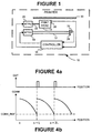
- Figure 1 shows a printer 10 including a shaft 12, a motor 14 (and gear train) and a controller 16 for the motor 14.
- the motor 14 rotates the shaft 12 under control of the controller 16.
- the shaft 12 drives a roller (not shown), which feeds sheets of paper through the printer 10.
- the controller 16 uses feedback information to control the roller rotation position and angular rate and, therefore, the sheet at a desired position and feed rate.
- the feedback information includes angular position and rate of the shaft 12 and, therefore, the roller and the sheet.
- a print head 18 is moved across the sheet by a second motor 20 (and gear train) and linkage 22 (e.g., a belt drive).
- the second motor 20 is also controlled by the controller 16.
- the controller 16 uses feedback information such as linear rate of the print head 18 to control the second motor 20.
- a rotary optical encoder 24 and a linear optical encoder 26 provide the feedback information to the controller 16.
- the rotary encoder 24 does not include a systematically patterned encoder wheel
- the linear encoder 26 does not include a systematically patterned encoder strip.
- the rotary encoder 24 utilizes natural surface features on a disc 28 coupled to the shaft 12.
- the linear encoder 26 utilizes natural surface features on a fixed member 30 that is parallel to the motion of the print head 18.
- the fixed member 30 could be, for example, a strip or wall of the printer 10.
- the natural surface features of the disc 28 and strip 30 may include structural and finish features such as grains, rough texturing, digs, scratches, cracks and other defects in the surface.
- Other types of natural surface features may include (without limitation) machining marks, surface finish imperfections, surface finish features, and mold and extrusion marks. These natural surface features may be on any surface having visible features that are somewhat random in size, shape and/or position relative to one another. Ideally, the natural surface features will vary in size, shape and position relative to one another.
- the natural surface features may be on a bare substrate surface of the disc 28 or strip 30, on an outer surface of a film covering the substrate of the disc 28 or strip 30, on a substrate surface covered by a film, etc. Natural surface features may even include features beneath the substrate surface. Such natural features might be used if, for example, light is transmitted by the disc 28 or strip 30.
- the rotary encoder 24 illuminates an area of the disc 28 such that the natural surface features scatter light in many different directions. Resulting is a high number of domains of lightness and darkness that can be imaged.
- the rotary encoder 24 generates a sequence of data frames of the illuminated surface area. Successive data frames are then processed to determine a relative rotational motion of the disc 28 and the shaft 12.
- the linear encoder 26 illuminates an area of the member 30.
- the resulting domains of lightness and darkness are then imaged by the linear encoder 26.
- Successive data frames are then processed to determine a relative linear motion of the print head 18.
- FIG. 2 shows the rotary encoder 24 in greater detail.
- the rotary encoder 24 includes an illuminator 32 for generating a beam of light that grazes the disc 28 at a grazing angle ⁇ and illuminates an area A of the disc 28.
- the grazing angle ⁇ is the angle from the surface of the disc 28, or the complimentary angle of the angle of incidence.
- the light grazing the disc 28 is scattered by the random natural surface features of the surface and produces the high number of domains of lightness and darkness.
- the rotary encoder 24 further includes a photosensor array 36, such as a CCD or CMOS device, which captures images of the domains of lightness and darkness. The images could show the entire area A or only a portion thereof.
- the photosensor array 36 includes multiple pixels arranged in one or two dimensional array.
- a lens 34 might be used to image the light from all or part of the illuminated area A onto the photosensor array 36.
- the illuminator 32 may include one or more LEDs and integrated or separate projection optics. Such optics might include diffractive optic elements that homogenize the light emitted by the LEDs. Multiple LEDs might allow for a more uniform illumination than a single LED.
- the illuminator 32 may instead include one or more lasers or cavity resonant LEDs instead of regular LEDs.
- the lasers would generate coherent light.
- the LEDs in contrast, would generate non-coherent or only partially coherent light.
- wavelength of the light are dependent upon the surface being illuminated, the features being imaged, and the response of the photosensor array 36.
- the light could be visible, infrared, ultraviolet, narrow band or broadband.
- a shorter wavelength might be used for exciting a phosphorescing or fluorescing emission from a surface.
- the wavelength may be selectively chosen if the surface exhibits significant spectral dependence that can provide images having high contrast.
- the light could be collimated or non-collimated. Collimated light has been found to work well for grazing illumination in that it provides good contrast in surface features that derive from surface profile geometry (e.g., bumps, grooves) and surface structural elements (e.g., fibers comprising the surfaces of papers, fabrics, woods).
- surface profile geometry e.g., bumps, grooves
- surface structural elements e.g., fibers comprising the surfaces of papers, fabrics, woods.
- the photosensor array 36 During operation of the rotary encoder 24, grazing light illuminates the area A of the disc 28, and the photosensor array 36 generates a sequence of data frames representing at least a portion of the illuminated area A.
- the illuminated area A is a distance r from the center of rotation.
- the distance traversed across the photosensor array 36 is r ⁇ , where ⁇ us the incremental rotation of the shaft 12.
- a processor 38 processes the data frames that are generated by the photosensor array 36.
- the processor 38 of the rotary encoder 24 determines whether the shaft 12 has been rotated by an angular increment. There are a number of ways in which this can be determined. One such way is for the processor 38 to measure displacements of the shaft 12 by comparing successive images using a correlation method.
- the processor 38 outputs an electrical pulse each time the shaft 12 has been rotated by the angular increment The pulses are supplied to the controller 16.
- the photosensor array 36 and illuminator 32 are mounted to a printed circuit board (not shown).
- the printed circuit board and the lens 34 are mounted to the printer 10 in manner that keeps the illuminator 32, the lens 34, and the photosensor array 36 in optical alignment.
- the mounting is rigid and rugged to ensure that the optical alignment is maintained in a fixed relationship. If the processor 38 is implemented on a separate chip, it too may be mounted to the printed circuit board.
- the photosensor array 36 and the processor 38 may be fabricated on separate chips. In the alternative, the processor 38 may be integrated with the photosensor array 36 on a single chip 40.
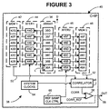
- Figure 3 shows a chip 40 including a processor 38 that is integrated with a photosensor array 36.
- the photosensor array 36 includes multiple pixels 36A to 36G that are spaced at a regular intervals.
- the pixels 36A to 36G are all of the same size. Pixel pitch is denoted by the letter L. Seven pixels 36A to 36G in a linear array are shown by way of example.
- the pixels 36A to 36G do not discern individual features of the target 28 or 30.
- the individual features are typically larger than each pixel 36A to 36G.
- each pixel 36A to 36G effectively measures an intensity level of a portion of an image or projection of a surface feature within its field of view.
- Output signals generated by the set of pixels 36A to 36G indicate the contrast variations of the imaged surface features.
- a data frame for the photosensor array 36 shown in Figure 3 includes the seven intensity levels measured by the seven pixels 36A to 36G.
- the pixels 36A to 36G typically detect different intensity levels due to random size, shape and distribution of the surface features and a randomness of the scattering by the surface features. As the shaft 12 is rotated or the print head 18 is moved, different features will come into view of the pixels 36A to 36G and intensity levels of the pixels 36A to 36G will change.
- Table I provides an example of changing intensity levels in images taken at an initial position x, a second position x+L and a third position x+2L, where x is the initial position of a point within the image or projection of area A, x+L is the position of the point after being moved a distance of one pixel pitch L from the initial position x, and x+2L is the position of the point after being moved a distance of twice the pixel pitch from the initial position x.
- the shaft 12 is rotated or the print head 18 is moved, the point x will move across the pixels 36A to 36G in a direction D, which is parallel or tangent to the direction of relative motion between the area A and the photosensor array 36.
- the intensity pattern (100, 125, 166, 123, 111) shifts by one pixel pitch L between the initial and second positions, and that it shifts by twice the pixel pitch 2L between the initial and third positions.
- the first to fifth pixels 36A to 36E will detect the same intensity levels at the initial position x that the second to sixth pixels 36B to 36F will detect at the second position x+L, and that the third to seventh pixels 36C to 36G will detect at the third position x+2L. This property will be used to determine when the shaft 12 or print head 18 has moved by an incremental amount.
- the processor 38 uses a correlation method to determine when the intensity pattern has shifted by a pixel length L.
- the processor 38 includes a first memory device 42 including multiple registers 42B to 42G for storing a current intensity pattern.
- the registers 42B to 42G of the first memory device 42 receive intensity values from the last six pixels 36B to 36G of the photosensor array 36 by way of a first transfer device 44 (which includes elements 44B to 44G).
- the processor 38 further includes a second memory device 46 including multiple registers 46A to 46F for storing a reference intensity pattern by way of a second transfer device 45 (which includes elements 45A to 45F).
- the intensity data stored in the second memory device 46 represents a current reference image corresponding to a given position of the shaft 12 or print head 18. This reference image or intensity pattern also represents a predicted intensity pattern of the image after a point within the image of projection of the area A has moved a distance of one pixel pitch L along the photosensor array 36.
- the intensity pattern of the last six pixels 36B to 36G is stored in the first memory device 42, and the intensity pattern of the first six pixels 36A to 36F is stored in the second memory device 46.
- the first memory device 42 is constantly updated with new intensity patterns from the last six pixels 36B to 36G.
- the second memory device 46 is not updated as often. When a relative distance of one pixel length has been traversed, the intensity pattern stored in the first memory device 42 will be about the same as the intensity pattern stored in the second memory device 46.
- the processor 38 further includes a correlator 48 for determining whether the current intensity pattern stored and read from the first memory device 42 (via path 50) matches the reference intensity pattern stored and read from the second memory device 46 (via path 52).
- System clocks 54 send clocking signals to the first transfer device 44 and the correlator 48 (first one, then the other) at a rate high enough to ensure that images or projections of the area A have moved only a small fraction of the pixel pitch length L between clocking instances.
- An output of the correlator 48 provides a signal CORR indicating the sum-of-squared-difference C.
- the processor 38 further includes a comparator 56 that compares the correlator signal CORR to a reference signal CORR_REF.
- the comparator 56 asserts a low voltage level on its output 58 when the correlator signal CORR exceeds the reference signal CORR_REF, and the comparator 56 asserts a high voltage level on its output 58 when the correlator signal CORR falls below the reference signal CORR_REF.
- the reference signal CORR_REF is chosen by design to lie slightly above the smallest value of the correlator signal CORR.
- the elements 45A to 45F of the second transfer device 45 are triggered by way of the comparator output signal OUT and by way of a reference sample clock controller 60.
- the second transfer device 45 is thus triggered or activated, the current pixel values are stored in the second memory device 46. Because the intensity patterns in the two memory devices 42 and 46 will no longer match, the correlator signal CORR will immediately go high again, thereby changing the output signal OUT of the comparator 56 back to the low level. Thus, in a single action, the rising edge of a comparator output pulse OUT is generated and a new reference intensity pattern is stored in the second memory device 46.
- a pulse OUT is supplied on the output 58 of the processor 38.
- the actual image distance traveled before a pulse is generated may be determined by the way in which the pixels 36A to 36F are transferred to the second memory device 46. If only the first three pixels were transferred, and the last three pixels were correlated to the reference pattern, a pulse would represent N-3 pixel lengths of motion (where N is the number of rows in the photosensor array 36). Thus, the amount of incremental motion can be made to correspond to multiples of one or more of pixel-pitch-lengths in the image space of the photosensor array 36.
- the processor 38 may be designed to detect motion in an opposite direction as well by performing a second correlation operation involving additional transfer and memory elements.
- the detectability of some random surface features can be enhanced by utilizing illumination at a grazing angle (i.e., a high incidence angle relative to the surface normal).
- the grazing angle might be less than 15 degrees for a smooth, finely-textured surface or a slightly rough surface constructed of fibers or particles. These surfaces, unlike polished surfaces, will reveal darker darks under grazing illumination. Generally, higher grazing angles will result in a lower signal-to-noise (SNR) ratio from these surfaces, and lower grazing angles will result in a higher SNR ratio despite a lower signal. The higher SNR will make it easier to observe and detect the random features and will be less prone to errors caused by noise. For a printed surface or one that has many different zones of optical absorption, lower incidence angles (e.g., 30 to 60 degrees) may be used.
- the detectability of the natural surface features of the target 28 or 30 can be enhanced by random-like texturing.
- the targets 28 or 30 could be abraded, sanded, etched or machined.
- FIG 6 shows the linear encoder 26 in greater detail.
- the linear encoder 26 also includes an illuminator 32, lens 34 and chip 40 having an integrated detector array 36 and processor 38.
- the illuminator 32, lens 34, detector array 36 and processor 38 of the linear encoder 26 are adapted to image the natural surface features on the fixed member 30.
- the processor 38 of the linear encoder 26 outputs an electrical pulse when the print head 18 has moved by a known increment. The pulses are supplied to the controller 16 (see Figure 1).
- encoders 24 and 26 that do not require the use of systematically patterned targets for detecting relative motion. Eliminating the use of systematically patterned targets simplifies manufacture and assembly, reduces the cost of labor and material and, consequently, reduces the cost of a printer. Particularly effective in reducing cost is the ability to utilize a naturally textured surface of a structural or rotary member that is already part of the printer.
- the targets 28 and 30 of the encoders 24 and 26 are more robust to contamination and surface damage. Eliminating the use of systematically patterned targets also reduces the number of encoder specifications. For instance, eliminating rotational alignment specifications can lead to greater accuracy and precision of angular measurements.
- a processor 38 that uses a correlation technique to generate pulsed, incremental outputs from the use of the targets (member, disc) above.
- the processor 38 could be wired to correlate pixel movements of one pixel or more than one pixel.
- dead bands between correlations can be significantly reduced.
- optical encoders 24 ad 26 are not limited to use in printers.
- the invention could be applied to scanners, computers, computer peripherals, computer appliances, information appliances and other appliances.
- the generalized method of Figure 5 would be applied to these machines as follows: illuminate an area of the target surface such that random, natural surface features within the area can be imaged by the photosensor array 36 (block 200); and process successive data frames generated by the photosensor array 36 to determine a relative movement of the illuminated surface area (block 202).
- optical encoders 24 and 26 are not limited to the specific embodiments described above.
- other correlation algorithms could be used.
- Other algorithms might include sum of products, normalized sums of products, root-mean-sums-of-squared-differences, normalized sums of squared differences, sums of absolute differences, normalized sums of absolute differences, etc.
- Analog or digital approaches for capturing, transferring and storing the images and for computing correlations of the images could be used.
- the photosensor elements could be read as continuous data or as integrated and sampled data.
- the transfer devices could utilize sample-and-hold circuits in parallel or could use multiplexing and de-multiplexing circuits for serial operation.
- the lens 34 could be a telecentric lens.
- a telecentric lens gives depth of field while holding magnification constant. Consequently, the telecentric lens relaxes positioning requirement and manufacturing tolerance and focus of the encoder.
- the lens 34 may be eliminated if the photosensor array 36 can be moved very close to the target 28 or 30 or transmissive illumination can be well-collimated.
- the disc 28 is optional. If a portion of a circumference or end face of the shaft 12 is large enough to be imaged, the disc is not needed. However, using the disc to increase the imageable surface will increase accuracy of the relative motion measurement.
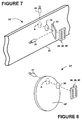
- the target 28 or 30 could be illuminated by specular illumination.
- Direct specular illumination could be provided by illumination directed normally onto the area A by way of a beamsplitter 33 (see Figure 7), or in a complementary arrangement the positions of the illuminator 32 and the photosensor array 36 could be exchanged.
- An alternative LED 35 could provide edge illumination to fill the thickness of the target 30 with light.
- a target 28' could be made of a transmissive material.
- the target 28' could be made of clear or translucent plastic.
- An illuminator 31 would be on one side of the plastic target 28', and the photosensor array 36 would be on an opposite side of the plastic target 28' (see Figure 8).
- the illuminator could be eliminated altogether by using a luminous target such as a self-illuminating target, a phosphorescent target or a fluorescent target.
- a luminous target such as a self-illuminating target, a phosphorescent target or a fluorescent target.
- a phosphorescent target has a certain granularity that can be detected, and a fluorescent target has imperfections that can be detected.
- the photosensor array 36 could instead have a different geometry, such as a circularly symmetric geometry for rotary movement. Polar coordinates would be used to measure the distance moved.
- the encoders 24 and 26 may include a processor 38' that indicates a rate of motion.
- the steps taken by such a processor 38' are shown in Figure 9.
- the processor 38' measures rate of the target motion by computing a spatial gradient of pixel data (block 300); computing a temporal gradient of pixel data (block 302); and computing a ratio of the temporal gradient to the spatial gradient (block 304). The ratio is indicative of the relative rate of displacement of the target area A on the target 28 or 30.
- the spatial gradient could be computed as the average difference in intensity between adjacent pixels in an image, taking the differences in one direction along the column(s) of pixels.
- the difference distance is the pixel pitch length L.
- the processor 38' computes a difference in pixel intensities. Then the processor 38' sums these differences over the six pairs and divides by 6 and divides by L.
- the temporal gradient could be computed as the average in the changes of pixel intensities between images in a sequential pair of captured images. For each pixel, the processor 38' determines a difference in intensity value over two consecutive images or data frames, sums these differences over all pixel positions, and divides the intensity difference by the number of pixels in an image and the time between frames. For example, if the average change in pixel intensity value over two consecutive data frames is two units, and the time between two frames is ten microseconds, the average value of the temporal gradient or temporal rate of intensity change is 0.2 units/ microsecond. Dividing the average temporal gradient of 0.2 units/microsecond by the average spatial gradient of 2.0 units/micrometer yields a rate of image displacement of 0.1 micrometers per microsecond.
- patterned targets may nevertheless be used. Adding a unique and identifiable pattern to the target (e.g., adding a systematic fabricated pattern that is non-repeating over some maximum travel or over a full revolution) allows absolute measurements to be made.
- a processor 38'' would look for an additional correlation of the fixed pattern on the target with a permanent reference target pattern. Thus, the processor 38'' would look for a first correlation between current and previously captured patterns (block 400), output a pulse when a first correlation is found (block 402), look for a second correlation between a current pattern in the data frame and a permanent reference target pattern stored in memory (block 404) and output a signal when the second correlation is found (block 406) (see Figure 10).
- An absolute measurement is thereby made when the second correlation is found.
- a non-repeating absolute reference pattern is a printed density that varies as a sine wave with continuously increasing spatial frequency. This could be printed on top of a random texture. Another example would be a pair of diverging lines over a random field.
Landscapes
- Physics & Mathematics (AREA)
- General Physics & Mathematics (AREA)
- Length Measuring Devices By Optical Means (AREA)
- Optical Transform (AREA)
Applications Claiming Priority (2)
| Application Number | Priority Date | Filing Date | Title |
|---|---|---|---|
| US09/264,063 US6246050B1 (en) | 1999-03-08 | 1999-03-08 | Optical encoders using non-patterned targets |
| US264063 | 2002-10-03 |
Publications (3)
| Publication Number | Publication Date |
|---|---|
| EP1037020A2 true EP1037020A2 (fr) | 2000-09-20 |
| EP1037020A3 EP1037020A3 (fr) | 2001-08-08 |
| EP1037020B1 EP1037020B1 (fr) | 2007-05-09 |
Family
ID=23004408
Family Applications (1)
| Application Number | Title | Priority Date | Filing Date |
|---|---|---|---|
| EP00301645A Expired - Lifetime EP1037020B1 (fr) | 1999-03-08 | 2000-03-01 | Détection optique de déplacements |
Country Status (4)
| Country | Link |
|---|---|
| US (1) | US6246050B1 (fr) |
| EP (1) | EP1037020B1 (fr) |
| JP (1) | JP2000283795A (fr) |
| DE (1) | DE60034723T2 (fr) |
Cited By (7)
| Publication number | Priority date | Publication date | Assignee | Title |
|---|---|---|---|---|
| EP1580535A2 (fr) * | 2004-03-26 | 2005-09-28 | Hofmann Mess- und Auswuchttechnik GmbH & Co. KG | Procédé et appareil de détection d'un déplacement relatif entre un capteur et un corps avec une structure de surface |
| EP1526535A3 (fr) * | 2003-10-09 | 2007-09-19 | Hewlett-Packard Development Company, L.P. | Méthode et système d'utilisation d'un ensemble de détecteurs optiques pour commander un dispositif d'étiquettage |
| WO2008039066A1 (fr) * | 2006-09-27 | 2008-04-03 | Paccus Interfaces B.V. | Détecteur de déplacement angulaire |
| US8532338B2 (en) | 2004-07-06 | 2013-09-10 | Hewlett-Packard Development Company, L.P. | System and method for compensating for motion blur in optical navigation |
| WO2014090318A1 (fr) * | 2012-12-13 | 2014-06-19 | Carl Zeiss Industrielle Messtechnik Gmbh | Appareil comprenant une partie d'appareil mobile, en particulier appareil de mesure de coordonnées ou machine-outil |
| EP1662233A3 (fr) * | 2004-11-24 | 2016-06-08 | Canon Kabushiki Kaisha | Echelle de mesure optique et codeur optique utilisant celle-ci. |
| CN111750909A (zh) * | 2019-03-28 | 2020-10-09 | 株式会社三丰 | 光编码器和光编码器的计算方法 |
Families Citing this family (63)
| Publication number | Priority date | Publication date | Assignee | Title |
|---|---|---|---|---|
| WO2002039386A2 (fr) * | 2000-11-10 | 2002-05-16 | British Telecommunications Public Limited Company | Caracterisation d'images |
| US6765195B1 (en) | 2001-05-22 | 2004-07-20 | The United States Of America As Represented By The Administrator Of The National Aeronautics And Space Administration | Method and apparatus for two-dimensional absolute optical encoding |
| US6965685B1 (en) * | 2001-09-04 | 2005-11-15 | Hewlett-Packard Development Company, Lp. | Biometric sensor |
| JP4038812B2 (ja) * | 2001-12-27 | 2008-01-30 | ソニー株式会社 | データ処理装置およびデータ処理方法、プログラムおよび記録媒体、並びにデータ処理システム |
| US6664995B2 (en) | 2002-02-06 | 2003-12-16 | Brady Worldwide, Inc. | Label media-specific plotter cutter depth control |
| US6788324B2 (en) * | 2002-02-06 | 2004-09-07 | Brady Worldwide, Inc. | Encoder-based control of printhead firing in a label printer |
| US6742858B2 (en) * | 2002-02-06 | 2004-06-01 | Brady Worldwide, Inc. | Label printer-cutter with mutually exclusive printing and cutting operations |
| US6768502B2 (en) | 2002-02-06 | 2004-07-27 | Brady Worldwide, Inc. | Label printer dot line registration assembly |
| US6616360B2 (en) | 2002-02-06 | 2003-09-09 | Brady Worldwide, Inc. | Label printer end and plotter cutting assembly |
| US6860658B2 (en) | 2002-02-15 | 2005-03-01 | Brady Worldwide, Inc. | Ribbon wiper |
| US7060968B1 (en) | 2002-06-04 | 2006-06-13 | The United States Of America As Represented By The Administrator Of The National Aeronautics And Space Administration | Method and apparatus for optical encoding with compressible imaging |
| US20040135076A1 (en) * | 2003-01-15 | 2004-07-15 | Xerox Corporation | Method and apparatus for obtaining a high quality sine wave from an analog quadrature encoder |
| US7102122B2 (en) * | 2003-05-29 | 2006-09-05 | Hewlett-Packard Development Company, L.P. | Methods and means for using a photosensor as an encoder and a trigger |
| US7129858B2 (en) * | 2003-10-10 | 2006-10-31 | Hewlett-Packard Development Company, L.P. | Encoding system |
| US7773070B2 (en) | 2004-05-21 | 2010-08-10 | Cypress Semiconductor Corporation | Optical positioning device using telecentric imaging |
| US7189909B2 (en) | 2004-11-23 | 2007-03-13 | Román Viñoly | Camera assembly for finger board instruments |
| WO2007030731A2 (fr) * | 2005-09-07 | 2007-03-15 | Nr Laboratories, Llc | Systeme et procede de detection de position |
| US7378643B2 (en) * | 2006-04-24 | 2008-05-27 | Avago Technologies General Ip Pte Ltd | Optical projection encoder with patterned mask |
| US7748839B2 (en) * | 2006-05-09 | 2010-07-06 | Lexmark International, Inc. | Handheld printing with reference indicia |
| US7682017B2 (en) * | 2006-05-10 | 2010-03-23 | Lexmark International, Inc. | Handheld printer minimizing printing defects |
| DE102009009789B4 (de) * | 2009-02-20 | 2015-08-13 | Phoenix Contact Gmbh & Co. Kg | Bewegungssensor |
| TWI387319B (zh) * | 2009-06-02 | 2013-02-21 | Novatek Microelectronics Corp | 影像處理電路及方法 |
| US8493569B2 (en) * | 2010-12-27 | 2013-07-23 | Mitutoyo Corporation | Optical encoder readhead configuration with phosphor layer |
| WO2014006147A1 (fr) * | 2012-07-04 | 2014-01-09 | Hexagon Technology Center Gmbh | Capteur de position optique présentant une mémoire analogique |
| US9542016B2 (en) | 2012-09-13 | 2017-01-10 | Apple Inc. | Optical sensing mechanisms for input devices |
| US9753436B2 (en) | 2013-06-11 | 2017-09-05 | Apple Inc. | Rotary input mechanism for an electronic device |
| EP3514665A1 (fr) | 2013-08-09 | 2019-07-24 | Apple Inc. | Commutateur tactile pour dispositif électronique |
| JP5999584B2 (ja) * | 2013-11-05 | 2016-09-28 | 株式会社安川電機 | エンコーダ、エンコーダ付きモータ、サーボシステム |
| US9488503B2 (en) * | 2014-01-03 | 2016-11-08 | Vernier Software & Technology, Llc | Cart movement detection system for a dynamics track |
| US10048802B2 (en) | 2014-02-12 | 2018-08-14 | Apple Inc. | Rejection of false turns of rotary inputs for electronic devices |
| US10929699B2 (en) * | 2014-03-13 | 2021-02-23 | Pixart Imaging Inc. | Optical encoder capable of identifying absolute positions |
| US10380445B2 (en) | 2014-03-13 | 2019-08-13 | Pixart Imaging Inc. | Optical encoder capable of identifying absolute positions and operating method thereof |
| TWI507664B (zh) * | 2014-03-13 | 2015-11-11 | Pixart Imaging Inc | 光學編碼器及其運作方法 |
| US10210412B2 (en) | 2014-03-13 | 2019-02-19 | Pixart Imaging Inc. | Optical encoder capable of identifying absolute positions and operating method thereof |
| US9797752B1 (en) | 2014-07-16 | 2017-10-24 | Apple Inc. | Optical encoder with axially aligned sensor |
| US10190891B1 (en) * | 2014-07-16 | 2019-01-29 | Apple Inc. | Optical encoder for detecting rotational and axial movement |
| US9797753B1 (en) | 2014-08-27 | 2017-10-24 | Apple Inc. | Spatial phase estimation for optical encoders |
| US10066970B2 (en) | 2014-08-27 | 2018-09-04 | Apple Inc. | Dynamic range control for optical encoders |
| KR102130259B1 (ko) | 2014-09-02 | 2020-07-03 | 애플 인크. | 웨어러블 전자 디바이스 |
| WO2016141228A1 (fr) | 2015-03-05 | 2016-09-09 | Apple Inc. | Encodeur optique doté de propriétés optiques dépendant de la direction |
| JP6479997B2 (ja) | 2015-03-08 | 2019-03-06 | アップル インコーポレイテッドApple Inc. | 回転可能かつ並進可能な入力機構のための圧縮可能な封止 |
| US10724947B2 (en) | 2015-04-14 | 2020-07-28 | Cognex Corporation | System and method for acquiring images of surface texture |
| US9952682B2 (en) | 2015-04-15 | 2018-04-24 | Apple Inc. | Depressible keys with decoupled electrical and mechanical functionality |
| US10018966B2 (en) | 2015-04-24 | 2018-07-10 | Apple Inc. | Cover member for an input mechanism of an electronic device |
| US9891651B2 (en) | 2016-02-27 | 2018-02-13 | Apple Inc. | Rotatable input mechanism having adjustable output |
| US10551798B1 (en) | 2016-05-17 | 2020-02-04 | Apple Inc. | Rotatable crown for an electronic device |
| US10061399B2 (en) | 2016-07-15 | 2018-08-28 | Apple Inc. | Capacitive gap sensor ring for an input device |
| US10019097B2 (en) | 2016-07-25 | 2018-07-10 | Apple Inc. | Force-detecting input structure |
| US10551223B2 (en) * | 2017-03-20 | 2020-02-04 | Tt Electronics Plc | Method and apparatus for configurable photodetector array patterning for optical encoders |
| US10664074B2 (en) | 2017-06-19 | 2020-05-26 | Apple Inc. | Contact-sensitive crown for an electronic watch |
| US10962935B1 (en) | 2017-07-18 | 2021-03-30 | Apple Inc. | Tri-axis force sensor |
| JP7028652B2 (ja) | 2018-01-16 | 2022-03-02 | 株式会社ミツトヨ | 測定装置 |
| US11360440B2 (en) | 2018-06-25 | 2022-06-14 | Apple Inc. | Crown for an electronic watch |
| US11561515B2 (en) | 2018-08-02 | 2023-01-24 | Apple Inc. | Crown for an electronic watch |
| US11181863B2 (en) | 2018-08-24 | 2021-11-23 | Apple Inc. | Conductive cap for watch crown |
| CN211293787U (zh) | 2018-08-24 | 2020-08-18 | 苹果公司 | 电子表 |
| US11194298B2 (en) | 2018-08-30 | 2021-12-07 | Apple Inc. | Crown assembly for an electronic watch |
| CN209625187U (zh) | 2018-08-30 | 2019-11-12 | 苹果公司 | 电子手表和电子设备 |
| US11194299B1 (en) | 2019-02-12 | 2021-12-07 | Apple Inc. | Variable frictional feedback device for a digital crown of an electronic watch |
| US11260678B2 (en) | 2019-06-26 | 2022-03-01 | Xerox Corporation | Print substrate optical motion sensing and dot clock generation |
| US11550268B2 (en) | 2020-06-02 | 2023-01-10 | Apple Inc. | Switch module for electronic crown assembly |
| US11635786B2 (en) | 2020-06-11 | 2023-04-25 | Apple Inc. | Electronic optical sensing device |
| US12092996B2 (en) | 2021-07-16 | 2024-09-17 | Apple Inc. | Laser-based rotation sensor for a crown of an electronic watch |
Citations (2)
| Publication number | Priority date | Publication date | Assignee | Title |
|---|---|---|---|---|
| WO1984001027A1 (fr) * | 1982-09-01 | 1984-03-15 | Rosemount Eng Co Ltd | Dispositif de mesure de position |
| EP0479759A1 (fr) * | 1990-10-05 | 1992-04-08 | RSF-Elektronik Gesellschaft m.b.H. | Procédé et dispositif pour la mesure de longueurs ou d'angles |
Family Cites Families (9)
| Publication number | Priority date | Publication date | Assignee | Title |
|---|---|---|---|---|
| US4631400A (en) * | 1984-01-20 | 1986-12-23 | California Institute Of Technology | Correlating optical motion detector |
| US4794384A (en) * | 1984-09-27 | 1988-12-27 | Xerox Corporation | Optical translator device |
| US5089712A (en) | 1989-06-08 | 1992-02-18 | Hewlett-Packard Company | Sheet advancement control system detecting fiber pattern of sheet |
| US5149980A (en) | 1991-11-01 | 1992-09-22 | Hewlett-Packard Company | Substrate advance measurement system using cross-correlation of light sensor array signals |
| US5578813A (en) | 1995-03-02 | 1996-11-26 | Allen; Ross R. | Freehand image scanning device which compensates for non-linear movement |
| US5686720A (en) | 1995-03-02 | 1997-11-11 | Hewlett Packard Company | Method and device for achieving high contrast surface illumination |
| US5703353A (en) | 1996-01-25 | 1997-12-30 | Hewlett-Packard Company | Offset removal and spatial frequency band filtering circuitry for photoreceiver signals |
| US5729008A (en) | 1996-01-25 | 1998-03-17 | Hewlett-Packard Company | Method and device for tracking relative movement by correlating signals from an array of photoelements |
| US5965879A (en) * | 1997-05-07 | 1999-10-12 | The United States Of America As Represented By The Administrator Of The National Aeronautics And Space Administration | Method and apparatus for ultra-high-sensitivity, incremental and absolute optical encoding |
-
1999
- 1999-03-08 US US09/264,063 patent/US6246050B1/en not_active Expired - Fee Related
-
2000
- 2000-03-01 DE DE60034723T patent/DE60034723T2/de not_active Expired - Lifetime
- 2000-03-01 EP EP00301645A patent/EP1037020B1/fr not_active Expired - Lifetime
- 2000-03-08 JP JP2000063422A patent/JP2000283795A/ja not_active Withdrawn
Patent Citations (2)
| Publication number | Priority date | Publication date | Assignee | Title |
|---|---|---|---|---|
| WO1984001027A1 (fr) * | 1982-09-01 | 1984-03-15 | Rosemount Eng Co Ltd | Dispositif de mesure de position |
| EP0479759A1 (fr) * | 1990-10-05 | 1992-04-08 | RSF-Elektronik Gesellschaft m.b.H. | Procédé et dispositif pour la mesure de longueurs ou d'angles |
Cited By (13)
| Publication number | Priority date | Publication date | Assignee | Title |
|---|---|---|---|---|
| EP1526535A3 (fr) * | 2003-10-09 | 2007-09-19 | Hewlett-Packard Development Company, L.P. | Méthode et système d'utilisation d'un ensemble de détecteurs optiques pour commander un dispositif d'étiquettage |
| US7483184B2 (en) | 2003-10-09 | 2009-01-27 | Hewlett-Packard Development Company, L.P. | Method and system for using an optical sensor array to control a labeling device |
| US7676119B2 (en) | 2003-10-09 | 2010-03-09 | Hewlett-Packard Development Company, L.P. | Method and system for using an optical sensor array to control a labeling device |
| EP1580535A3 (fr) * | 2004-03-26 | 2006-10-18 | Hofmann Mess- und Auswuchttechnik GmbH & Co. KG | Procédé et appareil de détection d'un déplacement relatif entre un capteur et un corps avec une structure de surface |
| EP1580535A2 (fr) * | 2004-03-26 | 2005-09-28 | Hofmann Mess- und Auswuchttechnik GmbH & Co. KG | Procédé et appareil de détection d'un déplacement relatif entre un capteur et un corps avec une structure de surface |
| US8532338B2 (en) | 2004-07-06 | 2013-09-10 | Hewlett-Packard Development Company, L.P. | System and method for compensating for motion blur in optical navigation |
| EP1662233A3 (fr) * | 2004-11-24 | 2016-06-08 | Canon Kabushiki Kaisha | Echelle de mesure optique et codeur optique utilisant celle-ci. |
| WO2008039066A1 (fr) * | 2006-09-27 | 2008-04-03 | Paccus Interfaces B.V. | Détecteur de déplacement angulaire |
| WO2014090318A1 (fr) * | 2012-12-13 | 2014-06-19 | Carl Zeiss Industrielle Messtechnik Gmbh | Appareil comprenant une partie d'appareil mobile, en particulier appareil de mesure de coordonnées ou machine-outil |
| CN104870935A (zh) * | 2012-12-13 | 2015-08-26 | 卡尔蔡司工业测量技术有限公司 | 具有可运动式设备部分的设备尤其坐标测量设备或工具机 |
| US9851197B2 (en) | 2012-12-13 | 2017-12-26 | Carl Zeiss Industrielle Messtechnik Gmbh | Device with displaceable device part, in particular coordinate measuring device or machine tool |
| CN104870935B (zh) * | 2012-12-13 | 2018-07-31 | 卡尔蔡司工业测量技术有限公司 | 具有可运动式设备部分的设备尤其坐标测量设备或工具机 |
| CN111750909A (zh) * | 2019-03-28 | 2020-10-09 | 株式会社三丰 | 光编码器和光编码器的计算方法 |
Also Published As
| Publication number | Publication date |
|---|---|
| DE60034723D1 (de) | 2007-06-21 |
| US6246050B1 (en) | 2001-06-12 |
| EP1037020A3 (fr) | 2001-08-08 |
| EP1037020B1 (fr) | 2007-05-09 |
| JP2000283795A (ja) | 2000-10-13 |
| DE60034723T2 (de) | 2007-12-06 |
Similar Documents
| Publication | Publication Date | Title |
|---|---|---|
| US6246050B1 (en) | Optical encoders using non-patterned targets | |
| EP1160538B1 (fr) | Capteur de position fondé sur des images de granulation ayant une sensitibilité ameliorée concernant l'arrangement géometrique et la dépendence en direction | |
| US6781694B2 (en) | Two-dimensional scale structures and method usable in an absolute position transducer | |
| US6664535B1 (en) | Scale structures and methods usable in an absolute position transducer | |
| US6867412B2 (en) | Scale structures and methods usable in an absolute position transducer | |
| EP1473549B1 (fr) | Systeme et méthode de positionnement absolu avec motif quasi-aleatoire répété | |
| KR101701535B1 (ko) | 위치 인코더 장치 | |
| US11199395B2 (en) | Profile inspection system for threaded and axial components | |
| TW420928B (en) | System for measuring the velocity, displacement and strain on a moving surface or web of material | |
| KR100571346B1 (ko) | 각 인코더 | |
| US7763875B2 (en) | System and method for sensing position utilizing an uncalibrated surface | |
| US7102122B2 (en) | Methods and means for using a photosensor as an encoder and a trigger | |
| WO1998053327A1 (fr) | Procede et dispositif de mesure de deplacement sans contact | |
| US6220686B1 (en) | Measurement of paper speed using laser speckle detection | |
| EP2275782A1 (fr) | Encodeur entièrement rotatif haute résolution | |
| EP0926631A2 (fr) | Mesurage de la vitesse du papier utilisant la détection de la granulation produite par laser | |
| EP3850310B1 (fr) | Dispositif de mesure | |
| JP2003166855A (ja) | 光学式エンコーダ | |
| US6181423B1 (en) | Linear encoder providing engagement by engraving | |
| AU2001265710B2 (en) | Position encoder using statistically biased pseudorandom sequence | |
| Mahadi et al. | Precise Measurement of Displacement Using Pixels | |
| SE514004C2 (sv) | Tjockleksmätning med en detektor genom belysning av två ytor hos ett föremål, anordning, apparat och metod |
Legal Events
| Date | Code | Title | Description |
|---|---|---|---|
| PUAI | Public reference made under article 153(3) epc to a published international application that has entered the european phase |
Free format text: ORIGINAL CODE: 0009012 |
|
| AK | Designated contracting states |
Kind code of ref document: A2 Designated state(s): DE FR GB |
|
| AX | Request for extension of the european patent |
Free format text: AL;LT;LV;MK;RO;SI |
|
| RAP1 | Party data changed (applicant data changed or rights of an application transferred) |
Owner name: HEWLETT-PACKARD COMPANY, A DELAWARE CORPORATION |
|
| PUAL | Search report despatched |
Free format text: ORIGINAL CODE: 0009013 |
|
| AK | Designated contracting states |
Kind code of ref document: A3 Designated state(s): AT BE CH CY DE DK ES FI FR GB GR IE IT LI LU MC NL PT SE |
|
| AX | Request for extension of the european patent |
Free format text: AL;LT;LV;MK;RO;SI |
|
| RIC1 | Information provided on ipc code assigned before grant |
Free format text: 7G 01D 5/347 A, 7G 01D 5/36 B |
|
| 17P | Request for examination filed |
Effective date: 20020207 |
|
| AKX | Designation fees paid |
Free format text: DE FR GB |
|
| GRAP | Despatch of communication of intention to grant a patent |
Free format text: ORIGINAL CODE: EPIDOSNIGR1 |
|
| GRAS | Grant fee paid |
Free format text: ORIGINAL CODE: EPIDOSNIGR3 |
|
| GRAA | (expected) grant |
Free format text: ORIGINAL CODE: 0009210 |
|
| AK | Designated contracting states |
Kind code of ref document: B1 Designated state(s): DE FR GB |
|
| REG | Reference to a national code |
Ref country code: GB Ref legal event code: FG4D |
|
| REF | Corresponds to: |
Ref document number: 60034723 Country of ref document: DE Date of ref document: 20070621 Kind code of ref document: P |
|
| ET | Fr: translation filed | ||
| PLBE | No opposition filed within time limit |
Free format text: ORIGINAL CODE: 0009261 |
|
| STAA | Information on the status of an ep patent application or granted ep patent |
Free format text: STATUS: NO OPPOSITION FILED WITHIN TIME LIMIT |
|
| 26N | No opposition filed |
Effective date: 20080212 |
|
| PGFP | Annual fee paid to national office [announced via postgrant information from national office to epo] |
Ref country code: FR Payment date: 20100406 Year of fee payment: 11 |
|
| PGFP | Annual fee paid to national office [announced via postgrant information from national office to epo] |
Ref country code: GB Payment date: 20100326 Year of fee payment: 11 |
|
| PGFP | Annual fee paid to national office [announced via postgrant information from national office to epo] |
Ref country code: DE Payment date: 20100329 Year of fee payment: 11 |
|
| GBPC | Gb: european patent ceased through non-payment of renewal fee |
Effective date: 20110301 |
|
| REG | Reference to a national code |
Ref country code: FR Ref legal event code: ST Effective date: 20111130 |
|
| PG25 | Lapsed in a contracting state [announced via postgrant information from national office to epo] |
Ref country code: DE Free format text: LAPSE BECAUSE OF NON-PAYMENT OF DUE FEES Effective date: 20111001 Ref country code: FR Free format text: LAPSE BECAUSE OF NON-PAYMENT OF DUE FEES Effective date: 20110331 |
|
| REG | Reference to a national code |
Ref country code: DE Ref legal event code: R119 Ref document number: 60034723 Country of ref document: DE Effective date: 20111001 |
|
| PG25 | Lapsed in a contracting state [announced via postgrant information from national office to epo] |
Ref country code: GB Free format text: LAPSE BECAUSE OF NON-PAYMENT OF DUE FEES Effective date: 20110301 |