EP1035289A2 - Gelenk, insbesondere zur Verbindung von Torblattlamellen - Google Patents
Gelenk, insbesondere zur Verbindung von Torblattlamellen Download PDFInfo
- Publication number
- EP1035289A2 EP1035289A2 EP00101378A EP00101378A EP1035289A2 EP 1035289 A2 EP1035289 A2 EP 1035289A2 EP 00101378 A EP00101378 A EP 00101378A EP 00101378 A EP00101378 A EP 00101378A EP 1035289 A2 EP1035289 A2 EP 1035289A2
- Authority
- EP
- European Patent Office
- Prior art keywords
- joint part
- joint
- base body
- approach
- extension
- Prior art date
- Legal status (The legal status is an assumption and is not a legal conclusion. Google has not performed a legal analysis and makes no representation as to the accuracy of the status listed.)
- Withdrawn
Links
Images


Classifications
-
- E—FIXED CONSTRUCTIONS
- E05—LOCKS; KEYS; WINDOW OR DOOR FITTINGS; SAFES
- E05D—HINGES OR SUSPENSION DEVICES FOR DOORS, WINDOWS OR WINGS
- E05D5/00—Construction of single parts, e.g. the parts for attachment
- E05D5/10—Pins, sockets or sleeves; Removable pins
-
- E—FIXED CONSTRUCTIONS
- E05—LOCKS; KEYS; WINDOW OR DOOR FITTINGS; SAFES
- E05D—HINGES OR SUSPENSION DEVICES FOR DOORS, WINDOWS OR WINGS
- E05D15/00—Suspension arrangements for wings
- E05D15/16—Suspension arrangements for wings for wings sliding vertically more or less in their own plane
- E05D15/24—Suspension arrangements for wings for wings sliding vertically more or less in their own plane consisting of parts connected at their edges
- E05D15/242—Hinge connections between the parts
-
- E—FIXED CONSTRUCTIONS
- E05—LOCKS; KEYS; WINDOW OR DOOR FITTINGS; SAFES
- E05D—HINGES OR SUSPENSION DEVICES FOR DOORS, WINDOWS OR WINGS
- E05D7/00—Hinges or pivots of special construction
- E05D7/10—Hinges or pivots of special construction to allow easy separation or connection of the parts at the hinge axis
- E05D7/1044—Hinges or pivots of special construction to allow easy separation or connection of the parts at the hinge axis in an axial direction
- E05D7/105—Hinges or pivots of special construction to allow easy separation or connection of the parts at the hinge axis in an axial direction requiring a specific angular position
-
- E—FIXED CONSTRUCTIONS
- E05—LOCKS; KEYS; WINDOW OR DOOR FITTINGS; SAFES
- E05D—HINGES OR SUSPENSION DEVICES FOR DOORS, WINDOWS OR WINGS
- E05D9/00—Flaps or sleeves specially designed for making from particular material, e.g. hoop-iron, sheet metal, plastics
- E05D9/005—Flaps or sleeves specially designed for making from particular material, e.g. hoop-iron, sheet metal, plastics from plastics
-
- E—FIXED CONSTRUCTIONS
- E05—LOCKS; KEYS; WINDOW OR DOOR FITTINGS; SAFES
- E05Y—INDEXING SCHEME ASSOCIATED WITH SUBCLASSES E05D AND E05F, RELATING TO CONSTRUCTION ELEMENTS, ELECTRIC CONTROL, POWER SUPPLY, POWER SIGNAL OR TRANSMISSION, USER INTERFACES, MOUNTING OR COUPLING, DETAILS, ACCESSORIES, AUXILIARY OPERATIONS NOT OTHERWISE PROVIDED FOR, APPLICATION THEREOF
- E05Y2900/00—Application of doors, windows, wings or fittings thereof
- E05Y2900/10—Application of doors, windows, wings or fittings thereof for buildings or parts thereof
- E05Y2900/106—Application of doors, windows, wings or fittings thereof for buildings or parts thereof for garages
Definitions
- the present invention relates to a joint, in particular for connecting Door leaf slats, with a first and a second connectable with this Joint part.
- the first joint part has a hook-shaped engagement element and the second joint part comprises a base body and an extending body Approach whose outside diameter is equal to or less than the inside diameter of the engaging element of the first joint part, wherein in the area between Base body and neck an extending in the longitudinal direction of the neck Breakthrough is provided, its length over the length of the engaging element of the first joint part.
- Such joints are relatively simple and allow one Reliable and secure connection, for example of door leaf slats of sectional doors.
- the hook-shaped engagement element is used to assemble the joint parts of the first joint part pushed over the neck of the second joint part until this with that extending in the longitudinal direction of the approach of the second joint part Breakthrough escapes. In this position, a rotary movement of the first or second joint part, the engagement of the engagement element in the Breakthrough causes a simple and reliable connection of both Joint parts is realized.
- Both joint parts can each have a base body, which is hook-shaped Engagement element or connected to the approach.
- the basic body the joint parts are usually provided with mounting holes that for holding fasteners for fastening the joint parts, for example serve on slats of a sectional door to be connected.
- both the engagement element and the extension of metal extending from the base body of the second joint part preferably made of steel.
- the engaging element as well as the approach are made by bending Appropriate steel straps made.
- Results from the use of steel the disadvantage is that the sliding effect between the touching surfaces of engagement element and approach of the joint parts is relatively low. This applies both to the sliding movement required when assembling the joint when pushing the engagement element onto the neck, as well as in particular for the sliding of the contacting surfaces of the engagement element and Approach when pivoting the assembled joint.
- this object is achieved by that in the assembled state of the hinge parts the contact surface with the Areas of the attachment of the second joint part forming engagement element at least are partially made of plastic.
- This has the advantage that the engagement element due to the favorable sliding properties of plastic with low friction compared to the corresponding area of the approach of the base body of the second joint part is pivotable.
- the approach of the second joint part has a cylindrical shape.
- the outside diameter of the cylindrical extension is below the inside diameter the hook-shaped engaging element or corresponds to its inside diameter, to push the engagement element onto the shoulder and thus a To allow connection of both joint parts.
- the approach of the second joint part can be produced by extrusion-coating of the base body is.
- the base body of the second joint part preferably made of steel.
- the edge area of the body is molded plastic. According to the invention extends between the Plastic-made approach and the main body of the breakthrough for inclusion of the hook-shaped engagement element of the first joint part.
- the approach of the base body of the second joint part releasably executed is. This has the advantage that the approach, for example, when damaged can be easily replaced without disassembly of the base body is required. This also makes it a suitable choice of the plastic material can be easily implemented.
- the base body of the second joint part can have a receptacle on which the approach can be postponed.
- the approach consists in the contact surface at least partially with the area forming the engagement element made of plastic.
- the detachable approach is attached to the mount before assembly of the second joint part pushed on and locked here in a suitable manner.
- a plastic encapsulation of the base body of the second joint part is at such an embodiment is not required. Rather, the approach and the base body of the second joint part is manufactured completely separately from one another and are put together after manufacture.
- the approach a pivotable hook on the edge of a recess of the second joint part can be locked. It can be a snap hook act that can be opened slightly to assemble the approach to ensure the reception of the base body of the second joint part. After being pushed open, the hook is pivoted back and in this way the approach securely connected to the base body of the second joint part.
- the base body of the second joint part can be curved be and receivable in a correspondingly curved groove of the approach his.
- both joint parts each have a base body, the base body mounting plates have with holes for receiving fasteners are provided.
- the mounting plates are secured using suitable for example screws or rivets, with the elements to be connected, especially connected with slats of sectional doors.
- the approach of the second joint part consists entirely of plastic.
- the choice of the one to be used Plastic depends on the respective requirements, for example, according to the desired strength and abrasion resistance.
- the plastic of the second joint part is polyamide is.
- Fig. 1 shows a perspective view of the first joint part 10, the base body 14 includes the mounting plate 16. In the edge area of the mounting plate 16 extends the hook-shaped engagement element 12.
- the first joint part 10 is made preferably made of steel, but other materials are of course also available applicable.
- mounting holes (not shown) be provided, by means of which the first joint part 10, for example on a lamella a sectional door leaf can be attached.
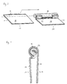
- FIG. 2 also shows the second joint part 20 in a perspective representation Base body 24, which includes the mounting plate 29. From the base body 24 or from the edge region of the mounting plate 29, the extension 22 extends Approach 22 is cylindrical and has an outer diameter that below the inner diameter of the engagement element 12 of the first joint part 10 lies. In the area between shoulder 22 and base body 24 extends in the longitudinal direction the approach 22 of the breakthrough 26, the length of the invention over the length of the engaging element 12 of the first joint part lies and that for receiving of the engaging element 12 in the assembled state of the joint parts 10, 20 serves.
- the approach 22 of the second joint part 20 is injection-molded with plastic, whereby as plastic Polyamide is used.
- plastic Polyamide instead of or in combination with polyamide other types of plastic or plastic mixtures can also be used.
- FIG. 3 shows an assembly illustration of the joint parts 10, 20 according to FIG. 1 and FIG. 2.
- the joint part 10 has been dropped, so that the hook-shaped engaging element is now on the underside of the mounting plate 16 of the first joint part 10 is arranged.
- the first joint part 10 is connected in this position to the second joint part 20 in that the hook-shaped engagement element 12 is pushed onto the neck 22 until this aligned with the opening 26.
- the first or the second Articulated part pivoted whereby the engaging element 12 into the opening 26 is introduced and thus a reliable connection of both joint parts 10, 20th will be produced.
- FIG. 5 shows the perspective view of the second joint part 20 in one another embodiment.
- the mounting plate 29 of the base body 24 of the second joint part 20 has a receptacle 28 in the edge region, which is connected to the Approach 22 is releasably connectable.
- the releasable extension 22 is pushed onto the receptacle 28 and then locked onto it.
- the approach 22 has a curved Groove 222 into which the curved receptacle 28 of the base body 24 of the second joint part 20 is inserted.
- the pivotable hook is located in a central region of the extension 22 220, which is shown enlarged in FIG. 7.
- the hook 220 is in the position in FIG. 6 and FIG. 7 can be pivoted by the direction indicated by an arrow.
- the hook 220 becomes slightly in the direction of the arrow while being pushed onto the receptacle 28 pivoted and after the pushing open process in the edge area of the recess of the second joint part 20 locked. This makes the approach 22 reliable and securely connected to the base body 24 of the second joint part 20.
- the detachable design of the approach 22 offers the advantage that the approach 22nd is interchangeable and can be easily replaced if damaged.
Landscapes
- Engineering & Computer Science (AREA)
- Mechanical Engineering (AREA)
- Hinges (AREA)
- Pivots And Pivotal Connections (AREA)
- Connection Of Plates (AREA)
Abstract
Description
- Fig. 1:
- Eine perspektivische Darstellung des ersten Gelenkteils mit hakenförmigem Eingriffselement,
- Fig. 2:
- eine perspektivische Darstellung des zweiten Gelenkteils mit umspritztem Kunststoffansatz,
- Fig. 3:
- eine Montagedarstellung der Gelenkteile gemäß Fig. 1 und Fig. 2,
- Fig. 4:
- eine Querschnittsdarstellung der montierten Gelenkteile gemäß Fig. 3,
- Fig. 5:
- eine perspektivische Darstellung des zweiten Gelenkteils mit Aufnahme,
- Fig. 6:
- eine Montagedarstellung des zweiten Gelenkteils gemäß Fig. 5 und des aufschiebbaren Ansatzes und
- Fig. 7:
- eine vergrößerte Darstellung des verschwenkbaren Hakens des aufschiebbaren Kunststoffansatzes.
Claims (10)
- Gelenk, insbesondere zur Verbindung von Torblattlamellen, mit einem ersten (10) und einem mit diesem verbindbaren zweiten Gelenkteil (20),
wobei das erste Gelenkteil (10) ein hakenförmiges Eingriffselement (12) aufweist und
wobei das zweite Gelenkteil (20) einen Grundkörper (24) und einen sich daran erstreckenden Ansatz (22) umfaßt, dessen Außendurchmesser gleich oder kleiner als der Innendurchmesser des Eingriffselementes (12) des ersten Gelenkteils (10) ist, wobei im Bereich zwischen Grundkörper (24) und Ansatz (22) ein sich in Längsrichtung des Ansatzes (22) erstreckender Durchbruch (26) vorgesehen ist, dessen Länge über der Länge des Eingriffselementes (12) des ersten Gelenkteils (10) liegt
dadurch gekennzeichnet,daß die im montierten Zustand der Gelenkteile (10, 20) die Berührungsfläche mit dem Eingriffselement (12) bildenden Bereiche des Ansatzes (22) des zweiten Gelenkteils (20) wenigstens teilweise aus Kunststoff ausgeführt sind. - Gelenk nach Anspruch 1, dadurch gekennzeichnet, daß der Ansatz (22) des zweiten Gelenkteils (20) eine zylindrische Gestalt aufweist.
- Gelenk nach Anspruch 1 oder 2, dadurch gekennzeichnet, daß der Ansatz (22) des zweiten Gelenkteils (20) durch Kunststoffumspritzen des Grundkörpers (24) herstellbar ist.
- Gelenk nach Anspruch 1 oder 2, dadurch gekennzeichnet, daß der Ansatz (22) von dem Grundkörper (24) des zweiten Gelenkteils (20) lösbar ausgeführt ist.
- Gelenk nach Anspruch 4, dadurch gekennzeichnet, daß der Grundkörper (24) des zweiten Gelenkteils (20) eine Aufnahme (28) aufweist, auf die der Ansatz (22) aufschiebbar ist.
- Gelenk nach Anspruch 5, dadurch gekennzeichnet, daß der Ansatz (22) einen verschwenkbaren Haken (220) aufweist, der im Randbereich einer Ausnehmung des zweiten Gelenkteils (20) arretierbar ist.
- Gelenk nach Anspruch 5 oder 6, dadurch gekennzeichnet, daß die Aufnahme (28) des Grundkörpers (24) des zweiten Gelenkteils (20) gekrümmt ausgeführt ist und in einer entsprechend gekrümmten Nut (222) des Ansatzes (22) aufnehmbar ist.
- Gelenk nach einem oder mehreren der Ansprüche 1 bis 7, dadurch gekennzeichnet, daß beide Gelenkteile (10, 20) jeweils einen Grundkörper (14, 24) umfassen, wobei die Grundkörper (14, 24) Befestigungsplatten (16,29) aufweisen, die mit Bohrungen zur Aufnahme von Befestigungselementen versehen sind.
- Gelenk nach einem oder mehreren der Ansprüche 1 bis 8, dadurch gekennzeichnet, daß der Ansatz (22) des zweiten Gelenkteils (20) vollständig aus Kunststoff besteht.
- Gelenk nach einem oder mehreren der Ansprüche 1 bis 9, dadurch gekennzeichnet, daß der Kunststoff des zweiten Gelenkteils (20) Polyamid ist.
Applications Claiming Priority (2)
| Application Number | Priority Date | Filing Date | Title |
|---|---|---|---|
| DE29904321U DE29904321U1 (de) | 1999-03-09 | 1999-03-09 | Gelenk, insbesondere zur Verbindung von Torblattlamellen |
| DE29904321U | 1999-03-09 |
Publications (2)
| Publication Number | Publication Date |
|---|---|
| EP1035289A2 true EP1035289A2 (de) | 2000-09-13 |
| EP1035289A3 EP1035289A3 (de) | 2003-04-02 |
Family
ID=8070600
Family Applications (1)
| Application Number | Title | Priority Date | Filing Date |
|---|---|---|---|
| EP00101378A Withdrawn EP1035289A3 (de) | 1999-03-09 | 2000-01-24 | Gelenk, insbesondere zur Verbindung von Torblattlamellen |
Country Status (2)
| Country | Link |
|---|---|
| EP (1) | EP1035289A3 (de) |
| DE (1) | DE29904321U1 (de) |
Families Citing this family (1)
| Publication number | Priority date | Publication date | Assignee | Title |
|---|---|---|---|---|
| DE102004051532A1 (de) | 2004-10-22 | 2006-04-27 | Hager Electro Gmbh | Scharniergelenk |
Family Cites Families (6)
| Publication number | Priority date | Publication date | Assignee | Title |
|---|---|---|---|---|
| US2732581A (en) * | 1956-01-31 | Hinge structure for molded plastic boxes | ||
| US2968829A (en) * | 1958-04-08 | 1961-01-24 | Weather Seal Inc | Hinge with arcuate plastic hinge connector |
| US4205713A (en) * | 1978-05-22 | 1980-06-03 | Overhead Door Corporation | Hinge and roller |
| US4315345A (en) * | 1980-01-03 | 1982-02-16 | Schijf Hendrikus J | Profiled hinge joint |
| US4532973A (en) * | 1983-06-15 | 1985-08-06 | Defalco Ralph | Overhead door construction |
| US4964193A (en) * | 1987-04-21 | 1990-10-23 | E. R. Wagner Manufacturing Company | Hinge |
-
1999
- 1999-03-09 DE DE29904321U patent/DE29904321U1/de not_active Expired - Lifetime
-
2000
- 2000-01-24 EP EP00101378A patent/EP1035289A3/de not_active Withdrawn
Also Published As
| Publication number | Publication date |
|---|---|
| EP1035289A3 (de) | 2003-04-02 |
| DE29904321U1 (de) | 1999-09-23 |
Similar Documents
| Publication | Publication Date | Title |
|---|---|---|
| DE3732674C2 (de) | ||
| DE19544931A1 (de) | Kettenglied einer Energieführungskette mit Zusatzkörper | |
| DE8120936U1 (de) | Rohrfensterheber, insbesondere fuer kraftfahrzeugfenster | |
| EP1898105A2 (de) | Schnellverschluss zum Verbinden zweier Bauteile | |
| WO2007009677A2 (de) | Fahrzeug-haltegriff | |
| EP0239984A2 (de) | Befestigungs-Anordnung für ein Ende eines Bowden-Seilzuges, insbesondere für Seilzug-Betätigungen in Kraftfahrzeugen | |
| EP0406566B2 (de) | Drehhandhabe | |
| DE2941699A1 (de) | Verbinder zwischen einem wischblatt und einem wischarm | |
| DE2224929A1 (de) | Schloß | |
| DE9212950U1 (de) | Treibstangenbeschlag für Fenster, Türen o.dgl. | |
| EP1188936B1 (de) | Verbindungsanordnung zum lösbaren Verbinden zweier Bauteile | |
| DE4004197C2 (de) | Schnellverbindungsvorrichtung für Möbelscharniere | |
| EP0031004B1 (de) | Bedienungsknopf für Fensterkurbeln von Fahrzeugen | |
| DE29920171U1 (de) | Zange mit wenigstens zwei Gelenkeinstellungen | |
| EP0764797A1 (de) | Verbindungsvorrichtung für profilbehaftete Antriebsmittel | |
| DE2515990A1 (de) | Laengenverstellbare kupplungsvorrichtung | |
| EP1035289A2 (de) | Gelenk, insbesondere zur Verbindung von Torblattlamellen | |
| DE3331310A1 (de) | Wischhebel, insbesondere fuer kraftfahrzeuge | |
| DE2604325C3 (de) | Wischvorrichtung für Scheiben von Kraftfahrzeugen | |
| DE19943750B4 (de) | Übertragungselement zwischen einem Türgriff und einem Türschloß eines Kraftfahrzeugs | |
| AT403500B (de) | Beschlagteileverbindung | |
| DE2819540A1 (de) | Vorrichtung zur schwenkbaren halterung eines wischerblattes eines scheibenwischers an einem wischerarm | |
| EP0904504A1 (de) | Verbindungselement für profilbehaftete riemenenden | |
| DE19755592B4 (de) | Verriegelungseinrichtung für gewölbte Deckel | |
| DE202008011771U1 (de) | Dichtungsanordnung |
Legal Events
| Date | Code | Title | Description |
|---|---|---|---|
| PUAI | Public reference made under article 153(3) epc to a published international application that has entered the european phase |
Free format text: ORIGINAL CODE: 0009012 |
|
| AK | Designated contracting states |
Kind code of ref document: A2 Designated state(s): AT BE CH CY DE DK ES FI FR GB GR IE IT LI LU MC NL PT SE |
|
| AX | Request for extension of the european patent |
Free format text: AL;LT;LV;MK;RO;SI |
|
| PUAL | Search report despatched |
Free format text: ORIGINAL CODE: 0009013 |
|
| AK | Designated contracting states |
Kind code of ref document: A3 Designated state(s): AT BE CH CY DE DK ES FI FR GB GR IE IT LI LU MC NL PT SE Designated state(s): AT BE CH CY DE DK ES FI FR GB GR IE IT LI LU MC NL PT SE |
|
| AX | Request for extension of the european patent |
Extension state: AL LT LV MK RO SI |
|
| RIC1 | Information provided on ipc code assigned before grant |
Ipc: 7E 05D 5/10 B Ipc: 7E 06B 3/48 A |
|
| 17P | Request for examination filed |
Effective date: 20030804 |
|
| AKX | Designation fees paid |
Designated state(s): AT BE CH CY DE DK ES FI FR GB GR IE IT LI LU MC NL PT SE |
|
| STAA | Information on the status of an ep patent application or granted ep patent |
Free format text: STATUS: THE APPLICATION IS DEEMED TO BE WITHDRAWN |
|
| 18D | Application deemed to be withdrawn |
Effective date: 20060126 |