EP1035251A1 - Dewatering band for paper machines - Google Patents
Dewatering band for paper machines Download PDFInfo
- Publication number
- EP1035251A1 EP1035251A1 EP99104963A EP99104963A EP1035251A1 EP 1035251 A1 EP1035251 A1 EP 1035251A1 EP 99104963 A EP99104963 A EP 99104963A EP 99104963 A EP99104963 A EP 99104963A EP 1035251 A1 EP1035251 A1 EP 1035251A1
- Authority
- EP
- European Patent Office
- Prior art keywords
- drainage belt
- bodies
- belt according
- connecting strands
- flat
- Prior art date
- Legal status (The legal status is an assumption and is not a legal conclusion. Google has not performed a legal analysis and makes no representation as to the accuracy of the status listed.)
- Granted
Links
- 230000008878 coupling Effects 0.000 claims abstract description 11
- 238000010168 coupling process Methods 0.000 claims abstract description 11
- 238000005859 coupling reaction Methods 0.000 claims abstract description 11
- 230000000295 complement effect Effects 0.000 claims abstract description 7
- 238000005452 bending Methods 0.000 claims abstract description 5
- 238000007789 sealing Methods 0.000 claims abstract description 3
- 239000004744 fabric Substances 0.000 claims description 23
- 230000035699 permeability Effects 0.000 claims description 7
- 238000004026 adhesive bonding Methods 0.000 claims description 2
- 239000000853 adhesive Substances 0.000 abstract description 2
- 230000001070 adhesive effect Effects 0.000 abstract description 2
- XLYOFNOQVPJJNP-UHFFFAOYSA-N water Substances O XLYOFNOQVPJJNP-UHFFFAOYSA-N 0.000 abstract 2
- 239000000463 material Substances 0.000 description 9
- 239000004033 plastic Substances 0.000 description 4
- 229920003023 plastic Polymers 0.000 description 4
- 239000002184 metal Substances 0.000 description 3
- 229910052751 metal Inorganic materials 0.000 description 3
- 229920001169 thermoplastic Polymers 0.000 description 3
- 239000004416 thermosoftening plastic Substances 0.000 description 3
- 239000004696 Poly ether ether ketone Substances 0.000 description 2
- 229910000831 Steel Inorganic materials 0.000 description 2
- 125000003118 aryl group Chemical group 0.000 description 2
- JUPQTSLXMOCDHR-UHFFFAOYSA-N benzene-1,4-diol;bis(4-fluorophenyl)methanone Chemical compound OC1=CC=C(O)C=C1.C1=CC(F)=CC=C1C(=O)C1=CC=C(F)C=C1 JUPQTSLXMOCDHR-UHFFFAOYSA-N 0.000 description 2
- 238000001035 drying Methods 0.000 description 2
- 238000001746 injection moulding Methods 0.000 description 2
- 150000002739 metals Chemical class 0.000 description 2
- 230000006855 networking Effects 0.000 description 2
- 229920001643 poly(ether ketone) Polymers 0.000 description 2
- 229920003207 poly(ethylene-2,6-naphthalate) Polymers 0.000 description 2
- 229920002492 poly(sulfone) Polymers 0.000 description 2
- 229920002530 polyetherether ketone Polymers 0.000 description 2
- 229920000139 polyethylene terephthalate Polymers 0.000 description 2
- 229920000069 polyphenylene sulfide Polymers 0.000 description 2
- 238000003825 pressing Methods 0.000 description 2
- 239000010959 steel Substances 0.000 description 2
- 230000006978 adaptation Effects 0.000 description 1
- 238000004873 anchoring Methods 0.000 description 1
- 230000015572 biosynthetic process Effects 0.000 description 1
- 238000005266 casting Methods 0.000 description 1
- 238000006073 displacement reaction Methods 0.000 description 1
- 238000009826 distribution Methods 0.000 description 1
- 229920001971 elastomer Polymers 0.000 description 1
- 239000000806 elastomer Substances 0.000 description 1
- 238000001125 extrusion Methods 0.000 description 1
- 239000006260 foam Substances 0.000 description 1
- 239000011888 foil Substances 0.000 description 1
- 239000003365 glass fiber Substances 0.000 description 1
- 239000003779 heat-resistant material Substances 0.000 description 1
- 238000002347 injection Methods 0.000 description 1
- 239000007924 injection Substances 0.000 description 1
- 230000005855 radiation Effects 0.000 description 1
- 230000009467 reduction Effects 0.000 description 1
- 230000002787 reinforcement Effects 0.000 description 1
- 229920005989 resin Polymers 0.000 description 1
- 239000011347 resin Substances 0.000 description 1
- 230000006641 stabilisation Effects 0.000 description 1
- 238000011105 stabilization Methods 0.000 description 1
- 229920001187 thermosetting polymer Polymers 0.000 description 1
- 230000003313 weakening effect Effects 0.000 description 1
- 238000003466 welding Methods 0.000 description 1
Images


Classifications
-
- D—TEXTILES; PAPER
- D21—PAPER-MAKING; PRODUCTION OF CELLULOSE
- D21F—PAPER-MAKING MACHINES; METHODS OF PRODUCING PAPER THEREON
- D21F1/00—Wet end of machines for making continuous webs of paper
- D21F1/0027—Screen-cloths
-
- D—TEXTILES; PAPER
- D21—PAPER-MAKING; PRODUCTION OF CELLULOSE
- D21F—PAPER-MAKING MACHINES; METHODS OF PRODUCING PAPER THEREON
- D21F1/00—Wet end of machines for making continuous webs of paper
- D21F1/10—Wire-cloths
-
- D—TEXTILES; PAPER
- D21—PAPER-MAKING; PRODUCTION OF CELLULOSE
- D21F—PAPER-MAKING MACHINES; METHODS OF PRODUCING PAPER THEREON
- D21F1/00—Wet end of machines for making continuous webs of paper
- D21F1/0027—Screen-cloths
- D21F1/0063—Perforated sheets
-
- Y—GENERAL TAGGING OF NEW TECHNOLOGICAL DEVELOPMENTS; GENERAL TAGGING OF CROSS-SECTIONAL TECHNOLOGIES SPANNING OVER SEVERAL SECTIONS OF THE IPC; TECHNICAL SUBJECTS COVERED BY FORMER USPC CROSS-REFERENCE ART COLLECTIONS [XRACs] AND DIGESTS
- Y10—TECHNICAL SUBJECTS COVERED BY FORMER USPC
- Y10S—TECHNICAL SUBJECTS COVERED BY FORMER USPC CROSS-REFERENCE ART COLLECTIONS [XRACs] AND DIGESTS
- Y10S162/00—Paper making and fiber liberation
- Y10S162/90—Papermaking press felts
-
- Y—GENERAL TAGGING OF NEW TECHNOLOGICAL DEVELOPMENTS; GENERAL TAGGING OF CROSS-SECTIONAL TECHNOLOGIES SPANNING OVER SEVERAL SECTIONS OF THE IPC; TECHNICAL SUBJECTS COVERED BY FORMER USPC CROSS-REFERENCE ART COLLECTIONS [XRACs] AND DIGESTS
- Y10—TECHNICAL SUBJECTS COVERED BY FORMER USPC
- Y10S—TECHNICAL SUBJECTS COVERED BY FORMER USPC CROSS-REFERENCE ART COLLECTIONS [XRACs] AND DIGESTS
- Y10S162/00—Paper making and fiber liberation
- Y10S162/901—Impermeable belts for extended nip press
-
- Y—GENERAL TAGGING OF NEW TECHNOLOGICAL DEVELOPMENTS; GENERAL TAGGING OF CROSS-SECTIONAL TECHNOLOGIES SPANNING OVER SEVERAL SECTIONS OF THE IPC; TECHNICAL SUBJECTS COVERED BY FORMER USPC CROSS-REFERENCE ART COLLECTIONS [XRACs] AND DIGESTS
- Y10—TECHNICAL SUBJECTS COVERED BY FORMER USPC
- Y10S—TECHNICAL SUBJECTS COVERED BY FORMER USPC CROSS-REFERENCE ART COLLECTIONS [XRACs] AND DIGESTS
- Y10S162/00—Paper making and fiber liberation
- Y10S162/902—Woven fabric for papermaking drier section
-
- Y—GENERAL TAGGING OF NEW TECHNOLOGICAL DEVELOPMENTS; GENERAL TAGGING OF CROSS-SECTIONAL TECHNOLOGIES SPANNING OVER SEVERAL SECTIONS OF THE IPC; TECHNICAL SUBJECTS COVERED BY FORMER USPC CROSS-REFERENCE ART COLLECTIONS [XRACs] AND DIGESTS
- Y10—TECHNICAL SUBJECTS COVERED BY FORMER USPC
- Y10T—TECHNICAL SUBJECTS COVERED BY FORMER US CLASSIFICATION
- Y10T428/00—Stock material or miscellaneous articles
- Y10T428/24—Structurally defined web or sheet [e.g., overall dimension, etc.]
- Y10T428/24273—Structurally defined web or sheet [e.g., overall dimension, etc.] including aperture
- Y10T428/24322—Composite web or sheet
-
- Y—GENERAL TAGGING OF NEW TECHNOLOGICAL DEVELOPMENTS; GENERAL TAGGING OF CROSS-SECTIONAL TECHNOLOGIES SPANNING OVER SEVERAL SECTIONS OF THE IPC; TECHNICAL SUBJECTS COVERED BY FORMER USPC CROSS-REFERENCE ART COLLECTIONS [XRACs] AND DIGESTS
- Y10—TECHNICAL SUBJECTS COVERED BY FORMER USPC
- Y10T—TECHNICAL SUBJECTS COVERED BY FORMER US CLASSIFICATION
- Y10T428/00—Stock material or miscellaneous articles
- Y10T428/24—Structurally defined web or sheet [e.g., overall dimension, etc.]
- Y10T428/24479—Structurally defined web or sheet [e.g., overall dimension, etc.] including variation in thickness
-
- Y—GENERAL TAGGING OF NEW TECHNOLOGICAL DEVELOPMENTS; GENERAL TAGGING OF CROSS-SECTIONAL TECHNOLOGIES SPANNING OVER SEVERAL SECTIONS OF THE IPC; TECHNICAL SUBJECTS COVERED BY FORMER USPC CROSS-REFERENCE ART COLLECTIONS [XRACs] AND DIGESTS
- Y10—TECHNICAL SUBJECTS COVERED BY FORMER USPC
- Y10T—TECHNICAL SUBJECTS COVERED BY FORMER US CLASSIFICATION
- Y10T428/00—Stock material or miscellaneous articles
- Y10T428/249921—Web or sheet containing structurally defined element or component
- Y10T428/249922—Embodying intertwined or helical component[s]
-
- Y—GENERAL TAGGING OF NEW TECHNOLOGICAL DEVELOPMENTS; GENERAL TAGGING OF CROSS-SECTIONAL TECHNOLOGIES SPANNING OVER SEVERAL SECTIONS OF THE IPC; TECHNICAL SUBJECTS COVERED BY FORMER USPC CROSS-REFERENCE ART COLLECTIONS [XRACs] AND DIGESTS
- Y10—TECHNICAL SUBJECTS COVERED BY FORMER USPC
- Y10T—TECHNICAL SUBJECTS COVERED BY FORMER US CLASSIFICATION
- Y10T442/00—Fabric [woven, knitted, or nonwoven textile or cloth, etc.]
- Y10T442/10—Scrim [e.g., open net or mesh, gauze, loose or open weave or knit, etc.]
- Y10T442/102—Woven scrim
- Y10T442/155—Including a paper layer
-
- Y—GENERAL TAGGING OF NEW TECHNOLOGICAL DEVELOPMENTS; GENERAL TAGGING OF CROSS-SECTIONAL TECHNOLOGIES SPANNING OVER SEVERAL SECTIONS OF THE IPC; TECHNICAL SUBJECTS COVERED BY FORMER USPC CROSS-REFERENCE ART COLLECTIONS [XRACs] AND DIGESTS
- Y10—TECHNICAL SUBJECTS COVERED BY FORMER USPC
- Y10T—TECHNICAL SUBJECTS COVERED BY FORMER US CLASSIFICATION
- Y10T442/00—Fabric [woven, knitted, or nonwoven textile or cloth, etc.]
- Y10T442/10—Scrim [e.g., open net or mesh, gauze, loose or open weave or knit, etc.]
- Y10T442/102—Woven scrim
- Y10T442/172—Coated or impregnated
-
- Y—GENERAL TAGGING OF NEW TECHNOLOGICAL DEVELOPMENTS; GENERAL TAGGING OF CROSS-SECTIONAL TECHNOLOGIES SPANNING OVER SEVERAL SECTIONS OF THE IPC; TECHNICAL SUBJECTS COVERED BY FORMER USPC CROSS-REFERENCE ART COLLECTIONS [XRACs] AND DIGESTS
- Y10—TECHNICAL SUBJECTS COVERED BY FORMER USPC
- Y10T—TECHNICAL SUBJECTS COVERED BY FORMER US CLASSIFICATION
- Y10T442/00—Fabric [woven, knitted, or nonwoven textile or cloth, etc.]
- Y10T442/20—Coated or impregnated woven, knit, or nonwoven fabric which is not [a] associated with another preformed layer or fiber layer or, [b] with respect to woven and knit, characterized, respectively, by a particular or differential weave or knit, wherein the coating or impregnation is neither a foamed material nor a free metal or alloy layer
- Y10T442/2025—Coating produced by extrusion
Definitions
- the invention relates to a drainage belt, in particular as a dryer for paper machines, which from a Variety of platelet-shaped flat bodies composed is used to adjust the permeability through openings have and / or gaps between them leave blank, the flat body over flexible connecting strands, that penetrate the flat bodies, among themselves are coupled so that in operation on the Longitudinal forces acting on the drainage tape act on them.
- Such a drainage belt is DE 37 35 709 A1 remove.
- This drainage belt provided by flat bodies, which as elongated, flat strips extending in the transverse direction are in the longitudinal direction of the drainage belt arranged one behind the other and by transverse Plug wires are coupled together. Use this the flat bodies alternate with each other, so that aligned Through channels arise in which the plug wires can be inserted.
- the platelet-shaped flat body can be easily and quickly by injection molding or by extrusion getting produced. Let through their combination drainage tapes of almost any length and Make width. Permeability in the thickness direction can be placed in the Flat bodies themselves and / or by providing gaps between the flat bodies precisely and reproducibly the respective requirements are adjusted. Despite this The paper web finds through openings and / or gaps a large-area support, so practical there are no marks on the paper web. Also regarding the thickness of the flat body gives great freedom d. H. it can meet the respective machine requirements be adjusted. Corresponding freedom exists with the Choice of material for the flat body. Come for this Plastics, such as thermoplastics, thermosets and casting resins, in question. However, the flat bodies can also be made of elastomers or even metals. It is also conceivable that not all flat bodies of a drainage belt be made from the same material, so that different materials are provided alternately can.
- the invention is therefore based on the object of a drainage belt of the type mentioned at the beginning that it is capable of absorbing high longitudinal tensile forces of the drainage belt is suitable.
- connecting strands extend in the longitudinal direction of the paper machine clothing extend and with their ends in End pieces are anchored, which can be coupled together are.
- the basic idea of the invention is therefore based on the longitudinal forces used during operation through connecting strands extending in the longitudinal direction to record. It has been shown that this much higher longitudinal forces than with the drainage belt can be recorded according to the state of the art, by appropriate choice of type, cross-section and the material of the connecting strands Adaptation to the respective requirements is possible.
- the connecting strands can, for example, as monofilaments, monofilament threads, untwisted bundles of monofilaments, flat or oval ribbons or the like be, with this type of connecting strands also braided, can be woven or knitted. They can also be coated his. In particular PET, PPS, PEK, PEEK, polysulfone, PEN, thermoplastic aromatic PA and also steel in question. Basically, should the connecting strands at least thermally and chemically be as resilient as the flat body itself.
- Anchoring the connecting strands in the end pieces can be done in different ways, for example by welding, gluing, pressing or also by Wrapping.
- the end pieces can be designed as individual pieces be in which only a connecting strand or a few of which are anchored. But you can also use them as end strips be formed in which a plurality of connecting strands are anchored, the end strips also across the entire width of the drainage belt can extend.
- the drainage belt can be placed over the end pieces be closed in a simple manner. In this Condition, two end pieces form a seam.
- a drainage belt to be composed of a plurality of sections, wherein each section has end pieces on the end faces that coupled with end pieces of the following section become.
- each section has end pieces on the end faces that coupled with end pieces of the following section become.
- the flat body of at least two connecting strands are enforced so that they are perfectly in the band level are guided and cannot tip over.
- the flat bodies should have staggered transverse rows form, connecting strands run such that flat bodies of adjacent transverse rows offset from one another push through. This type of networking gives the drainage belt stability in the transverse direction in particular.
- the flat body can in their geometric outline design be largely free. Basically they should have geometric shapes that are puzzle-like complete, the flat bodies being identical to one another can be, but need not be. For this come in particular Rectangles, but also polygons, e.g. B. regular Hexagons or cross-shaped flat bodies in question that can have rounded corners.
- the Flat body can also be designed as flat bars, of which several each in the transverse direction of the drainage belt arranged side by side to form a transverse row are, the flat bars of two adjacent Cross rows are arranged so that the gaps of one Cross row bridged by flat bars of the other cross row become.
- the material for the flat body should be like that of the connecting strands adapted to the respective requirements his.
- a dryer fabric come in particular heat-resistant materials such as PET, PPS, PEK, PEEK, Polysulfone, PEN, thermoplastic aromatic PA as well Metals like steel or light metal in question. So far Plastics are used, the flat body in Injection molding processes are manufactured.
- the flat bodies can also have designs as already described in DE-37 35 709 A1 are, d. H. they can also span the entire width extend the drainage belt and / or as a hollow body be designed to save material and thus weight.
- the hollow body formation does not have to be closed and can for example be designed so that the Cavities with one another in the transverse and / or longitudinal direction of the strip connected to each other. In these Cavities can be used to store desired materials.
- the flat body can also consist of a rigid inner support part and a surrounding plastic outer jacket exist, so be layered. It can also be used for the outside and inside of the drainage belt different materials provided his.
- laminated or vapor-deposited can also be used Foils can be provided, for example, heat radiation to reflect. Furthermore, flocking or a Coated with foam or nonwoven become.
- the flat body in the transverse direction of the drainage belt Have bending hinges so that they fit better Deflection rollers can adjust, especially if they are relative are formed over a large area.
- a flat body can also have several such hinges.
- the bending hinges can be weakened accordingly Material cross section are formed.
- the end pieces have eyelet-like through-channels through which A coupling wire can be inserted in the aligned position is.
- the Have end pieces through which through-openings can flow the permeability of the drainage tape in particular for steam in the area of the end pieces to that in the rest Adjust areas where permeability is due of through openings in the flat bodies and / or by means of Gaps between these are controlled.
- the invention provides that end pieces and / or flat body composed of two complementary halves are the connecting strands between to lock myself in. To do this, the halves should face each other facing sides half channels for receiving the Have connecting strands. The halves are on both Attach the sides of the connecting strands and then together connected. The connection can be made using adhesive or heat sealing happen. However, it can also Coupling elements can be provided which interlock and lock in place.
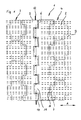
- the drying screen 1 shown in Figure 1 is made of a Plenty of cruciform flat bodies - exemplary designated with 2 - composed.
- the cutout too seeing flat body 2 each form transverse rows 3, 4 of Flat bodies arranged next to one another in the transverse direction 2, the following each in the longitudinal direction (arrow A) Rows are omitted.
- the following transverse rows are compared to the transverse rows 3, 4 shown half the width of the flat body 2 offset, so that this Rows in the shown transverse rows 3, 4 like a puzzle in border the way, as in the example according to FIG 2 can be seen.
- transverse rows 3, 4 are two end strips 5, 6 provided that extends across the entire width of the dryer fabric 1 extend.
- the neighboring rows 3, 4 Edges of the end strips 5, 6 are serrated so that they are on the shape of the flat body 2 are adapted, namely in such a way that the protruding in the longitudinal direction Crosspieces - designated by way of example at 7 - in recesses, for example designated 8 - in the end strips 5, 6 mounting.
- connecting strands - designated by way of example with 9 - firmly anchored, by inserting them into appropriate holes and then pressed or glued.
- the connecting strands 9 each form pairs and run parallel in Longitudinal direction (arrow A).
- the connecting strands 9 extend from end bar 5 to end bar 6 over the entire length Length of the dryer fabric 1 and enforce it in the band plane extending through holes in the Flat bodies 2, namely 8 connecting strands for each flat body 2 9.
- the end strips 5, 6 each have eyelet webs - for example denoted by 10, 11 - which in the transverse direction are so offset from each other that they are in the shown overlap when coupled.
- the Eyelet webs 10, 11 have transversely extending Through holes that are aligned when coupled and are penetrated by a coupling plug wire 12. About this coupling plug wire 12 are the ends of the Dryer screen 1 coupled.
- the thickness of the end strips 5, 6 the same in all areas, i. H. also the eyelets 10, 11 have the same thickness as the other areas the end strips 5, 6.
- Figure 2 shows a section of another dryer fabric 13. It differs from the dryer fabric 1 according to the figure 1 only in that they are also cruciform here trained flat body - designated 14 by way of example - in the middle in the transverse direction of the dryer fabric 13 extending flexible joint - exemplary with 15 designated - have.
- the flexibility in the area of the flexible joint 15 can be by appropriate Reduction in the thickness of the flat body 14 in this Area can be effected. Because there are no tractive forces on the Flat body 14 act, rather this from the connecting strands - designated by way of example at 16 - added have, this weakening of the flat body 14th no influence on the tensile strength of the dryer fabric 13.
- Dryer screen 17 does not have - as in the exemplary embodiments according to Figures 1 and 2 - cruciform, but hexagonal flat body - designated 18 by way of example -, These flat bodies 18 are arranged so that two of their edges are transverse to the longitudinal direction Extend (arrow A).
- the flat bodies 18 are also here arranged like a puzzle, so that there are gaps between them - exemplified with 19 - result that everywhere have the same width. Is adapted accordingly an end bar 20 with eyelets - for example with 21 designated - is provided. You can therefore in the same Way as in the exemplary embodiment according to FIG. 1 with a complementarily designed end bar on the other End of the dryer fabric 17 are coupled.
- connecting strands are anchored in the end bar 20 - designated by way of example at 22 - that from the end bar 20 shown here to the other, Extend end bar, not shown.
- everyone Flat body 18 is on 5 of these connecting strands 20th pressed on, so firmly connected to them.
- the embodiment shown in Figure 4 Dryer screen 25 is also made of regular hexagonal Flat bodies - designated by way of example at 26 - constructed.
- the flat bodies 26 are, however, opposite the embodiment shown in Figure 3 rotated by 30 °, so that each two opposite edges in The longitudinal direction (arrow A) of the dryer fabric 25 runs.
- To each of the two edges of the dryer fabric 25 is the density of the connecting strands - exemplary designated by 28 - increased to special in this area to ensure good transverse stability.
- the trapezoidal edge flat body 27th are each penetrated by two connecting strands 28, which secures them against tipping around their longitudinal axis.
- the Connecting strands 28 are also in an end bar here 29 anchored, which one at its free end straight end, but in the same way with eyelets can be provided as in the previously described Embodiments.
- FIG 5 is another embodiment of a Dryer screen 30 shown, namely one end portion.
- the dryer fabric 30 is made of rectangular, rod-like Flat bodies - labeled 31 and 32, for example - Assembled, the flat bodies 31, 32 transverse rows 33, 34, 35 form.
- Each transverse row is 33, 34, 35 made of long flat bodies - designated 31 by way of example -
- the flat bodies are in each transverse row 33, 34, 35 31, 32 arranged differently, with between the flat bodies 31, 32 each in a transverse row 33, 34, 35 gaps - identified by way of example at 36 - result.
- the flat bodies 31, 32 are distributed so that the gaps 36 in a transverse row 33, 34, 35 at least in an adjacent transverse row 33, 34, 35 of a flat body 31, 32 is bridged. Because the short flat body 32 of four connecting strands - designated 37 by way of example - And the long flat body 31 of eight connecting strands 37 are enforced, this results a kind of networking of the flat bodies 31, 32 with one another and thus a cross stabilization to each other.
- the connecting strands 37 are again in one End bar 38 with eyelet webs - designated 39 by way of example - anchored.
- the end bar 38 can be the same Way as in the embodiments according to the figures 1 to 3 with a complementary end bar at the other end of the dryer fabric 30 are coupled.
- Figures 6 to 13 show cross-shaped flat bodies same size, all of which are labeled 40. she differ in that they have different geometric Forming through holes - exemplary with Designated 41 - have.
- the flat body 40 has circular through holes 41 of the same diameter.
- the flat body 40 according to FIG. 7 has round, triangular, trapezoidal, square, parallelogram-like and octagonal through holes 41.
- rectangular through holes 41 in a parallel arrangement intended.
- the embodiment 10 has rectangular through holes 41 in a parallel arrangement, centered a rectangular through hole 41 transverse thereto is provided.
- the flat body 40 has pentagonal Through holes 41 and square in Figure 12 Through holes 41 in a regular distribution.
- the embodiment 13 contains star-shaped Through holes 41.
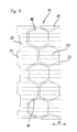
- FIG. 14 shows a further, cross-shaped flat body 42 shown in perspective. It consists of two complementary ones Flat body halves 43, 44 that are spaced apart are shown and facing each other Side half-channels - labeled 45 and 46, for example - exhibit.
- the lower flat body half 44 has four coupling pins 47, 48, 49, 50 on that of the upper half of the flat body 43 stand vertically on the facing side.
- the upper flat body half 43 has - which can not be seen here is - matching mounting holes, with the coupling pins 47, 48, 49, 50 and the mounting holes so are designed so that both lock together when the Flat body halves 43, 44 are placed one on top of the other.
- the flat body halves are used to mount the flat body 42 43, 44 from both sides to those not shown here Line wires laid out so that they are included in the Half channels 45, 46 can be found.
- the flat body halves 43, 44 complement the half channels 45, 46 to the full channels receiving the longitudinal wires, the coupling pins 47, 48, 49, 50 and the receiving bores for a firm hold of the flat body 42 the longitudinal wires due to friction.
Abstract
Description
Die Erfindung betrifft ein Entwässerungsband, insbesondere als Trockensieb für Papiermaschinen, welche aus einer Vielzahl von plättchenförmigen Flachkörpern zusammengesetzt ist, die zur Einstellung der Durchlässigkeit Durchgangsöffnungen aufweisen und/oder zwischen sich Lücken freilassen, wobei die Flachkörper über biegsame Verbindungsstränge, die die Flachkörper durchdringen, untereinander derart gekuppelt sind, daß die im Betrieb auf das Entwässerungsband wirkenden Längskräfte auf sie einwirken.The invention relates to a drainage belt, in particular as a dryer for paper machines, which from a Variety of platelet-shaped flat bodies composed is used to adjust the permeability through openings have and / or gaps between them leave blank, the flat body over flexible connecting strands, that penetrate the flat bodies, among themselves are coupled so that in operation on the Longitudinal forces acting on the drainage tape act on them.
Ein solches Entwässerungsband ist der DE 37 35 709 A1 zu entnehmen. Bei diesem Entwässerungsband sind eine Vielzahl von Flachkörpern vorgesehen, welche als längliche, sich in Querrichtung erstreckende Flachleisten ausgebildet sind, die in Längsrichtung des Entwässerungsbands hintereinander angeordnet und durch quer verlaufende Steckdrähte miteinander gekuppelt sind. Hierzu greifen die Flachkörper wechselweise ineinander, so daß fluchtende Durchgangskanäle entstehen, in die die Steckdrähte eingeschoben werden können. Such a drainage belt is DE 37 35 709 A1 remove. There are a lot of this drainage belt provided by flat bodies, which as elongated, flat strips extending in the transverse direction are in the longitudinal direction of the drainage belt arranged one behind the other and by transverse Plug wires are coupled together. Use this the flat bodies alternate with each other, so that aligned Through channels arise in which the plug wires can be inserted.
Ein solches Entwässerungsband hat erhebliche Vorteile. Die plättchenförmigen Flachkörper können auf einfache und schnelle Weise im Spritzguß oder mittels Extrudierverfahren hergestellt werden. Durch ihre Kombination lassen sich Entwässerungsbänder in nahezu beliebiger Länge und Breite anfertigen. Die Durchlässigkeit in Dickenrichtung kann mit Hilfe definierter Durchgangsöffnungen in den Flachkörpern selbst und/oder durch Vorsehen von Lücken zwischen den Flachkörpern präzise und reproduzierbar an die jeweiligen Anforderungen angepaßt werden. Trotz dieser Durchgangsöffnungen und/oder Lücken findet die Papierbahn eine großflächige Abstützung, so daß praktisch keine Markierungen der Papierbahn entstehen. Auch bezüglich der Dicke der Flachkörper besteht große Freiheit, d. h. sie kann den jeweiligen maschinellen Anforderungen angepaßt werden. Entsprechende Freiheit besteht bei der Wahl des Materials für die Flachkörper. Hierfür kommen Kunststoffe, wie Thermoplaste, Duroplaste und Gießharze, in Frage. Die Flachkörper können jedoch auch aus Elastomeren oder sogar Metallen hergestellt werden. Dabei ist auch denkbar, daß nicht alle Flachkörper eines Entwässerungsbands aus demselben Material hergestellt werden, so daß verschiedene Materialien im Wechsel vorgesehen werden können.Such a drainage belt has considerable advantages. The platelet-shaped flat body can be easily and quickly by injection molding or by extrusion getting produced. Let through their combination drainage tapes of almost any length and Make width. Permeability in the thickness direction can be placed in the Flat bodies themselves and / or by providing gaps between the flat bodies precisely and reproducibly the respective requirements are adjusted. Despite this The paper web finds through openings and / or gaps a large-area support, so practical there are no marks on the paper web. Also regarding the thickness of the flat body gives great freedom d. H. it can meet the respective machine requirements be adjusted. Corresponding freedom exists with the Choice of material for the flat body. Come for this Plastics, such as thermoplastics, thermosets and casting resins, in question. However, the flat bodies can also be made of elastomers or even metals. It is also conceivable that not all flat bodies of a drainage belt be made from the same material, so that different materials are provided alternately can.
Bei der Entwicklung dieser Art von Entwässerungsbändern hat sich herausgestellt, daß eine für alle Einsatzzwecke ausreichende Zugfestigkeit nicht erreicht werden konnte, insbesondere wenn die Flachkörper aus Kunststoff hergestellt werden. Selbst Verstärkungen der spritzgegossenen Flachkörper durch Glasfasern o. dgl. halfen wenig.When developing this type of drainage tapes has been found to be one for all uses sufficient tensile strength could not be achieved, especially if the flat body is made of plastic become. Even reinforcements of the injection molded Flat bodies through glass fibers or the like helped little.
Der Erfindung liegt somit die Aufgabe zugrunde, ein Entwässerungsband der eingangs genannten Art so auszubilden, daß es für die Aufnahme hoher Zugkräfte in Längsrichtung des Entwässerungsbands geeignet ist.The invention is therefore based on the object of a drainage belt of the type mentioned at the beginning that it is capable of absorbing high longitudinal tensile forces of the drainage belt is suitable.
Diese Aufgabe wird erfindungsgemäß dadurch gelöst, daß die Verbindungsstränge sich in Längsrichtung der Papiermaschinenbespannung erstrecken und mit ihren Enden in Endstücken verankert sind, welche miteinander kuppelbar sind. Grundgedanke der Erfindung ist es folglich, die auf das Entwässerungsband im Betrieb einsetzenden Längskräfte durch sich in Längsrichtung erstreckende Verbindungsstränge aufzunehmen. Es hat sich gezeigt, daß hierdurch wesentlich höhere Längskräfte als bei dem Entwässerungsband nach dem Stand der Technik aufgenommen werden können, wobei durch entsprechende Wahl der Art, des Querschnitts und des Materials der Verbindungsstränge eine Anpassung an die jeweiligen Erfordernisse möglich ist.This object is achieved in that the connecting strands extend in the longitudinal direction of the paper machine clothing extend and with their ends in End pieces are anchored, which can be coupled together are. The basic idea of the invention is therefore based on the longitudinal forces used during operation through connecting strands extending in the longitudinal direction to record. It has been shown that this much higher longitudinal forces than with the drainage belt can be recorded according to the state of the art, by appropriate choice of type, cross-section and the material of the connecting strands Adaptation to the respective requirements is possible.
Die Verbindungsstränge können beispielsweise als Monofilamente, monofile Zwirne, ungedrehte Bündel von Monofilen, flachen oder ovalen Bändchen o. dgl. ausgebildet sein, wobei diese Art Verbindungsstränge auch geflochten, gewebt oder gewirkt sein können. Sie können auch beschichtet sein. Als Materialien kommen insbesondere PET, PPS, PEK, PEEK, Polysulfon, PEN, thermoplastisches aromatisches PA und auch Stahl in Frage. Grundsätzlich sollten die Verbindungsstränge thermisch und chemisch mindestens so belastbar sein wie die Flachkörper selbst.The connecting strands can, for example, as monofilaments, monofilament threads, untwisted bundles of monofilaments, flat or oval ribbons or the like be, with this type of connecting strands also braided, can be woven or knitted. They can also be coated his. In particular PET, PPS, PEK, PEEK, polysulfone, PEN, thermoplastic aromatic PA and also steel in question. Basically, should the connecting strands at least thermally and chemically be as resilient as the flat body itself.
Die Verankerung der Verbindungsstränge in den Endstücken kann auf verschiedene Weise geschehen, beispielsweise durch Verschweißen, Verkleben, Verpressen oder auch durch Umschlingung. Die Endstücke können als Einzelstücke ausgebildet sein, in die nur ein Verbindungsstrang oder wenige davon verankert sind. Sie können aber auch als Endleisten ausgebildet sein, in die eine Vielzahl von Verbindungssträngen verankert sind, wobei die Endleisten sich auch über die gesamte Breite des Entwässerungsbands erstrecken können. Über die Endstücke kann das Entwässerungsband auf einfache Weise geschlossen werden. In diesem Zustand bilden jeweils zwei Endstücke eine Naht.Anchoring the connecting strands in the end pieces can be done in different ways, for example by welding, gluing, pressing or also by Wrapping. The end pieces can be designed as individual pieces be in which only a connecting strand or a few of which are anchored. But you can also use them as end strips be formed in which a plurality of connecting strands are anchored, the end strips also across the entire width of the drainage belt can extend. The drainage belt can be placed over the end pieces be closed in a simple manner. In this Condition, two end pieces form a seam.
Grundsätzlich besteht die Möglichkeit, ein Entwässerungsband aus einer Mehrzahl von Teilstücken zusammenzusetzen, wobei jedes Teilstück stirnseitig Endstücke aufweist, die mit Endstücken des nachfolgenden Teilstücks gekuppelt werden. Im allgemeinen wird man jedoch die Verbindungsstränge sich über die gesamte Länge des Entwässerungsbands erstrecken lassen, so daß nur eine Naht entsteht.Basically there is the possibility of a drainage belt to be composed of a plurality of sections, wherein each section has end pieces on the end faces that coupled with end pieces of the following section become. In general, however, one becomes the connecting strands along the entire length of the drainage belt let it extend so that only one seam is created.
In weiterer Ausgestaltung der Erfindung ist vorgesehen, daß die Flachkörper von zumindest zwei Verbindungssträngen durchsetzt sind, damit sie einwandfrei in der Bandebene geführt sind und nicht kippen können. Vorzugsweise sollten die Flachkörper zueinander versetzte Querreihen bilden, wobei Verbindungsstränge derart verlaufen, daß sie zueinander versetzte Flachkörper benachbarter Querreihen durchsetzen. Diese Art Vernetzung gibt dem Entwässerungsband insbesondere in Querrichtung Stabilität.In a further embodiment of the invention, that the flat body of at least two connecting strands are enforced so that they are perfectly in the band level are guided and cannot tip over. Preferably the flat bodies should have staggered transverse rows form, connecting strands run such that flat bodies of adjacent transverse rows offset from one another push through. This type of networking gives the drainage belt stability in the transverse direction in particular.
Die Flachkörper können in ihrer geometrischen Umrißgestaltung weitgehend frei ausgebildet sein. Grundsätzlich sollten sie geometrische Formen haben, die sich puzzleartig ergänzen, wobei die Flachkörper untereinander identisch sein können, aber nicht müssen. Hierfür kommen insbesondere Rechtecke, aber auch Vielecke, z. B. regelmäßige Sechsecke oder kreuzförmige Flachkörper in Frage, die gerundete Ecken haben können.The flat body can in their geometric outline design be largely free. Basically they should have geometric shapes that are puzzle-like complete, the flat bodies being identical to one another can be, but need not be. For this come in particular Rectangles, but also polygons, e.g. B. regular Hexagons or cross-shaped flat bodies in question that can have rounded corners.
Abweichend von den vorbeschriebenen Geometrien können die Flachkörper auch als Flachstäbe ausgebildet sein, von denen jeweils mehrere in Querrichtung des Entwässerungsbands nebeneinander unter Bildung einer Querreihe angeordnet sind, wobei die Flachstäbe zweier benachbarter Querreihen so angeordnet sind, daß die Lücken der einen Querreihe von Flachstäben der anderen Querreihe überbrückt werden.Deviating from the geometries described above, the Flat body can also be designed as flat bars, of which several each in the transverse direction of the drainage belt arranged side by side to form a transverse row are, the flat bars of two adjacent Cross rows are arranged so that the gaps of one Cross row bridged by flat bars of the other cross row become.
Das Material für die Flachkörper sollte wie das der Verbindungsstränge den jeweiligen Anforderungen angepaßt sein. Bei einer Anwendung als Trockensieb kommen insbesondere warmefeste Materialien wie PET, PPS, PEK, PEEK, Polysulfon, PEN, thermoplastisches aromatisches PA sowie Metalle wie Stahl oder Leichtmetall in Frage. Soweit Kunststoffe eingesetzt werden, können die Flachkörper im Spritzgußverfahren hergestellt werden. The material for the flat body should be like that of the connecting strands adapted to the respective requirements his. When used as a dryer fabric come in particular heat-resistant materials such as PET, PPS, PEK, PEEK, Polysulfone, PEN, thermoplastic aromatic PA as well Metals like steel or light metal in question. So far Plastics are used, the flat body in Injection molding processes are manufactured.
Im übrigen können die Flachkörper auch Gestaltungen aufweisen,
wie sie schon in der DE-37 35 709 A1 beschrieben
sind, d. h. sie können sich auch über die gesamte Breite
des Entwässerungsbands erstrecken und/oder als Hohlkörper
ausgebildet sein, um Material und damit Gewicht einzusparen.
Dabei muß die Hohlkörperausbildung nicht geschlossen
sein und kann beispielsweise so gestaltet sein, daß die
Hohlräume untereinander in Bandquer- und/oder in Bandlängsrichtung
in Verbindung zueinander stehen. In diese
Hohlräume können gewünschte Materialien eingelagert werden.
Auch können die Flachkörper aus einem steifen Innenträgerteil
und einem dieses umgebenden Kunststoffaußenmantel
bestehen, also schichtenförmig ausgebildet sein.
Dabei können auch für die Außen- und Innenseite des Entwässerungsbands
unterschiedliche Materialien vorgesehen
sein. Daneben können auch aufkaschierte oder aufgedampfte
Folien vorgesehen sein, um beispielsweise Wärmestrahlung
zu reflektieren. Desweiteren können Beflockungen oder eine
Beschichtung mit Schaumstoff oder Faservlies vorgenommen
werden.Otherwise, the flat bodies can also have designs
as already described in
Grundsätzlich besteht die Möglichkeit, die Flachkörper lose auf die Verbindungsstränge aufzureihen, wobei die Verbindungsstränge entsprechende Durchgangslöcher in den Flachkörpern durchsetzen. Sie können aber auch mit den Verbindungssträngen verbunden sein, beispielsweise verklebt oder heiß oder kalt verpreßt sein. Basically, there is the possibility of the flat body string loosely on the connecting strands, the Corresponding through holes in the Push through flat bodies. You can also use the Connecting strands connected, for example glued or hot or cold pressed.
Nach einem weiteren Merkmal der Erfindung ist vorgesehen, daß die Flachkörper in Querrichtung des Entwässerungsbands Biegescharniere aufweisen, damit sie sich besser an Umlenkwalzen anpassen können, insbesondere wenn sie relativ großflächig ausgebildet sind. Ein Flachkörper kann auch mehrere solcher Biegescharniere aufweisen. Die Biegescharniere können durch entsprechende Schwächung des Materialquerschnitts gebildet werden.According to a further feature of the invention, that the flat body in the transverse direction of the drainage belt Have bending hinges so that they fit better Deflection rollers can adjust, especially if they are relative are formed over a large area. A flat body can also have several such hinges. The bending hinges can be weakened accordingly Material cross section are formed.
Ferner ist gemäß der Erfindung vorgesehen, daß die Endstücke ösenartige Durchgangskanäle aufweisen, durch die in fluchtender Stellung ein Kupplungsdraht einsteckbar ist.It is further provided according to the invention that the end pieces have eyelet-like through-channels through which A coupling wire can be inserted in the aligned position is.
Nach der Erfindung ist desweiteren vorgeschlagen, daß die Endstücke durchströmbare Durchgangsöffnungen aufweisen, um die Durchlässigkeit des Entwässerungsbands insbesondere für Dampf im Bereich der Endstücke an die in den übrigen Bereichen anzupassen, wo die Durchlässigkeit aufgrund von Durchgangsöffnungen in den Flachkörpern und/oder mittels Lücken zwischen diesen gesteuert wird.According to the invention it is further proposed that the Have end pieces through which through-openings can flow, the permeability of the drainage tape in particular for steam in the area of the end pieces to that in the rest Adjust areas where permeability is due of through openings in the flat bodies and / or by means of Gaps between these are controlled.
Die Erfindung sieht schließlich vor, daß Endstücke und/oder Flachkörper aus zwei komplementären Hälften zusammengesetzt sind, die die Verbindungsstränge zwischen sich einschließen. Hierzu sollten die Hälften an den einander zugewandten Seiten Halbkanäle für die Aufnahme der Verbindungsstränge aufweisen. Die Hälften werden auf beiden Seiten der Verbindungsstränge angesetzt und dann miteinander verbunden. Die Verbindung kann mittels Klebstoff oder Heißversiegelung geschehen. Es können jedoch auch Kupplungselemente vorgesehen sein, die ineinandergreifen und dabei verrasten.Finally, the invention provides that end pieces and / or flat body composed of two complementary halves are the connecting strands between to lock myself in. To do this, the halves should face each other facing sides half channels for receiving the Have connecting strands. The halves are on both Attach the sides of the connecting strands and then together connected. The connection can be made using adhesive or heat sealing happen. However, it can also Coupling elements can be provided which interlock and lock in place.
In der Zeichnung ist die Erfindung anhand von Ausführungsbeispielen näher veranschaulicht. Es zeigen:
Figur 1- eine Draufsicht auf den Nahtbereich eines Trockensiebs gemäß der Erfindung;
Figur 2- eine Draufsicht auf einen Ausschnitt eines weiteren Trockensiebs mit Flachkörpern, die Biegescharniere aufweisen;
Figur 3- eine Draufsicht auf einen Endbereich eines dritten Trockensiebs gemäß der Erfindung;
- Figur 4
- eine Draufsicht auf den Endbereich eines vierten Trockensiebs;
Figur 5- eine Draufsicht auf den Endbereich eines fünften Trockensiebs;
Figuren 6bis 13- verschiedene Beispiele von kreuzförmigen Flachkörpern mit Durchgangsöffnungen und
Figur 14- einen zweiteiligen Flachkörper.
- Figure 1
- a plan view of the seam area of a dryer fabric according to the invention;
- Figure 2
- a plan view of a section of a further dryer fabric with flat bodies that have bending hinges;
- Figure 3
- a plan view of an end portion of a third dryer fabric according to the invention;
- Figure 4
- a plan view of the end portion of a fourth dryer fabric;
- Figure 5
- a plan view of the end portion of a fifth dryer fabric;
- Figures 6 to 13
- different examples of cross-shaped flat bodies with through openings and
- Figure 14
- a two-part flat body.
Das in Figur 1 dargestellte Trockensieb 1 ist aus einer
Vielzahl von kreuzförmigen Flachkörpern - beispielhaft
mit 2 bezeichnet - zusammengesetzt. Die im Ausschnitt zu
sehenden Flachkörper 2 bilden jeweils Querreihen 3, 4 von
in Querrichtung nebeneinander angeordneten Flachkörpern
2, wobei die jeweils in Längsrichtung (Pfeil A) nachfolgenden
Reihen weggelassen sind. Die nachfolgenden Querreihen
sind gegenüber den gezeigten Querreihen 3, 4 um
die halbe Breite der Flachkörper 2 versetzt, so daß diese
Reihen in die gezeigten Querreihen 3, 4 puzzleartig in
der Weise einfassen, wie dies in dem Beispiel gemäß Figur
2 zu sehen ist.The
Zwischen den Querreihen 3, 4 sind zwei Endleisten 5, 6
vorgesehen, die sich über die gesamte Breite des Trockensiebs
1 erstrecken. Die den Querreihen 3, 4 benachbarten
Kanten der Endleisten 5, 6 sind so gezahnt, daß sie an
die Formgebung der Flachkörper 2 angepaßt sind, und zwar
in der Weise, daß die in Längsrichtung vorspringenden
Stege - beispielhaft mit 7 bezeichnet - in Ausnehmungen-beispielhaft
mit 8 bezeichnet - in den Endleisten 5, 6
einfassen.Between the
In den Endleisten 5, 6 sind die Enden von 32 Verbindungssträngen
- beispielhaft mit 9 bezeichnet - fest verankert,
indem sie in entsprechende Löcher eingesetzt und
dann verpreßt oder verklebt worden sind. Die Verbindungsstränge
9 bilden jeweils Paare und verlaufen parallel in
Längsrichtung (Pfeil A). Die Verbindungsstränge 9 erstrecken
sich von Endleiste 5 zu Endleiste 6 über die gesamte
Länge des Trockensiebs 1 und durchsetzen dabei in
der Bandebene sich erstreckende Durchgangslöcher in den
Flachkörpern 2, und zwar pro Flachkörper 2 jeweils 8 Verbindungsstränge
9. Aufgrund der Versetzung der Flachkörper
2 verläuft der Teil der Verbindungsstränge 9, der in
den dargestellten Reihen 3, 4 den Mittenbereich der
Flachkörper 2 durchsetzt, in den hier nicht sichtbaren
Flachkörpern der jeweils darauffolgenden Reihen durch deren
Randstege, während umgekehrt die in den dargestellten
Reihen 3, 4 durch die Randstege der Flachkörper 2 gehenden
Verbindungsstränge 9 die Mittenbereich der Flachkörper
2 der hier nicht sichtbaren, folgenden Flachkörper
durchsetzen.In the end strips 5, 6 are the ends of 32 connecting strands
- designated by way of example with 9 - firmly anchored,
by inserting them into appropriate holes and
then pressed or glued. The connecting strands
9 each form pairs and run parallel in
Longitudinal direction (arrow A). The connecting strands 9 extend
from
Die Endleisten 5, 6 weisen jeweils Ösenstege - beispielhaft
mit 10, 11 bezeichnet - auf, welche in Querrichtung
so gegeneinander versetzt sind, daß sie sich in dem gezeigten
gekuppelten Zustand zahnartig überlappen. Die
Ösenstege 10, 11 weisen in Querrichtung verlaufende
Durchgangslöcher auf, die in gekuppeltem Zustand fluchten
und von einem Kupplungssteckdraht 12 durchsetzt sind.
Über diesen Kupplungssteckdraht 12 sind die Enden des
Trockensiebs 1 gekuppelt. Dabei ist die Dicke der Endleisten
5, 6 in allen Bereichen gleich, d. h. auch die Ösenstege
10, 11 haben die gleiche Dicke wie die übrigen Bereiche
der Endleisten 5, 6.The end strips 5, 6 each have eyelet webs - for example
denoted by 10, 11 - which in the transverse direction
are so offset from each other that they are in the shown
overlap when coupled. The
Figur 2 zeigt einen Ausschnitt eines anderen Trockensiebs
13. Es unterscheidet sich von dem Trockensieb 1 gemäß Figur
1 lediglich dadurch, daß die hier ebenfalls kreuzförmig
ausgebildeten Flachkörper - beispielhaft mit 14 bezeichnet
- mittig ein sich in Querrichtung des Trockensiebs
13 erstreckendes Biegegelenk - beispielhaft mit 15
bezeichnet - aufweisen. Dies macht das Trockensieb 13
beim Umschlingen von Walzen anschmiegsamer. Die Biegsamkeit
im Bereich des Biegegelenks 15 kann durch entsprechende
Verringerung der Dicke des Flachkörpers 14 in diesem
Bereich bewirkt werden. Da keine Zugkräfte auf die
Flachkörper 14 wirken, vielmehr diese von den Verbindungssträngen
- beispielhaft mit 16 bezeichnet - aufgenommen
werden, hat diese Schwächung der Flachkörper 14
auf die Zugfestigkeit des Trockensiebs 13 keinen Einfluß.Figure 2 shows a section of another
Das in Figur 3 dargestellte Ausführungsbeispiel eines
Trockensiebs 17 hat nicht - wie bei den Ausführungsbeispielen
gemäß den Figuren 1 und 2 - kreuzförmige, sondern
sechseckige Flachkörper - beispielhaft mit 18 bezeichnet
- , wobei diese Flachkörper 18 so angeordnet sind,
daß sich jeweils zwei ihrer Kanten quer zur Längsrichtung
(Pfeil A) erstrecken. Auch hier sind die Flachkörper 18
puzzleartig angeordnet, so daß sich zwischen ihnen Lücken
- beispielhaft mit 19 bezeichnet - ergeben, die überall
die gleiche Breite haben. Entsprechend angepaßt ist auch
eine Endleiste 20, die mit Ösenstegen - beispielhaft mit
21 bezeichnet - versehen ist. Sie kann deshalb in gleicher
Weise wie bei dem Ausführungsbeispiel gemäß Figur 1
mit einer komplementär ausgebildeten Endleiste am anderen
Ende des Trockensiebs 17 gekuppelt werden.The embodiment shown in Figure 3
In der Endleiste 20 verankert sind die Enden von Verbindungssträngen
- beispielhaft mit 22 bezeichnet -, die
sich von der hier gezeigten Endleiste 20 bis zu der anderen,
nicht dargestellten Endleiste erstrecken. Jeder
Flachkörper 18 ist auf 5 dieser Verbindungsstränge 20
aufgepreßt, also fest mit diesen verbunden. Jeweils einer
der Verbindungsstränge - beispielhaft mit 23 bezeichnet-durchsetzt
den Randbereich auf einer Seite eines Flachkörpers
18 und anschließend den Randbereich auf der anderen
Seite eines nachfolgenden, quer versetzt zu dem einen
angeordneten Flachkörper 18. Auf diese Weise ist die Zuordnung
der Flachkörper 18 in Querrichtung stabilisiert.The ends of connecting strands are anchored in the end bar 20
- designated by way of example at 22 - that
from the
An den beiden Rändern des Trockensiebs 17 sind zu deren
Begradigung passende, dreiecksförmige Flachkörper - beispielhaft
mit 24 bezeichnet - vorgesehen. Auch sie werden
durch Verbindungsstränge 23 durchsetzt. Es versteht sich,
daß solche randseitigen, Lücken ausfüllenden Flachkörper
24 auch bei den Ausführungsbeispielen gemäß den Figuren 1
und 2 vorgesehen sein können.At the two edges of the
Das in Figur 4 dargestellte Ausführungsbeispiel eines
Trockensiebs 25 ist ebenfalls aus regelmäßig sechseckigen
Flachkörpern - beispielhaft mit 26 bezeichnet - aufgebaut.
Die Flachkörper 26 sind allerdings hier gegenüber
dem Ausführungsbeispiel gemäß Figur 3 um 30° verdreht angeordnet,
so daß jeweils zwei gegenüberliegende Kanten in
Längsrichtung (Pfeil A) des Trockensiebs 25 verlaufen.
Auch hier sind randseitige Flachkörper - beispielhaft mit
27 bezeichnet - vorgesehen, die für einen geraden Randabschluß
sorgen und die dort vorhandenen Lücken passend
ausfüllen. Jeweils zu den beiden Rändern des Trockensiebs
25 ist die Dichte der Verbindungsstränge - beispielhaft
mit 28 bezeichnet - erhöht, um in diesem Bereich für besonders
gute Querstabilität zu sorgen. Dies hat auch zur
Folge, daß die trapezförmigen randseitigen Flachkörper 27
jeweils von zwei Verbindungssträngen 28 durchsetzt werden,
was sie gegen Kippen um ihre Längsachse sichert. Die
Verbindungsstränge 28 sind hier ebenfalls in einer Endleiste
29 verankert, welche an ihrem freien Ende einen
geraden Abschluß hat, jedoch in gleicher Weise mit Ösenstegen
versehen sein kann wie bei den vorbeschriebenen
Ausführungsbeispielen.The embodiment shown in Figure 4
In Figur 5 ist ein weiteres Ausführungsbeispiel eines
Trockensiebs 30 dargestellt, und zwar dessen einer Endbereich.
Das Trockensieb 30 ist aus rechteckigen, stabartigen
Flachkörpern - beispielhaft mit 31 bzw. 32 bezeichnet
- zusammengesetzt, wobei die Flachkörper 31, 32 Querreihen
33, 34, 35 bilden. Jede Querreihe 33, 34, 35 ist
aus langen Flachkörpern - beispielhaft mit 31 bezeichnet
- und kurzen Flachkörpern - beispielhaft mit 32 bezeichnet
- so zusammengesetzt, daß sich Querreihen 33, 34, 35
gleicher Länge und gerade Seitenkanten des Trockensiebs
30 ergeben. In jeder Querreihe 33, 34, 35 sind die Flachkörper
31, 32 unterschiedlich angeordnet, wobei sich zwischen
den Flachkörpern 31, 32 in jeweils einer Querreihe
33, 34, 35 Lücken - beispielhaft mit 36 bezeichnet - ergeben.
Die Flachkörper 31, 32 sind dabei so verteilt, daß
die Lücken 36 in einer Querreihe 33, 34, 35 zumindest in
einer benachbarten Querreihe 33, 34, 35 von einem Flachkörper
31, 32 überbrückt wird. Da die kurzen Flachkörper
32 von vier Verbindungssträngen - beispielhaft mit 37 bezeichnet
- und die langen Flachkörper 31 von acht Verbindungssträngen
37 durchsetzt werden, ergibt sich hierdurch
eine Art Vernetzung der Flachkörper 31, 32 untereinander
und damit eine Querstabilisierung zueinander.In Figure 5 is another embodiment of a
Die Verbindungsstränge 37 sind auch hier wieder in einer
Endleiste 38 mit Ösenstegen - beispielhaft mit 39 bezeichnet
- verankert. Die Endleiste 38 kann in gleicher
Weise wie bei den Ausführungsbeispielen gemäß den Figuren
1 bis 3 mit einer komplementären Endleiste am anderen Ende
des Trockensiebs 30 gekuppelt werden.The connecting
Die Figuren 6 bis 13 zeigen kreuzförmige Flachkörper gleicher Größe, die sämtlich mit 40 bezeichnet sind. Sie unterscheiden sich dadurch, daß sie unterschiedliche geometrische Formen von Durchgangslöchern - beispielhaft mit 41 bezeichnet - aufweisen.Figures 6 to 13 show cross-shaped flat bodies same size, all of which are labeled 40. she differ in that they have different geometric Forming through holes - exemplary with Designated 41 - have.
In Figur 6 weist der Flachkörper 40 kreisförmige Durchgangslöcher
41 gleichen Durchmessers auf. Der Flachkörper
40 gemäß Figur 7 hat runde, dreieckige, trapezförmige,
quadratische, parallelogrammartige und achteckige Durchgangslöcher
41. Beim Flachkörper 40 gemäß Figur 8 sind
rechteckige Durchgangslöcher 41 in paralleler Anordnung
vorgesehen. Bei dem Ausführungsbeispiel gemäß Figur 9 hat
der Flachkörper 40 wieder kreisförmige Durchgangslöcher
41, jedoch mit unterschiedlichen Durchmessern. Das Ausführungsbeispiel
gemäß Figur 10 weist rechteckige Durchgangslöcher
41 in paralleler Anordnung auf, wobei mittig
ein quer dazu verlaufendes rechteckiges Durchgangsloch 41
vorgesehen ist. In Figur 11 hat der Flachkörper 40 fünfeckige
Durchgangslöcher 41 und in Figur 12 quadratische
Durchgangslöcher 41 in regelmäßiger Verteilung. Das Ausführungsbeispiel
gemäß Figur 13 enthält sternförmige
Durchgangslöcher 41.In Figure 6, the
Es versteht sich, daß zur Einstellung der Durchlässigkeit
eines Trockensiebs auch jede beliebigen anderen Ausführungsformen
und Anordnungen von Durchgangslöchern 41 in
Frage kommen, wobei die Flachkörper 40, aus denen ein
Trockensieb zusammengesetzt ist, nicht identisch ausgebildet
sein müssen, sondern unterschiedliche Arten von
Durchgangslöchern 41 aufweisen können, um die Durchlässigkeit
des Trockensiebs auch bereichsweise abweichend zu
gestalten.It is understood that to adjust the permeability
a dryer fabric also any other embodiments
and arrangements of through
In Figur 14 ist weiterer, kreuzförmiger Flachkörper 42
perspektivisch dargestellt. Er besteht aus zwei komplementären
Flachkörperhälften 43, 44, die im Abstand zueinander
dargestellt sind und auf den einander zugewandten
Seiten Halbkanäle - beispielhaft mit 45 bzw. 46 bezeichnet
- aufweisen.FIG. 14 shows a further, cross-shaped
Die untere Flachkörperhälfte 44 weist vier Kupplungsstifte
47, 48, 49, 50 auf, die von der der oberen Flachkörperhälfte
43 zugewandten Seite senkrecht hochstehen. Die
obere Flachkörperhälfte 43 weist - was hier nicht zu sehen
ist - passende Aufnahmebohrungen auf, wobei die Kupplungsstifte
47, 48, 49, 50 und die Aufnahmebohrungen so
gestaltet sind, daß beide miteinander verrasten, wenn die
Flachkörperhälften 43, 44 aufeinandergelegt werden.The lower
Zur Montage des Flachkörpers 42 werden die Flachkörperhälften
43, 44 von beiden Seiten an die hier nicht dargestellten
Längsdrähte so angelegt, daß sie Aufnahme in die
Halbkanäle 45, 46 finden können. Beim Aneinanderdrücken
der Flachkörperhälften 43, 44 ergänzen sich die Halbkanäle
45, 46 zu die Längsdrähte aufnehmenden Vollkanälen,
wobei die Kupplungsstifte 47, 48, 49, 50 und die Aufnahmebohrungen
für einen festen Halt des Flachkörpers 42 an
den Längsdrähten aufgrund von Reibschluß sorgen.The flat body halves are used to mount the
Claims (19)
Priority Applications (14)
| Application Number | Priority Date | Filing Date | Title |
|---|---|---|---|
| DE59900740T DE59900740D1 (en) | 1999-03-12 | 1999-03-12 | Drainage belt for paper machines |
| ES99104963T ES2168817T3 (en) | 1999-03-12 | 1999-03-12 | DRAINAGE TAPE AS DRYING SIZE FOR PAPER MACHINES. |
| AT99104963T ATE211785T1 (en) | 1999-03-12 | 1999-03-12 | DEWATERING BELT FOR PAPER MACHINES |
| EP99104963A EP1035251B1 (en) | 1999-03-12 | 1999-03-12 | Dewatering band for paper machines |
| PT99104963T PT1035251E (en) | 1999-03-12 | 1999-03-12 | DRAINING BAND FOR PAPER MANUFACTURING MACHINE |
| PL00338849A PL190527B1 (en) | 1999-03-12 | 2000-03-07 | Drip-type dewatering endless belt, in particular a dewatering screen |
| TR2000/00698A TR200000698A2 (en) | 1999-03-12 | 2000-03-09 | Drainage tape, especially dry sieve. |
| MYPI20000916A MY125513A (en) | 1999-03-12 | 2000-03-09 | Dewatering band for paper machines |
| BRPI0001274-2A BR0001274B1 (en) | 1999-03-12 | 2000-03-10 | drainage mat, in particular, drying sieve. |
| US09/522,907 US6402895B1 (en) | 1999-03-12 | 2000-03-10 | Dewatering belt, in particular drying screen |
| CA002300590A CA2300590C (en) | 1999-03-12 | 2000-03-10 | Dewatering belt, in particular drying screen |
| TW089104435A TW548363B (en) | 1999-03-12 | 2000-03-10 | Dewatering belt, in particular drying screen |
| KR10-2000-0012543A KR100368679B1 (en) | 1999-03-12 | 2000-03-13 | Dewatering belt, in particular drying screen |
| CN00104027A CN1102185C (en) | 1999-03-12 | 2000-03-13 | Dewatering bands, especially drying sieve |
Applications Claiming Priority (1)
| Application Number | Priority Date | Filing Date | Title |
|---|---|---|---|
| EP99104963A EP1035251B1 (en) | 1999-03-12 | 1999-03-12 | Dewatering band for paper machines |
Publications (2)
| Publication Number | Publication Date |
|---|---|
| EP1035251A1 true EP1035251A1 (en) | 2000-09-13 |
| EP1035251B1 EP1035251B1 (en) | 2002-01-09 |
Family
ID=8237754
Family Applications (1)
| Application Number | Title | Priority Date | Filing Date |
|---|---|---|---|
| EP99104963A Expired - Lifetime EP1035251B1 (en) | 1999-03-12 | 1999-03-12 | Dewatering band for paper machines |
Country Status (14)
| Country | Link |
|---|---|
| US (1) | US6402895B1 (en) |
| EP (1) | EP1035251B1 (en) |
| KR (1) | KR100368679B1 (en) |
| CN (1) | CN1102185C (en) |
| AT (1) | ATE211785T1 (en) |
| BR (1) | BR0001274B1 (en) |
| CA (1) | CA2300590C (en) |
| DE (1) | DE59900740D1 (en) |
| ES (1) | ES2168817T3 (en) |
| MY (1) | MY125513A (en) |
| PL (1) | PL190527B1 (en) |
| PT (1) | PT1035251E (en) |
| TR (1) | TR200000698A2 (en) |
| TW (1) | TW548363B (en) |
Cited By (4)
| Publication number | Priority date | Publication date | Assignee | Title |
|---|---|---|---|---|
| US6902787B2 (en) | 2001-03-19 | 2005-06-07 | Astenjohnson, Inc. | Industrial fabric with asymmetrically apertured tiles |
| US7276137B2 (en) | 2003-08-13 | 2007-10-02 | Heimbach Gmbh & Co. | Textile product having an integrated sensor for measuring pressure and temperature |
| US7279074B2 (en) | 2003-08-13 | 2007-10-09 | Heimbach Gmbh & Co. | Paper machine clothing |
| WO2012024463A3 (en) * | 2010-08-19 | 2012-06-28 | The Procter & Gamble Company | A paper product having unique physical properties |
Families Citing this family (22)
| Publication number | Priority date | Publication date | Assignee | Title |
|---|---|---|---|---|
| DE10084901T1 (en) * | 1999-08-20 | 2002-08-14 | Astenjohnson Inc | Molded modular bicomponent connector and fabric made from a variety of such bicomponent connectors |
| WO2001014634A1 (en) * | 1999-08-20 | 2001-03-01 | Astenjohnson, Inc. | Molded modular link and a fabric made from a plurality thereof |
| US7128809B2 (en) * | 2002-11-05 | 2006-10-31 | The Procter & Gamble Company | High caliper web and web-making belt for producing the same |
| US6918998B2 (en) * | 2002-11-13 | 2005-07-19 | Albany International Corp. | On-machine-seamable industrial fabric comprised of interconnected rings |
| US8840683B2 (en) * | 2003-11-19 | 2014-09-23 | Albany International Corp. | Industrial textile fabric |
| US7720461B2 (en) * | 2004-02-26 | 2010-05-18 | Research In Motion Limited | Mobile communications device with security features |
| DE102005060525A1 (en) * | 2005-12-17 | 2007-06-21 | Voith Patent Gmbh | conveyor belt |
| US10933577B2 (en) | 2015-05-01 | 2021-03-02 | The Procter & Gamble Company | Unitary deflection member for making fibrous structures having increased surface area and process for making same |
| US9938666B2 (en) | 2015-05-01 | 2018-04-10 | The Procter & Gamble Company | Unitary deflection member for making fibrous structures having increased surface area and process for making same |
| US9976261B2 (en) | 2015-05-01 | 2018-05-22 | The Procter & Gamble Company | Unitary deflection member for making fibrous structures having increased surface area and process for making same |
| WO2016205103A1 (en) | 2015-06-19 | 2016-12-22 | The Procter & Gamble Company | Seamless unitary deflection member for making fibrous structures having increased surface area |
| CA3016186C (en) | 2016-03-24 | 2020-04-14 | The Procter & Gamble Company | Unitary deflection member for making fibrous structures |
| US10676865B2 (en) * | 2016-10-27 | 2020-06-09 | The Procter & Gamble Company | Deflecting member for making fibrous structures |
| US10815618B2 (en) | 2016-10-27 | 2020-10-27 | The Procter & Gamble Company | Deflecting member for making fibrous structures |
| US10865521B2 (en) * | 2016-10-27 | 2020-12-15 | The Procter & Gamble Company | Deflecting member for making fibrous structures |
| MX2020002378A (en) | 2017-09-29 | 2020-07-13 | Kimberly Clark Co | Twill woven papermaking fabrics. |
| WO2019067692A1 (en) * | 2017-09-29 | 2019-04-04 | Kimberly-Clark Worldwide, Inc. | Woven papermaking fabric including stabilized weave providing textured contacting surface |
| AU2018339565B2 (en) | 2017-09-29 | 2024-01-04 | Kimberly-Clark Worldwide, Inc. | Woven papermaking fabric having machine and cross-machine oriented topography |
| AU2018341591B2 (en) | 2017-09-29 | 2023-11-30 | Kimberly-Clark Worldwide, Inc. | Woven papermaking fabric having converging, diverging or merging topography |
| US11396725B2 (en) | 2017-10-27 | 2022-07-26 | The Procter & Gamble Company | Deflecting member for making fibrous structures |
| CN112739861A (en) * | 2018-09-28 | 2021-04-30 | 金伯利-克拉克环球有限公司 | Woven papermaker's fabric with discrete transverse protrusions |
| WO2020068092A1 (en) * | 2018-09-28 | 2020-04-02 | Kimberly-Clark Worldwide, Inc. | Woven papermaking fabric having intersecting twill patterns |
Citations (2)
| Publication number | Priority date | Publication date | Assignee | Title |
|---|---|---|---|---|
| DE3735709A1 (en) * | 1987-10-22 | 1989-05-03 | Heimbach Gmbh Thomas Josef | Dewatering belt |
| WO1991002642A1 (en) * | 1989-08-25 | 1991-03-07 | Huyck Corporation | Molded paper clothing |
-
1999
- 1999-03-12 AT AT99104963T patent/ATE211785T1/en not_active IP Right Cessation
- 1999-03-12 PT PT99104963T patent/PT1035251E/en unknown
- 1999-03-12 DE DE59900740T patent/DE59900740D1/en not_active Expired - Lifetime
- 1999-03-12 EP EP99104963A patent/EP1035251B1/en not_active Expired - Lifetime
- 1999-03-12 ES ES99104963T patent/ES2168817T3/en not_active Expired - Lifetime
-
2000
- 2000-03-07 PL PL00338849A patent/PL190527B1/en not_active IP Right Cessation
- 2000-03-09 TR TR2000/00698A patent/TR200000698A2/en unknown
- 2000-03-09 MY MYPI20000916A patent/MY125513A/en unknown
- 2000-03-10 TW TW089104435A patent/TW548363B/en not_active IP Right Cessation
- 2000-03-10 CA CA002300590A patent/CA2300590C/en not_active Expired - Fee Related
- 2000-03-10 BR BRPI0001274-2A patent/BR0001274B1/en not_active IP Right Cessation
- 2000-03-10 US US09/522,907 patent/US6402895B1/en not_active Expired - Fee Related
- 2000-03-13 CN CN00104027A patent/CN1102185C/en not_active Expired - Fee Related
- 2000-03-13 KR KR10-2000-0012543A patent/KR100368679B1/en not_active IP Right Cessation
Patent Citations (2)
| Publication number | Priority date | Publication date | Assignee | Title |
|---|---|---|---|---|
| DE3735709A1 (en) * | 1987-10-22 | 1989-05-03 | Heimbach Gmbh Thomas Josef | Dewatering belt |
| WO1991002642A1 (en) * | 1989-08-25 | 1991-03-07 | Huyck Corporation | Molded paper clothing |
Cited By (5)
| Publication number | Priority date | Publication date | Assignee | Title |
|---|---|---|---|---|
| US6902787B2 (en) | 2001-03-19 | 2005-06-07 | Astenjohnson, Inc. | Industrial fabric with asymmetrically apertured tiles |
| US7276137B2 (en) | 2003-08-13 | 2007-10-02 | Heimbach Gmbh & Co. | Textile product having an integrated sensor for measuring pressure and temperature |
| US7279074B2 (en) | 2003-08-13 | 2007-10-09 | Heimbach Gmbh & Co. | Paper machine clothing |
| WO2012024463A3 (en) * | 2010-08-19 | 2012-06-28 | The Procter & Gamble Company | A paper product having unique physical properties |
| AU2011291954B2 (en) * | 2010-08-19 | 2014-12-04 | The Procter & Gamble Company | A paper product having unique physical properties |
Also Published As
| Publication number | Publication date |
|---|---|
| PL338849A1 (en) | 2000-09-25 |
| US6402895B1 (en) | 2002-06-11 |
| PL190527B1 (en) | 2005-12-30 |
| EP1035251B1 (en) | 2002-01-09 |
| BR0001274B1 (en) | 2009-01-13 |
| CA2300590C (en) | 2005-01-11 |
| TR200000698A3 (en) | 2000-10-23 |
| MY125513A (en) | 2006-08-30 |
| TR200000698A2 (en) | 2000-10-23 |
| KR100368679B1 (en) | 2003-01-24 |
| DE59900740D1 (en) | 2002-02-28 |
| ATE211785T1 (en) | 2002-01-15 |
| ES2168817T3 (en) | 2002-06-16 |
| TW548363B (en) | 2003-08-21 |
| CN1266924A (en) | 2000-09-20 |
| CA2300590A1 (en) | 2000-09-12 |
| PT1035251E (en) | 2002-06-28 |
| KR20000062854A (en) | 2000-10-25 |
| BR0001274A (en) | 2000-10-10 |
| CN1102185C (en) | 2003-02-26 |
Similar Documents
| Publication | Publication Date | Title |
|---|---|---|
| EP1035251B1 (en) | Dewatering band for paper machines | |
| DE3728148C2 (en) | ||
| EP0609664B1 (en) | Dryer cloth and process for making the same | |
| EP1085120B1 (en) | Band for use in machines | |
| DE3546267A1 (en) | THREE-DIMENSIONAL CONSTRUCTION ELEMENT | |
| DE19923088C1 (en) | Woven blanket for drying section of papermaking machine has paired longitudinal filaments pulled out into long and short loops at end sides for smooth surface on paper side when locked together by inserted wire | |
| EP1357223B1 (en) | Paper machine clothing and process for making the same | |
| EP1359251A1 (en) | Paper machine clothing and method for its production | |
| EP0266786B1 (en) | Spiral fabric having double spirals | |
| EP0396035A1 (en) | Belt for papier making machines | |
| EP1333120B1 (en) | Papermaker's fabric, in particular press felt | |
| DE3735709C2 (en) | Paper machine belt | |
| DE4407097C2 (en) | Textile goods and composite material made from them | |
| EP1359252B1 (en) | Paper machine clothing and method for its production | |
| DE3914534C1 (en) | ||
| EP0763623B1 (en) | Belt for papermaking machines | |
| DE3041162C2 (en) | Woven zip fastener strap | |
| EP0112432B1 (en) | Flat produce, especially a screening belt or a link belt for paper-making machines or the like | |
| CH652282A5 (en) | ZIPPER STRIPES. | |
| EP0292700B1 (en) | Spiral fabric | |
| EP1452639A1 (en) | Paper machine clothing | |
| DE2338263C2 (en) | Device for joining straps or bands | |
| DE2243047A1 (en) | FABRIC TRACK AND METHOD OF PREPARING THE SAME FOR A JOINT | |
| DE102004061226B4 (en) | Connector assembly, connector element and manufacturing method thereof | |
| DE3640940C2 (en) |
Legal Events
| Date | Code | Title | Description |
|---|---|---|---|
| PUAI | Public reference made under article 153(3) epc to a published international application that has entered the european phase |
Free format text: ORIGINAL CODE: 0009012 |
|
| 17P | Request for examination filed |
Effective date: 19991211 |
|
| AK | Designated contracting states |
Kind code of ref document: A1 Designated state(s): AT BE CH DE ES FI FR GB IT LI NL PT SE |
|
| AX | Request for extension of the european patent |
Free format text: AL;LT;LV;MK;RO;SI |
|
| AKX | Designation fees paid |
Free format text: AT BE CH DE ES FI FR GB IT LI NL PT SE |
|
| GRAG | Despatch of communication of intention to grant |
Free format text: ORIGINAL CODE: EPIDOS AGRA |
|
| 17Q | First examination report despatched |
Effective date: 20010709 |
|
| GRAG | Despatch of communication of intention to grant |
Free format text: ORIGINAL CODE: EPIDOS AGRA |
|
| GRAH | Despatch of communication of intention to grant a patent |
Free format text: ORIGINAL CODE: EPIDOS IGRA |
|
| GRAH | Despatch of communication of intention to grant a patent |
Free format text: ORIGINAL CODE: EPIDOS IGRA |
|
| GRAA | (expected) grant |
Free format text: ORIGINAL CODE: 0009210 |
|
| REG | Reference to a national code |
Ref country code: GB Ref legal event code: IF02 |
|
| AK | Designated contracting states |
Kind code of ref document: B1 Designated state(s): AT BE CH DE ES FI FR GB IT LI NL PT SE |
|
| REF | Corresponds to: |
Ref document number: 211785 Country of ref document: AT Date of ref document: 20020115 Kind code of ref document: T |
|
| REG | Reference to a national code |
Ref country code: CH Ref legal event code: EP |
|
| REF | Corresponds to: |
Ref document number: 59900740 Country of ref document: DE Date of ref document: 20020228 |
|
| GBT | Gb: translation of ep patent filed (gb section 77(6)(a)/1977) |
Effective date: 20020406 |
|
| REG | Reference to a national code |
Ref country code: ES Ref legal event code: FG2A Ref document number: 2168817 Country of ref document: ES Kind code of ref document: T3 |
|
| REG | Reference to a national code |
Ref country code: PT Ref legal event code: SC4A Free format text: AVAILABILITY OF NATIONAL TRANSLATION Effective date: 20020321 |
|
| PLBE | No opposition filed within time limit |
Free format text: ORIGINAL CODE: 0009261 |
|
| STAA | Information on the status of an ep patent application or granted ep patent |
Free format text: STATUS: NO OPPOSITION FILED WITHIN TIME LIMIT |
|
| 26N | No opposition filed | ||
| PGFP | Annual fee paid to national office [announced via postgrant information from national office to epo] |
Ref country code: PT Payment date: 20100310 Year of fee payment: 12 Ref country code: CH Payment date: 20100325 Year of fee payment: 12 |
|
| PGFP | Annual fee paid to national office [announced via postgrant information from national office to epo] |
Ref country code: IT Payment date: 20100325 Year of fee payment: 12 Ref country code: FR Payment date: 20100331 Year of fee payment: 12 |
|
| PGFP | Annual fee paid to national office [announced via postgrant information from national office to epo] |
Ref country code: AT Payment date: 20100322 Year of fee payment: 12 |
|
| PGFP | Annual fee paid to national office [announced via postgrant information from national office to epo] |
Ref country code: NL Payment date: 20100324 Year of fee payment: 12 Ref country code: BE Payment date: 20100323 Year of fee payment: 12 |
|
| REG | Reference to a national code |
Ref country code: PT Ref legal event code: MM4A Free format text: LAPSE DUE TO NON-PAYMENT OF FEES Effective date: 20110912 |
|
| BERE | Be: lapsed |
Owner name: THOMAS JOSEF *HEIMBACH G.M.B.H. & CO. Effective date: 20110331 |
|
| REG | Reference to a national code |
Ref country code: NL Ref legal event code: V1 Effective date: 20111001 |
|
| PG25 | Lapsed in a contracting state [announced via postgrant information from national office to epo] |
Ref country code: PT Free format text: LAPSE BECAUSE OF NON-PAYMENT OF DUE FEES Effective date: 20110912 |
|
| REG | Reference to a national code |
Ref country code: CH Ref legal event code: PL |
|
| PG25 | Lapsed in a contracting state [announced via postgrant information from national office to epo] |
Ref country code: AT Free format text: LAPSE BECAUSE OF NON-PAYMENT OF DUE FEES Effective date: 20110312 |
|
| REG | Reference to a national code |
Ref country code: FR Ref legal event code: ST Effective date: 20111130 |
|
| PG25 | Lapsed in a contracting state [announced via postgrant information from national office to epo] |
Ref country code: BE Free format text: LAPSE BECAUSE OF NON-PAYMENT OF DUE FEES Effective date: 20110331 |
|
| PG25 | Lapsed in a contracting state [announced via postgrant information from national office to epo] |
Ref country code: CH Free format text: LAPSE BECAUSE OF NON-PAYMENT OF DUE FEES Effective date: 20110331 Ref country code: FR Free format text: LAPSE BECAUSE OF NON-PAYMENT OF DUE FEES Effective date: 20110331 Ref country code: LI Free format text: LAPSE BECAUSE OF NON-PAYMENT OF DUE FEES Effective date: 20110331 Ref country code: NL Free format text: LAPSE BECAUSE OF NON-PAYMENT OF DUE FEES Effective date: 20111001 |
|
| PG25 | Lapsed in a contracting state [announced via postgrant information from national office to epo] |
Ref country code: IT Free format text: LAPSE BECAUSE OF NON-PAYMENT OF DUE FEES Effective date: 20110312 |
|
| PGFP | Annual fee paid to national office [announced via postgrant information from national office to epo] |
Ref country code: GB Payment date: 20120322 Year of fee payment: 14 |
|
| GBPC | Gb: european patent ceased through non-payment of renewal fee |
Effective date: 20130312 |
|
| PG25 | Lapsed in a contracting state [announced via postgrant information from national office to epo] |
Ref country code: GB Free format text: LAPSE BECAUSE OF NON-PAYMENT OF DUE FEES Effective date: 20130312 |
|
| PGFP | Annual fee paid to national office [announced via postgrant information from national office to epo] |
Ref country code: ES Payment date: 20140324 Year of fee payment: 16 |
|
| REG | Reference to a national code |
Ref country code: ES Ref legal event code: FD2A Effective date: 20160426 |
|
| PGFP | Annual fee paid to national office [announced via postgrant information from national office to epo] |
Ref country code: SE Payment date: 20160322 Year of fee payment: 18 Ref country code: FI Payment date: 20160318 Year of fee payment: 18 |
|
| PG25 | Lapsed in a contracting state [announced via postgrant information from national office to epo] |
Ref country code: ES Free format text: LAPSE BECAUSE OF NON-PAYMENT OF DUE FEES Effective date: 20150313 |
|
| PGFP | Annual fee paid to national office [announced via postgrant information from national office to epo] |
Ref country code: DE Payment date: 20170220 Year of fee payment: 19 |
|
| PG25 | Lapsed in a contracting state [announced via postgrant information from national office to epo] |
Ref country code: FI Free format text: LAPSE BECAUSE OF NON-PAYMENT OF DUE FEES Effective date: 20170312 |
|
| REG | Reference to a national code |
Ref country code: SE Ref legal event code: EUG |
|
| PG25 | Lapsed in a contracting state [announced via postgrant information from national office to epo] |
Ref country code: SE Free format text: LAPSE BECAUSE OF NON-PAYMENT OF DUE FEES Effective date: 20170313 |
|
| REG | Reference to a national code |
Ref country code: DE Ref legal event code: R119 Ref document number: 59900740 Country of ref document: DE |
|
| PG25 | Lapsed in a contracting state [announced via postgrant information from national office to epo] |
Ref country code: DE Free format text: LAPSE BECAUSE OF NON-PAYMENT OF DUE FEES Effective date: 20181002 |