EP1034885A2 - Polishing apparatus including attitude controller for turntable and/or wafer carrier - Google Patents
Polishing apparatus including attitude controller for turntable and/or wafer carrier Download PDFInfo
- Publication number
- EP1034885A2 EP1034885A2 EP00104555A EP00104555A EP1034885A2 EP 1034885 A2 EP1034885 A2 EP 1034885A2 EP 00104555 A EP00104555 A EP 00104555A EP 00104555 A EP00104555 A EP 00104555A EP 1034885 A2 EP1034885 A2 EP 1034885A2
- Authority
- EP
- European Patent Office
- Prior art keywords
- carrier
- turntable
- polishing apparatus
- attitude
- polishing
- Prior art date
- Legal status (The legal status is an assumption and is not a legal conclusion. Google has not performed a legal analysis and makes no representation as to the accuracy of the status listed.)
- Granted
Links
Images










Classifications
-
- B—PERFORMING OPERATIONS; TRANSPORTING
- B24—GRINDING; POLISHING
- B24B—MACHINES, DEVICES, OR PROCESSES FOR GRINDING OR POLISHING; DRESSING OR CONDITIONING OF ABRADING SURFACES; FEEDING OF GRINDING, POLISHING, OR LAPPING AGENTS
- B24B37/00—Lapping machines or devices; Accessories
- B24B37/11—Lapping tools
-
- B—PERFORMING OPERATIONS; TRANSPORTING
- B24—GRINDING; POLISHING
- B24B—MACHINES, DEVICES, OR PROCESSES FOR GRINDING OR POLISHING; DRESSING OR CONDITIONING OF ABRADING SURFACES; FEEDING OF GRINDING, POLISHING, OR LAPPING AGENTS
- B24B37/00—Lapping machines or devices; Accessories
- B24B37/005—Control means for lapping machines or devices
-
- B—PERFORMING OPERATIONS; TRANSPORTING
- B24—GRINDING; POLISHING
- B24B—MACHINES, DEVICES, OR PROCESSES FOR GRINDING OR POLISHING; DRESSING OR CONDITIONING OF ABRADING SURFACES; FEEDING OF GRINDING, POLISHING, OR LAPPING AGENTS
- B24B37/00—Lapping machines or devices; Accessories
- B24B37/27—Work carriers
- B24B37/30—Work carriers for single side lapping of plane surfaces
-
- B—PERFORMING OPERATIONS; TRANSPORTING
- B24—GRINDING; POLISHING
- B24B—MACHINES, DEVICES, OR PROCESSES FOR GRINDING OR POLISHING; DRESSING OR CONDITIONING OF ABRADING SURFACES; FEEDING OF GRINDING, POLISHING, OR LAPPING AGENTS
- B24B41/00—Component parts such as frames, beds, carriages, headstocks
- B24B41/06—Work supports, e.g. adjustable steadies
- B24B41/061—Work supports, e.g. adjustable steadies axially supporting turning workpieces, e.g. magnetically, pneumatically
-
- B—PERFORMING OPERATIONS; TRANSPORTING
- B24—GRINDING; POLISHING
- B24B—MACHINES, DEVICES, OR PROCESSES FOR GRINDING OR POLISHING; DRESSING OR CONDITIONING OF ABRADING SURFACES; FEEDING OF GRINDING, POLISHING, OR LAPPING AGENTS
- B24B49/00—Measuring or gauging equipment for controlling the feed movement of the grinding tool or work; Arrangements of indicating or measuring equipment, e.g. for indicating the start of the grinding operation
- B24B49/10—Measuring or gauging equipment for controlling the feed movement of the grinding tool or work; Arrangements of indicating or measuring equipment, e.g. for indicating the start of the grinding operation involving electrical means
Definitions
- the present invention relates to a polishing apparatus for polishing an article such as a semiconductor wafer surface, in particular, a polishing apparatus provided with an attitude controller for controlling an attitude of a turntable which is provided with a polished surface and/or a carrier for carrying an article to be polished and bringing it into contact with the polishing surface of the turntable.
- CMP chemical/mechanical polisher
- Fig. 26 shows such a conventional polisher for polishing a semiconductor wafer.
- the polisher includes a turntable 52 provided on its upper surface with a polishing cloth 51 and a wafer carrier 54 for holding a semiconductor wafer 53.
- the turntable and the wafer carrier are independently rotated about their axes by motors (not shown) while the wafer 53 is engaged with the polishing cloth 51 and an abrasive liquid Q is supplied through a nozzle 57 provided above the turntable.
- the polishing cloth 51 does not engage with the wafer 53 under a uniform pressure across respective engaging surfaces, the wafer fails to be polished evenly.
- the conventional polishing apparatus is provided with a universal joint comprising a ball bearing 56 between the wafer carrier 54 and a drive shaft 55 for pressing the wafer carrier 54 against the polishing cloth 51 while drivingly rotating the wafer carrier 54.
- the universal joint enables the wafer carrier 54 to tilt about the ball bearing 56 in response to inclinations in the polishing surface of the polishing cloth 51. Consequently, the polishing surface of the polishing cloth 51 and the polished surface of the wafer 53 held by the wafer carrier 54 are kept in a parallel relation with each other, whereby pressure between the wafer and the polishing cloth is kept even across the entire surface of the wafer.
- Japanese Patent Application 06198561A discloses such a universal joint.
- the rotational moment M which tends to tilt the wafer carrier will become zero and thus the wafer carrier can be kept parallel to the turntable.
- the polishing surface or upper surface of the polishing cloth on the turntable is not exactly even across its entire area which gives rise to a change in inclination of the polishing surface which is in contact with the wafer when the turntable is rotated.
- the wafer carrier tends to tilt excessively under its inertia moment resulting in unstable tilting. Consequently, the wafer is unable to be engaged with the polishing cloth under a uniform pressure.
- JP 1058308A discloses a polishing apparatus which is provided with an electromagnetic bearing including an electromagnetic thrust bearing means and an electromagnetic radial bearing means for bearing a drive shaft of a wafer carrier with an electromagnetic force, and an attitude controller for controlling the attitude of the drive shaft to keep the wafer carrier parallel to a turntable.
- the present invention aims to solve the problems 1)-3) outlined above and, specifically, to provide a polishing apparatus which includes an attitude controller for controlling an attitude of a wafer carrier and/or a turntable so that the wafer or an object to be polished can be engaged with a polishing cloth on a turntable with a uniform pressure being exerted across its entire area.
- an object of the present invention is to provide a polishing apparatus with an attitude controller for controlling an attitude of a turntable and/or a carrier for carrying an article to be polished, whereby the article is engaged with a polishing surface on the turntable under a uniform pressure thereby being polished to a very high degree of flatness.
- a polishing apparatus comprising a turntable having a polishing surface that comes into sliding contact with an object to be polished, a support for tiltably supporting the turntable, and, an attitude controller for controlling an attitude or orientation of the turntable.
- the attitude controller may control the attitude of the turntable by controlling an angle of tilting of the turntable relative to the support means by means of an electromagnetic force.
- the polishing apparatus may include a stationary frame, and the attitude controller may comprise an electromagnetic device fixedly provided on the stationary frame of the polishing apparatus, and armature means fixedly provided on the turntable and adapted to be moved by means of an electromagnetic force generated by the electromagnetic device.
- the attitude controller may comprises cylinder device means provided under the turntable and fixed to a stationary frame of the polishing apparatus and engaged with a lower surface of the turntable so that the cylinder device means controls the attitude of the turntable by extension and contraction thereof.
- a polishing apparatus comprising a turntable having a polishing surface, a carrier for holding an article to be polished in a sliding contact relation with the polishing surface, a pressing means connected to the carrier and adapted to press the carrier towards the turntable with the article engaged with the polishing surface, and an attitude controller for controlling an attitude or orientation of the carrier.
- the pressing means may be a drive shaft for drivingly rotating the wafer carrier and the polishing apparatus includes a universal joint connecting the drive shaft and the carrier in such a manner that the carrier can tilt relative to the drive shaft.
- the attitude controller may comprise an electromagnetic device fixedly provided on a frame for rotatably supporting the drive shaft and armature means fixedly provided on the carrier and adapted to be moved by means of an electromagnetic force generated by the electromagnetic device.
- the attitude controller includes sensor means for sensing the attitude or orientation of the carrier so that the attitude controller controls the attitude of the wafer in response to the sensed attitude or orientation.
- the polishing apparatus may further includes a pressing member provided radially outside the carrier and movable up and down independently of the carrier, an urging device for urging the pressing member, and a bearing for supporting the pressing member on the carrier in such a manner that the pressing member is kept stationary while allowing the carrier to rotate.
- the carrier may include a mounting member connected to the pressing means and an article holding member with a gap interposed therebetween, and the article holding member has a lower surface for holding an article to be polished and is flexible so that it can be deformed in both a concave and convex manner in a vertical direction by controlling a pressure in the gap G.
- the carrier may include a retainer ring provided on the outer periphery of the carrier to confine the article held on the lower surface of the holding member, the retainer ring is movable vertically relative to the holding member, and the carrier further includes a pressing means for pressing the retainer ring vertically against the polishing surface of the turntable.
- a polishing apparatus including both the turntable attitude controller and the carrier attitude controller as noted above.
- Fig. 1 is a vertical sectional view showing the general arrangement of a first embodiment of the polishing apparatus according to the present invention
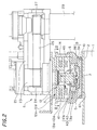
- Fig. 2 is a fragmentary sectional view showing an essential part of the polishing apparatus.
- the polishing apparatus includes a turntable 1 having a polishing cloth 2 bonded to the upper surface thereof, and a carrier apparatus 5.
- the carrier apparatus 5 includes a wafer carrier 6 for holding a semiconductor wafer 3, and a drive shaft 7 for supporting the wafer carrier 6 and applying a pressing force and rotational driving force to the wafer carrier 6.
- the carrier apparatus 5 further includes a universal coupling 8 for transmitting a pressing force from the drive shaft 7 to the wafer carrier 6 while allowing the wafer carrier to tilt relative to the drive shaft 7, and an attitude or orientation controller 11 for controlling the attitude of the wafer carrier 6.
- An abrasive liquid supply nozzle 60 is provided above the turntable 1 to supply an abrasive liquid onto the polishing cloth 2 on the turntable 1.
- the upper surface of the polishing cloth 2 constitutes a polishing surface that comes into contact with a surface of a semiconductor wafer to be polished.
- the wafer carrier 6 includes a carrier body 9 comprising a wafer holding plate 9A and a mounting plate 9B and a retainer ring 10 fixed to the outer periphery of the carrier body 9.
- the wafer carrier 6 is adapted to hold a semiconductor wafer 3 on the lower surface of the holding plate 9A in such a manner that the wafer 3 is prevented from being displaced from the lower surface of the holding plate 9A by the retaining ring 10.
- the holding plate 9A is fixedly provided on its lower surface with a resilient mat 61.
- a gap G between the holding plate 9A and the mounting plate 9B which is adapted to be subject to a fluid pressure including a vacuum.
- the holding plate 9A includes a plurality of through holes (not shown) connecting the gap G to the lower surface thereof.
- the resilient mat also includes a plurality of through holes (not shown) corresponding to the through holes of the holding plate 9A. This enables the fluid pressure to be applied to the upper surface of a wafer on the lower surface of the resilient mat 61.
- the carrier drive shaft 7 is coupled to a carrier air cylinder 22 secured to a carrier head 21.
- the carrier air cylinder 22 vertically moves the carrier drive shaft 7 thereby enabling the wafer 3 held by the carrier to be pressed against the turntable 1.
- the carrier drive shaft 7 is coupled to a rotating cylinder 23 through a key (not shown).
- the rotating cylinder 23 has a timing pulley 24 on an outer peripheral portion thereof.
- the timing pulley 24 is connected through a timing belt 25 to a timing pulley 27 provided on a carrier motor 26 secured to the carrier head 21. Accordingly, the carrier motor 26 drivingly rotates the rotating cylinder 23 and the carrier drive shaft 7 through the timing pulley 27, the timing belt 25 and the timing pulley 24, thereby drivingly rotating the carrier 6.
- the carrier head 21 is supported by a carrier head shaft 29 fixedly supported on a frame.
- the universal coupling 8 which transmits a pressing force from the carrier drive shaft 7 to the carrier 6 while allowing these members to tilt relative to each other, has a spherical bearing mechanism 40 that allows the carrier 6 and the carrier drive shaft 7 to tilt relative to each other.
- the universal coupling 8 further has a rotation transmitting mechanism 45 for transmitting the rotation of the carrier drive shaft 7 to the carrier body 9.
- the spherical bearing mechanism 40 includes a spherical recess 41a formed in the center of the lower surface of a driving flange 41 secured to the lower end of the carrier drive shaft 7.
- the spherical bearing mechanism 40 further includes a spherical recess 9a formed in the center of the upper surface of the mounting plate 9B, and a ball bearing 42 interposed between the two recesses 41a and 9a.
- the ball bearing 42 is made of a material of high hardness, such as a ceramic.
- the rotation transmitting mechanism 45 includes a driving pin (not shown) secured to the driving flange 41 and a driven pin (not shown) secured to the mounting plate 9B.
- the driven pin and the driving pin are vertically movable relative to each other. Therefore, even when the carrier body 9 tilts, the driven pin and the driving pin are kept in engagement with each other, with a point of contact shifting between them.
- the rotation transmitting mechanism 45 transmits the rotational torque of the carrier driving shaft 7 to the carrier body 9 in a reliable and stable fashion.
- Fig. 2 is a fragmentary sectional view showing an essential part of the polishing apparatus, as stated above.
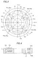
- Fig. 3 is a view as seen from the arrow III-III in Fig. 2, and
- Fig. 4 is a sectional view taken along the line IV-IV in Fig. 3.
- the attitude controller 11 includes an electromagnetic core 12 secured to the carrier head 21.
- Four magnetic poles 12a, 12b, 12c and 12d project radially outward from the electromagnetic core 12.
- Four electromagnetic coils 13a, 13b, 13c and 13d are wound on the magnetic poles 12a to 12d, respectively.
- the attitude controller 11 further includes a cylindrical armature 14 facing the magnetic poles 12a to 12d across a gap. The armature 14 is secured to the carrier body 9.
- the magnetic poles 12a to 12d each have a U-shaped sectional configuration having a 90-degree rotation.
- the upper horizontally projecting portions of the magnetic poles 12a to 12d are wound with the electromagnetic coils 13a to 13d, respectively.
- the magnetic poles 12a to 12d and the armature 14 are formed from a magnetic material, e.g. a permalloy.
- the electromagnetic coil 13a is placed at a position in positive alignment with the X-axis.
- the electromagnetic coil 13b is placed at a position in negative alignment with the X-axis.
- the electromagnetic coil 13c is placed at a position in positive alignment with the Y-axis.
- the electromagnetic coil 13d is placed at a position in negative alignment with the Y-axis.
- Four pairs of displacement sensors 15a 1 , 15a 2 ; 15b 1 , 15b 2 ; 15c 1 , 15c 2 ; and 15d 1 , 15d 2 are placed on two axes P and Q tilted at an angle of 45 degrees with respect to the X- and Y-axes.
- Each pair of displacement sensors consists of upper and lower displacement sensors.
- Each displacement sensor pair is held by a sensor holder 17.
- Fig. 5 is a block diagram showing the functional arrangement of a control part for controlling the attitude controller 11.
- the control part has a subtracter 30 and a controller 31.
- the subtracter 30 is supplied with desired values for the attitude of the carrier 6, and values ⁇ and ⁇ of displacement of a controlled system (carrier 6) that are detected by sensors 15 (displacement sensors 15a 1 , 15a 2 ; 15b 1 , 15b 2 ; 15c 1 , 15c 2 ; and 15d 1 , 15d 2 ) and converted in a coordinate converter 35. Differences between the desired values and the displacement values ⁇ and ⁇ derived from the subtracter 30 are input to the controller 31 as error signals e ⁇ and e ⁇ . As shown in Fig.
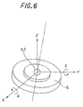
- ⁇ and ⁇ indicate a tilt with respect to an X-axis and a tilt with respect to a Y-axis, respectively.
- the X-axis and the Y-axis lie along a horizontal plane.
- the carrier 6 performs a combined motion consisting of tilting with respect to the X-axis and tilting with respect to the Y-axis about the bearing ball 42 acting as the center of rotation.
- the error signals e ⁇ and e ⁇ . are subjected to a tilt control and attenuation processing in a PID + local phase-lead processing section 31-1 and are further passed through a notch filter 31-2 to remove vibrational components, and converted into voltage command signals V ⁇ and V ⁇ . Then, in a coordinate converter 31-3, the voltage command signals V ⁇ and V ⁇ . are converted into control signals V xu and V yu output by the attitude controller for supply to a driver section 32.
- the driver section 32 includes the electromagnetic coils 13a, 13b, 13c and 13d and drive circuits 24 for exciting these coils.
- the control signals V xu and V yu are supplied to the respective drive circuits 24, in which they are converted into excitation currents I xu +, I xu -, I yu + and I yu - for displacing the armature 14 in any of the positive and negative directions of the X- and Y-axes shown in Fig. 3.
- the excitation currents I xu +, I xu -, I yu +, and I yu - are supplied to the electromagnetic coils 13a, 13b, 13c and 13d to control the attitude of the controlled system (carrier 6).
- the center of rotation (bearing ball 42) of the carrier 6 and the X- and Y-axes of the armature 14 shown in Fig. 3 are apart from each other by a predetermined height (L). Therefore, when the armature 14 is displaced in the positive or negative direction of the X- or Y-axis shown in Fig. 3, the carrier body 9, that is, the carrier 6, can be tilted in the desired direction with respect to the horizontal plane about the bearing ball 42 as the center of rotation.
- the semiconductor wafer 3 carried by the wafer carrier 6 is pressed by the air cylinder 22 against the polishing cloth 2 which is being rotated by the motor, while an abrasive liquid Q is supplied onto the polishing cloth 2.
- the force for pressing the wafer 3 is transferred through the drive shaft 7 and the universal coupling 8 to the wafer carrier body 9 holding the wafer 3.
- the abrasive liquid Q supplied from the nozzle 60 flows between the wafer 3 and the polishing cloth 2 to facilitate polishing of the wafer.
- the attitude of the carrier body 9 is controlled by the attitude controller 11.
- the tilt of the carrier body 9 is detected by processing the outputs of the displacement sensors 15 (15a 1 , 15a 2 ; 15b 1 , 15b 2 ; 15c 1 , 15c 2 ; and 15d 1 , 15d 2 ) so that the carrier body 9 is controllably oriented relative to a horizontal plane in accordance with any inclination in the polishing surface of the polishing cloth 2 which is in contact with the wafer, in order to maintain the surface of the wafer to be polished strictly parallel with the polishing surface, with the pressure applied to the surface of the wafer to be polished is being controlled to be kept uniform across the entire area thereof.
- a force for pressing the carrier body 9 against the polishing surface of the turntable 1 is obtained by transmitting the pressing force of the air cylinder 22 directly to the carrier 6.
- the attitude controller 11 is used only to the control the tilt of the carrier. Consequently, the attitude controller 11 is able to be compact in size and simple in structure.
- the state of the polishing surface on the upper side of the turntable 1, including undulations or the like are previously measured and input to the controller so that an optimum attitude or orientation of the carrier 6 is obtained on the basis of the data input in advance.
- optimum attitude of the carrier 6 is effected by the attitude controller 11 on the basis of the detection of the attitude by means of the displacement sensors 15.
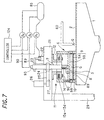
- FIGs. 7 and 8 there is shown a second embodiment of a polishing apparatus with the attitude controller 11 as described above for controlling the attitude of the wafer carrier 6.
- the holding plate 9A of the carrier body 9 is made of a flexible member and the gap G between the holding plate 9A and the mounting plate 9B is adapted to be supplied with a fluid pressure.
- the retainer ring 10 is movable in a vertical direction relative to the wafer carrier 6.
- the retainer ring 10 is provided on its upper portion with a fluid bag 88 so that the retainer ring 10 is pressed against the polishing cloth 2 independently of the wafer carrier by introducing a fluid pressure into the bag 88.
- the gap G is fluidly communicated with a fluid pressure source 85 through a tube 89 having a regulator R 1 .
- the holding plate 9A is made thin as a whole so that, when the gap G is pressurized or depressurized by the fluid pressure introduced therein, the lower surface of the holding plate 9A is uniformly deformed as a whole.
- the retainer ring 10 includes a first retainer ring element 10a and a second retainer ring element 10b having a cross-section in the form of a reversed "L" and fixed on the first retainer element 10a.
- the second retainer ring element 10b is fixedly connected by a plurality of pins 99 to the mounting plate 9B of the wafer carrier body 9 at its upper end to enable the retainer ring 10 to rotate together with the wafer carrier 6.
- the fluid bag 88 is annular and located between the retainer ring 10 and the wafer carrier 6 and fixed to the holding plate 9A.
- the bag 88 is fluidly connected to the fluid pressure source 85 through a tube 90 having a regulator R 2 . As shown in Fig.
- the wafer carrier actuating cylinder 22 is connected to the fluid pressure source 85 through a tube having a regulator R 3 .
- the lower surface (wafer holding surface) of the holding plate 9A is controllably deformed in both a concave and convex manner in a vertical direction by controlling a pressure in the gap G.
- the regulators R 1 , R 2 , R 3 are connected to a controller 124 to effect control thereof, whereby the pressures applied to the wafer 3 and the retainer ring 10 can be appropriately controlled. It is possible for the pressures under which the retainer ring 10 and the wafer 3 are pressed against the polishing cloth to be controlled independently from each other.
- the wafer carrier 6 is provided with an additional fluid line system including a through hole 2h formed in the mounting plate 9B, a through hole 3h formed in the holding plate 9A, a connecting tube 126 connecting the through holes 2h and 3h, and a fitting 127 which is fluidly connected to a pressure source (not shown).
- the fluid line system enables the lower surface of the holding plate 9A to securely hold the wafer 3 under the influence of a vacuum applied to the upper surface of the wafer 3 through the fluid line system; for example, when the wafer is brought into contact with the polishing cloth 2 from the outside of the turntable. In a condition that the wafer held on the lower surface of the holding plate 9A is engaged with the polishing cloth 2 as shown in Fig.
- the attitude controller 11 is substantially the same as that employed in the afore-mentioned embodiments in that the attitude controller 11 includes the annular armature 14 fixed to the mounting plate 9B and the electromagnetic core 12 fixed to the carrier head 21 and provided with the electromagnetic coils 13a-13d.
- the controller 11 controls the attitude of the wafer carrier 6 in the same manner as that described in connection with the first embodiment.
- Figs. 9, 10 and 11 show a third embodiment of a polishing apparatus of the present invention with the wafer carrier attitude controller 11 as described above.
- the polishing apparatus of this embodiment additionally includes a pressing ring 133 provided radially outside the retainer ring 10.
- the pressing ring 133 includes a first ring element 133a made from alumina-ceramic and second and third ring elements 133b and 133c made from stainless steel.
- the first and second ring elements 133a and 133b are bonded to each other with an adhesive and the second and third ring elements 133b and 133c are connected by bolts (not shown).
- the lower surface of the first ring element 133a constitutes a pressing surface 133f for pressing the polishing cloth 2.
- the pressing element 133 is supported by an annular bearing 137 provided between the third ring element 133c and a cylindrical bearing raceway member 136 fixedly connected to the mounting plate 9B of the wafer carrier 6.
- the annular bearing 137 includes an annular bearing case 137a and a number of ball bearings 137b which are supported by ball bearing retainer means (not shown) in such a manner that they are, as shown in Figs. 10 and 11, arranged along horizontal upper and lower circles in the bearing case 137a.
- the bearing case 137a is fastened to the third ring element 133c by a fastener 150 provided on the top end of the third ring element 133c.
- the bearing 137 makes it possible for the pressing ring 133 to be stationary while the wafer carrier 6 rotates inside the pressing ring 133. Accordingly, the pressing ring 133 is pressed by the air cylinder devices 122 against the polishing cloth 2 around the retainer ring 10 during polishing of the wafer 3 to optimize the polishing surface condition radially outside and adjacent to the periphery of the wafer 3.
- the wafer carrier attitude controller 11 is substantially the same as that employed in the aforementioned embodiments.
- the annular armature 14 is fixed to the pressing ring 133 and the electromagnetic core 12 is fixed to the carrier head 21 and provided with the electromagnetic coils 13a-13d.
- the controller 11 controls the attitude of the pressing ring 133 (and thus the wafer carrier 6) in the same manner as that described in connection with the other embodiments.
- the holding plate 9A of the wafer carrier 6 is formed with a plurality of through holes 135 connecting the gap G to the lower surface of the holding plate 9A.
- a resilient pad 132 which includes a plurality of through holes corresponding to the through holes 135 formed in the holding plate 9A.
- the lower end portion of the retainer ring 10 is made thin in its radial direction so as to make it possible for the pressing ring 133 or the first ring element 133a thereof to be placed closer to the periphery of the wafer 3 held by the wafer carrier.
- FIGs. 12 and 13 there is shown a fourth embodiment of a polishing apparatus with the attitude controller 11 as described above in connection with the other embodiments.
- This polishing apparatus is substantially the same as that shown in Figs. 9, 10 and 11 except for the bearing supporting the pressing ring 133 on the wafer carrier 6.
- the bearing consists of two kinds of bearings 138 and 139.
- the bearing 138 is a conventional radial bearing for allowing the wafer carrier to rotate relative to the pressing ring 133 which is kept stationary, while maintaining the positional relationship in the vertical direction between the wafer carrier 6 and the pressing ring 133.
- the bearings 139 are, as shown in Fig. 13, provided around the wafer carrier 6 at an angular interval of 120° and allow relative movement between the pressing ring 133 and the wafer carrier 6 in a vertical direction.
- the bearing 139 includes an outside raceway member 139a, cylindrical bearings 139b which are arranged in two rows and two columns and an inside raceway member 139c.
- the bearing 138 is provided between the inside raceway member 139c and the mounting plate 9B of the wafer carrier 6.
- the above-described bearing construction enables the bearings to be used for a longer period than that employed in the embodiment shown in Figs. 9 - 11. It should be noted that in this embodiment, labyrinth seals 175, 176, 177 are employed for the bearings 138 and 139 to prevent foreign particles from entering into the bearings.
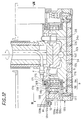
- FIGs. 14 - 18 there is shown a polishing apparatus in accordance with a fifth embodiment of the present invention.
- This embodiment differs from the other embodiments in that the wafer carrier 6 is not provided with an attitude controller as explained above in connection with the other embodiments and, instead, a similar attitude controller 111 is provided for the turntable 1.
- the turntable 1 is connected to a rotating shaft 102 of a motor (not shown) through a universal joint including upper and lower coupling members 103 and 104.
- the lower coupling member 104 is secured to the upper end of the rotating shaft 102 of the motor.
- the upper coupling member 103 is secured to the lower surface of the turntable 1.
- a self-aligning roller bearing 105 is disposed between the lower coupling member 104 and the upper coupling member 103 to allow the turntable 1 and the upper coupling member 103 to tilt in any direction desired with respect to the lower coupling member 104 about the self-aligning roller bearing 105 as the center of rotation.
- the universal joint further includes a short column-shaped pin 106 which is fixed to the coupling member 104 and is engaged with an engagement hole 103a formed in the upper coupling member 103 to transmit rotation from the shaft 102 to the turntable 1. It should be noted that a predetermined clearance is formed between the engagement hole 103a and the pin 106 so that tilting of the turntable 1 is allowed.
- the turntable attitude controller 111 for controlling the attitude of the turntable 1 includes an electromagnetic core 112 secured to a frame 128.
- the electromagnetic core 112 is provided with four magnetic poles 112a, 112b, 112c and 112d.
- Four electromagnetic coils 113a, 113b, 113c and 113d are wound on the magnetic poles 112a to 112d, respectively.
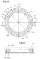
- the attitude controller 111 further includes an annular disk-shaped armature 114 facing the magnetic poles 112a to 112d across a gap. The armature 114 is secured to the turntable 1.
- the magnetic poles 112a to 112d each have an inverted U-shaped sectional configuration.
- the inner portions of the inverted U-shaped magnetic poles 112a to 112d are wound with the electromagnetic coils 113a to 113d, respectively.
- the magnetic poles 112a to 112d and the armature 114 are formed from a magnetic material, e.g. a permalloy.
- the electromagnetic coil 113a is placed at a position in positive alignment with the X-axis.
- the electromagnetic coil 113b is placed at a position in negative alignment with the X-axis.
- the electromagnetic coil 113c is placed at a position in positive alignment with the Y-axis.
- the electromagnetic coil 113d is placed at a position in negative alignment with the Y-axis.
- Four displacement sensors 115a, 115b, 115c and 115d are placed on two axes R and S tilted at 45 degrees with respect to the X- and Y-axes.
- Fig. 18 is a block diagram showing the functional arrangement of a control part for controlling the attitude controller 111. As shown in the figure, the control part is substantially the same as that of the control part shown in Fig. 5 in both arrangement and function.
- Figs. 19 and 20 show another embodiment of the electromagnetic core 112 which is provided with eight electromagnetic coils 112a - 112h arranged at an equal angular interval of 45° and gap sensors 115a - 115d at an equal angular interval of 90°.
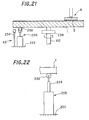
- Figs. 21 and 22 shows a sixth embodiment or a variation of the fifth embodiment shown in Figs. 14 and 15.
- the controller includes a plurality of air cylinder devices 220 (only one is shown) arranged around the turntable drive shaft 221 at an equal angular interval under the periphery of the turntable 1.
- the cylinder device 220 includes a cylinder body fixed to the stationary frame 222 and a rod extending from the cylinder body upward. The rod is provided on its upper end with a roller 230 which rotatably engages with the lower surface of the turntable 1.
- the controller further includes a gap sensor 234 adapted to sense a gap between the sensor 234 and the lower surface of the turntable 1.
- a gap sensor 234 adapted to sense a gap between the sensor 234 and the lower surface of the turntable 1.
- the rods of the cylinder devices are extended or retracted so as to control the attitude of the turntable.
- control part of the controller is omitted, as it is substantially the same as that of the controllers for the wafer carrier and turntable explained in connection with the other embodiments.
- reference numeral 238 designates a universal joint for connecting the drive shaft 221 and the turntable 1.
- Fig. 23 shows a seventh embodiment or a variation of the fifth embodiment.
- the turntable drive shaft 221 has a disc 250 fixed thereto and a plurality of cylinder devices 252 are fixedly provided between the disc 250 and the turntable 1.
- Gap sensors (not shown) similar to those 234 employed in the sixth embodiment are mounted on the disc 250. The attitude of the turntable 1 is effected in the same manner that in the sixth embodiment.
- Figs. 24 and 25 show a eighth embodiment of the present invention or a combination of the embodiment shown in Figs. 1 - 6 and the embodiment shown in Figs. 14 - 18. For the purpose of simplicity, detailed explanation thereabout is omitted.
- Fig. 25 is a block diagram showing the functional arrangement of a combination of a control part for controlling the turntable attitude controller 111 and a control part for controlling the wafer carrier attitude controller 11. As shown in the figure, the turntable control part and the wafer carrier control part each have an arrangement similar to that of the control part shown in Figs. 5 and 18. Elements of the wafer carrier control part which are the same as those in Fig.
- the arrangement shown in Fig. 25 is additionally provided with a computing device 36 for precisely detecting relative positions of the carrier and the turntable on the basis of signals input thereto from the carrier control part and the turntable control part.
- the computing device 36 computes relative errors from information concerning the tilt of the carrier and information concerning the tilt of the turntable to generate rectified displacement values ⁇ , ⁇ , ⁇ ' and ⁇ ' , thereby allowing control to be effected with a high degree of accuracy.
- the degree of accuracy can be increased by correcting the desired position of the carrier with reference to the tilt of the turntable.
- the feedback R2 to the turntable may be omitted.
- the computing device may be omitted.
- the attitude of the wafer carrier and/or the turntable is controlled so that a polishing operation can be carried out while maintaining a distribution of pressure under which a wafer is pressed against the polishing cloth uniform across the entire wafer surface engaged with the polishing cloth. Accordingly, it is possible to obtain a polished surface having a high degree of flatness.
Landscapes
- Engineering & Computer Science (AREA)
- Mechanical Engineering (AREA)
- Finish Polishing, Edge Sharpening, And Grinding By Specific Grinding Devices (AREA)
- Mechanical Treatment Of Semiconductor (AREA)
Abstract
Description
Claims (21)
- A polishing apparatus comprising:a turntable having a polishing surface that comes into sliding contact with an object to be polished,a support for tiltably supporting said turntable, and,an attitude controller for controlling an attitude or orientation of said turntable.
- A polishing apparatus according to Claim 1, wherein said attitude controller controls the attitude of said turntable by controlling an angle of tilting of said turntable relative to said support by means of an electromagnetic force.
- A polishing apparatus according to Claim 2, wherein said polishing apparatus includes a stationary frame, and said attitude controller comprises:an electromagnetic device fixedly provided on said stationary frame of said polishing apparatus, andarmature means fixedly provided on said turntable and adapted to be moved by means of an electromagnetic force generated by said electromagnetic device.
- A polishing apparatus according to Claim 2, wherein said polishing apparatus includes a stationary frame, andsaid attitude controller comprises cylinder device means provided under said turntable and fixed to said stationary frame of said polishing apparatus and engaged with a lower surface of said turntable so that said cylinder device means controls the attitude of said turntable by extension and contraction thereof.
- A polishing apparatus comprising:a turntable having a polishing surface,a carrier for holding an article to be polished in a sliding contact relation with said polishing surface,a pressing means connected to said carrier and adapted to press said carrier towards said turntable with said article engaged with said polishing surface, andan attitude controller for controlling an attitude or orientation of said carrier.
- A polishing apparatus according to Claim 5, wherein said pressing means is a drive shaft for drivingly rotating said carrier and said polishing apparatus includes a universal joint connecting said drive shaft and said carrier in such a manner that the carrier can tilt relative to said drive shaft.
- A polishing apparatus according to Claim 6, wherein said polishing apparatus includes a frame for supporting said drive shaft in such a manner that the drive shaft rotates about its axis, and said attitude controller comprises:an electromagnetic device fixedly provided on said frame, andarmature means fixedly provided on said carrier and adapted to be moved by means of an electromagnetic force generated by said electromagnetic device.
- A polishing apparatus according to Claim 7, wherein said attitude controller includes sensor means for sensing the attitude or orientation of said carrier so that said attitude controller controls the attitude of said wafer in response to the sensed attitude or orientation.
- A polishing apparatus in accordance with Claim 5 or 6, wherein said polishing apparatus further includes:a pressing member provided radially outside said carrier and movable up and down independently of said carrier,an urging device for urging said pressing member, anda bearing for supporting said pressing member on said carrier in such a manner that the pressing member is kept stationary while allowing said carrier to rotate.
- A polishing apparatus in accordance with Claim 5 or 6, wherein said carrier includes a mounting member connected to said pressing means and an article holding member with a gap interposed therebetween, and said article holding member has a lower surface for holding an article to be polished and is flexible so that it can be deformed in both a concave and convex manner in a vertical direction by controlling a pressure in said gap G.
- A polishing apparatus in accordance with Claim 10, wherein said carrier includes a retainer ring provided on the outer periphery of said carrier to confine the article held on said lower surface of said holding member, said retainer ring is movable vertically relative to said holding member, and said carrier further includes a pressing means for pressing said retainer ring vertically against said polishing surface of said turntable.
- A polishing apparatus comprising:a turntable having a polishing,a support for tiltably supporting said turntable,a turntable attitude controller for controlling an attitude or orientation of said turntable,a carrier for holding an article to be polished in a sliding contact relation with said polishing surface,a pressing means connected to said carrier and adapted to press said carrier towards said turntable with said article engaged with said polishing surface, anda carrier attitude controller for controlling an attitude or orientation of said carrier.
- A polishing apparatus according to Claim 12, wherein said turntable attitude controller controls the attitude of said turntable by controlling an angle of tilting of said turntable relative to said support means by means of an electromagnetic force.
- A polishing apparatus according to Claim 13, wherein said polishing apparatus includes a stationary frame, and said turntable attitude controller comprises:an electromagnetic device fixedly provided on said stationary frame of said polishing apparatus, andarmature means fixedly provided on said turntable and adapted to be moved by means of an electromagnetic force generated by said electromagnetic device.
- A polishing apparatus according to Claim 13, wherein said polishing apparatus includes a stationary frame, and said turntable attitude controller comprises cylinder device means provided under said turntable and fixed to said stationary frame of said polishing apparatus and engaged with a lower surface of said turntable so that said cylinder device means controls the attitude of said turntable by extension and contraction thereof.
- A polishing apparatus according to Claim 15, wherein said pressing means is a drive shaft for drivingly rotating said carrier and said polishing apparatus includes a universal joint connecting said drive shaft and said carrier in such a manner that the carrier can tilt relative to said drive shaft.
- A polishing apparatus according to Claim 16, wherein said polishing apparatus includes a frame for supporting said drive shaft in such a manner that the drive shaft rotates about its axis, and said carrier attitude controller comprises:an electromagnetic device fixedly provided on said frame, andarmature means fixedly provided on said carrier and adapted to be moved by means of an electromagnetic force generated by said electromagnetic device.
- A polishing apparatus according to Claim 17, wherein said carrier attitude controller includes sensor means for sensing the attitude or orientation of said carrier so that said carrier attitude controller controls the attitude of said wafer in response to the sensed attitude or orientation.
- A polishing apparatus in accordance with Claim 15 or 16, wherein said polishing apparatus further includes:a pressing member provided radially outside said carrier and movable up and down independently of said carrier,an urging device for urging said pressing member, anda bearing for supporting said pressing member on said carrier in such a manner that the pressing member is kept stationary while allowing said carrier to rotate.
- A polishing apparatus in accordance with Claim 15 or 16, wherein said carrier includes a mounting member connected to said pressing means and an article holding member with a gap interposed therebetween, and said article holding member has a lower surface for holding an article to be polished and is flexible so that it can be deformed in both a concave and convex manner in a vertical direction by controlling a pressure in said gap G.
- A polishing apparatus in accordance with Claim 20, wherein said carrier includes a retainer ring provided on the outer periphery of said carrier to confine the article held on said lower surface of said holding member, said retainer ring is movable vertically relative to said holding member, and said carrier further includes a pressing means for pressing said retainer ring vertically against said turntable.
Priority Applications (1)
| Application Number | Priority Date | Filing Date | Title |
|---|---|---|---|
| EP05005450A EP1537949A3 (en) | 1999-03-11 | 2000-03-13 | Polishing apparatus including attitude controller for wafer carrier and turntable |
Applications Claiming Priority (4)
| Application Number | Priority Date | Filing Date | Title |
|---|---|---|---|
| JP6570899 | 1999-03-11 | ||
| JP6570999 | 1999-03-11 | ||
| JP6570899 | 1999-03-11 | ||
| JP6570999 | 1999-03-11 |
Related Child Applications (1)
| Application Number | Title | Priority Date | Filing Date |
|---|---|---|---|
| EP05005450A Division EP1537949A3 (en) | 1999-03-11 | 2000-03-13 | Polishing apparatus including attitude controller for wafer carrier and turntable |
Publications (3)
| Publication Number | Publication Date |
|---|---|
| EP1034885A2 true EP1034885A2 (en) | 2000-09-13 |
| EP1034885A3 EP1034885A3 (en) | 2001-03-21 |
| EP1034885B1 EP1034885B1 (en) | 2005-06-15 |
Family
ID=26406850
Family Applications (2)
| Application Number | Title | Priority Date | Filing Date |
|---|---|---|---|
| EP00104555A Expired - Lifetime EP1034885B1 (en) | 1999-03-11 | 2000-03-13 | Polishing apparatus including attitude controller for turntable and/or wafer carrier |
| EP05005450A Withdrawn EP1537949A3 (en) | 1999-03-11 | 2000-03-13 | Polishing apparatus including attitude controller for wafer carrier and turntable |
Family Applications After (1)
| Application Number | Title | Priority Date | Filing Date |
|---|---|---|---|
| EP05005450A Withdrawn EP1537949A3 (en) | 1999-03-11 | 2000-03-13 | Polishing apparatus including attitude controller for wafer carrier and turntable |
Country Status (5)
| Country | Link |
|---|---|
| US (1) | US6354907B1 (en) |
| EP (2) | EP1034885B1 (en) |
| KR (1) | KR100695981B1 (en) |
| DE (1) | DE60020759T2 (en) |
| TW (1) | TW467792B (en) |
Cited By (4)
| Publication number | Priority date | Publication date | Assignee | Title |
|---|---|---|---|---|
| WO2002024409A1 (en) * | 2000-09-21 | 2002-03-28 | Nikon Corporation | Polishing apparatus with electromagnetical attitude controller for the polishing pad carrier |
| EP1676673A1 (en) * | 2004-12-28 | 2006-07-05 | Toyota Jidosha Kabushiki Kaisha | Attitude control device and precision machining apparatus comprising same |
| CN114683128A (en) * | 2022-06-02 | 2022-07-01 | 成都泰美克晶体技术有限公司 | Thin wafer edge polishing equipment |
| CN120395664A (en) * | 2025-07-01 | 2025-08-01 | 江苏圣欣不锈钢制品有限公司 | A stainless steel product inner circle polishing device |
Families Citing this family (34)
| Publication number | Priority date | Publication date | Assignee | Title |
|---|---|---|---|---|
| JP4487353B2 (en) * | 1999-11-26 | 2010-06-23 | ソニー株式会社 | Polishing apparatus and polishing method |
| US6609950B2 (en) * | 2000-07-05 | 2003-08-26 | Ebara Corporation | Method for polishing a substrate |
| US6652357B1 (en) * | 2000-09-22 | 2003-11-25 | Lam Research Corporation | Methods for controlling retaining ring and wafer head tilt for chemical mechanical polishing |
| US6709322B2 (en) * | 2001-03-29 | 2004-03-23 | Lam Research Corporation | Apparatus for aligning a surface of an active retainer ring with a wafer surface for chemical mechanical polishing |
| US20040011149A1 (en) * | 2002-04-03 | 2004-01-22 | David Carroll | Integrated angular and radial position sensor |
| JP4269259B2 (en) * | 2003-05-30 | 2009-05-27 | 株式会社ニコン | Processing apparatus and semiconductor device manufacturing method using the processing apparatus |
| JP2005034959A (en) * | 2003-07-16 | 2005-02-10 | Ebara Corp | Polishing device and retainer ring |
| US8083571B2 (en) | 2004-11-01 | 2011-12-27 | Ebara Corporation | Polishing apparatus |
| US7494404B2 (en) * | 2006-02-17 | 2009-02-24 | Chien-Min Sung | Tools for polishing and associated methods |
| US7241206B1 (en) * | 2006-02-17 | 2007-07-10 | Chien-Min Sung | Tools for polishing and associated methods |
| KR101022277B1 (en) * | 2009-02-25 | 2011-03-21 | 그린스펙(주) | Carrier Head for Silicon Bare Wafer Polishing Machine |
| CN102152256B (en) * | 2010-02-11 | 2013-09-04 | 创研精密股份有限公司 | Rod positioning device |
| DE102012010004A1 (en) | 2012-05-22 | 2013-11-28 | Satisloh Ag | Method for grinding workpieces, in particular for centering grinding of workpieces such as optical lenses |
| US10702972B2 (en) | 2012-05-31 | 2020-07-07 | Ebara Corporation | Polishing apparatus |
| JP5976522B2 (en) * | 2012-05-31 | 2016-08-23 | 株式会社荏原製作所 | Polishing apparatus and polishing method |
| CN102729134A (en) * | 2012-07-21 | 2012-10-17 | 深圳市华测检测技术股份有限公司 | Portable automatic grinding and polishing equipment |
| US9011207B2 (en) * | 2012-10-29 | 2015-04-21 | Wayne O. Duescher | Flexible diaphragm combination floating and rigid abrading workholder |
| US8998678B2 (en) * | 2012-10-29 | 2015-04-07 | Wayne O. Duescher | Spider arm driven flexible chamber abrading workholder |
| US9039488B2 (en) * | 2012-10-29 | 2015-05-26 | Wayne O. Duescher | Pin driven flexible chamber abrading workholder |
| US8998677B2 (en) * | 2012-10-29 | 2015-04-07 | Wayne O. Duescher | Bellows driven floatation-type abrading workholder |
| CN103753378A (en) * | 2014-01-16 | 2014-04-30 | 深圳市华测检测技术股份有限公司 | Hydraulic semi-automatic constant-pressure grinding and polishing equipment |
| TWI656944B (en) * | 2014-05-14 | 2019-04-21 | 日商荏原製作所股份有限公司 | Polishing apparatus |
| JP6216686B2 (en) | 2014-05-30 | 2017-10-18 | 株式会社荏原製作所 | Polishing equipment |
| JP6269450B2 (en) * | 2014-11-18 | 2018-01-31 | 信越半導体株式会社 | Workpiece processing equipment |
| KR101679131B1 (en) * | 2014-12-29 | 2016-11-23 | 주식회사 엘지실트론 | Wafer's final polishing apparatus and final polishing method by it |
| JP6592355B2 (en) | 2015-01-30 | 2019-10-16 | 株式会社荏原製作所 | Connecting mechanism and substrate polishing apparatus |
| JP6815799B2 (en) | 2016-09-13 | 2021-01-20 | 東京エレクトロン株式会社 | Substrate processing equipment and substrate processing method |
| USD827689S1 (en) * | 2017-05-22 | 2018-09-04 | Daniel Turner | Orbital gear replacement insert |
| JP7049984B2 (en) * | 2018-12-27 | 2022-04-07 | 株式会社荏原製作所 | How to control the tilt of the grinder and the stationary ring |
| KR102721972B1 (en) | 2019-07-08 | 2024-10-29 | 삼성전자주식회사 | rotation body module and chemical mechanical polishing apparatus having the same |
| CN110861001B (en) * | 2019-12-04 | 2020-09-22 | 东阳东磁自动化科技有限公司 | Pulley lifting type magnetic suction feeding mechanism and implementation method thereof |
| CN112872960B (en) * | 2021-02-03 | 2025-02-18 | 浙江晶盛机电股份有限公司 | Wafer edge polishing device and polishing method |
| CN114603403B (en) * | 2022-03-15 | 2023-05-26 | 先导薄膜材料(广东)有限公司 | Processing method of diamond angle sputtering target material |
| US20250041985A1 (en) * | 2023-08-04 | 2025-02-06 | Applied Materials, Inc. | Pad conditioning disk gimbaling control |
Family Cites Families (8)
| Publication number | Priority date | Publication date | Assignee | Title |
|---|---|---|---|---|
| US5476414A (en) * | 1992-09-24 | 1995-12-19 | Ebara Corporation | Polishing apparatus |
| US5908530A (en) * | 1995-05-18 | 1999-06-01 | Obsidian, Inc. | Apparatus for chemical mechanical polishing |
| JPH1058308A (en) * | 1996-05-29 | 1998-03-03 | Ebara Corp | Polishing device |
| US5951368A (en) * | 1996-05-29 | 1999-09-14 | Ebara Corporation | Polishing apparatus |
| JP3807807B2 (en) * | 1997-02-27 | 2006-08-09 | 株式会社荏原製作所 | Polishing device |
| EP1327498B1 (en) * | 1997-04-08 | 2013-06-12 | Ebara Corporation | Polishing apparatus |
| US6080040A (en) * | 1997-11-05 | 2000-06-27 | Aplex Group | Wafer carrier head with inflatable bladder and attack angle control for polishing |
| JP2000005988A (en) * | 1998-04-24 | 2000-01-11 | Ebara Corp | Polishing device |
-
2000
- 2000-03-10 TW TW089104396A patent/TW467792B/en not_active IP Right Cessation
- 2000-03-10 US US09/522,705 patent/US6354907B1/en not_active Expired - Fee Related
- 2000-03-11 KR KR1020000012245A patent/KR100695981B1/en not_active Expired - Fee Related
- 2000-03-13 EP EP00104555A patent/EP1034885B1/en not_active Expired - Lifetime
- 2000-03-13 EP EP05005450A patent/EP1537949A3/en not_active Withdrawn
- 2000-03-13 DE DE60020759T patent/DE60020759T2/en not_active Expired - Fee Related
Cited By (7)
| Publication number | Priority date | Publication date | Assignee | Title |
|---|---|---|---|---|
| WO2002024409A1 (en) * | 2000-09-21 | 2002-03-28 | Nikon Corporation | Polishing apparatus with electromagnetical attitude controller for the polishing pad carrier |
| US6857950B2 (en) | 2000-09-21 | 2005-02-22 | Nikon Corporation | Polishing apparatus, semiconductor device manufacturing method using the polishing apparatus, and semiconductor device manufactured by the manufacturing method |
| EP1676673A1 (en) * | 2004-12-28 | 2006-07-05 | Toyota Jidosha Kabushiki Kaisha | Attitude control device and precision machining apparatus comprising same |
| US7160175B2 (en) | 2004-12-28 | 2007-01-09 | Toyota Jidosha Kabushiki Kaisha | Attitude control device and precision machining apparatus |
| CN114683128A (en) * | 2022-06-02 | 2022-07-01 | 成都泰美克晶体技术有限公司 | Thin wafer edge polishing equipment |
| CN120395664A (en) * | 2025-07-01 | 2025-08-01 | 江苏圣欣不锈钢制品有限公司 | A stainless steel product inner circle polishing device |
| CN120395664B (en) * | 2025-07-01 | 2025-09-12 | 江苏圣欣不锈钢制品有限公司 | Stainless steel product inner circle polishing device |
Also Published As
| Publication number | Publication date |
|---|---|
| KR20000062839A (en) | 2000-10-25 |
| EP1537949A3 (en) | 2005-06-15 |
| EP1034885A3 (en) | 2001-03-21 |
| KR100695981B1 (en) | 2007-03-15 |
| US6354907B1 (en) | 2002-03-12 |
| DE60020759T2 (en) | 2006-05-11 |
| EP1034885B1 (en) | 2005-06-15 |
| TW467792B (en) | 2001-12-11 |
| EP1537949A2 (en) | 2005-06-08 |
| DE60020759D1 (en) | 2005-07-21 |
Similar Documents
| Publication | Publication Date | Title |
|---|---|---|
| EP1034885B1 (en) | Polishing apparatus including attitude controller for turntable and/or wafer carrier | |
| US6520845B2 (en) | Polishing apparatus | |
| US6168684B1 (en) | Wafer polishing apparatus and polishing method | |
| EP2000259B1 (en) | Substrate holding apparatus, polishing apparatus, and polishing method | |
| US5908530A (en) | Apparatus for chemical mechanical polishing | |
| US5816895A (en) | Surface grinding method and apparatus | |
| US5899798A (en) | Low profile, low hysteresis force feedback gimbal system for chemical mechanical polishing | |
| KR100478989B1 (en) | Polishing device | |
| KR100939096B1 (en) | Polishing apparatus, polishing method and substrate carrier system | |
| US20100190417A1 (en) | Apparatus for dressing a polishing pad, chemical mechanical polishing apparatus and method | |
| EP1034886B1 (en) | Polishing apparatus including attitude controller for dressing apparatus | |
| JPH05131359A (en) | Device for polishing both surfaces at equal speed and method for its use | |
| US6196904B1 (en) | Polishing apparatus | |
| US6196903B1 (en) | Workpiece carrier and polishing apparatus having workpiece carrier | |
| US6315641B1 (en) | Method and apparatus for chemical mechanical polishing | |
| JPH0317622B2 (en) | ||
| JP3862920B2 (en) | Polishing apparatus provided with attitude control device for substrate holding device | |
| US8251775B2 (en) | Mechanism and method for detecting the motion of a shaft | |
| JPH07290356A (en) | Polishing equipment | |
| JP3872629B2 (en) | Polishing device provided with attitude control device for turntable device | |
| JP2019171492A (en) | Substrate holding device and manufacturing method of drive ring | |
| JP2000263401A (en) | Wafer polishing apparatus and wafer manufacturing method | |
| JP2000326218A (en) | Wafer polishing apparatus and wafer manufacturing method | |
| JP3152763B2 (en) | Polishing equipment | |
| JPH10296622A (en) | Polishing device |
Legal Events
| Date | Code | Title | Description |
|---|---|---|---|
| PUAI | Public reference made under article 153(3) epc to a published international application that has entered the european phase |
Free format text: ORIGINAL CODE: 0009012 |
|
| AK | Designated contracting states |
Kind code of ref document: A2 Designated state(s): DE FR |
|
| AX | Request for extension of the european patent |
Free format text: AL;LT;LV;MK;RO;SI |
|
| RIC1 | Information provided on ipc code assigned before grant |
Free format text: 7B 24B 37/04 A, 7B 24B 31/00 B |
|
| PUAL | Search report despatched |
Free format text: ORIGINAL CODE: 0009013 |
|
| AK | Designated contracting states |
Kind code of ref document: A3 Designated state(s): AT BE CH CY DE DK ES FI FR GB GR IE IT LI LU MC NL PT SE |
|
| AX | Request for extension of the european patent |
Free format text: AL;LT;LV;MK;RO;SI |
|
| 17P | Request for examination filed |
Effective date: 20010920 |
|
| AKX | Designation fees paid |
Free format text: DE FR |
|
| 17Q | First examination report despatched |
Effective date: 20030704 |
|
| GRAP | Despatch of communication of intention to grant a patent |
Free format text: ORIGINAL CODE: EPIDOSNIGR1 |
|
| GRAS | Grant fee paid |
Free format text: ORIGINAL CODE: EPIDOSNIGR3 |
|
| GRAA | (expected) grant |
Free format text: ORIGINAL CODE: 0009210 |
|
| AK | Designated contracting states |
Kind code of ref document: B1 Designated state(s): DE FR |
|
| REF | Corresponds to: |
Ref document number: 60020759 Country of ref document: DE Date of ref document: 20050721 Kind code of ref document: P |
|
| ET | Fr: translation filed | ||
| PLBE | No opposition filed within time limit |
Free format text: ORIGINAL CODE: 0009261 |
|
| STAA | Information on the status of an ep patent application or granted ep patent |
Free format text: STATUS: NO OPPOSITION FILED WITHIN TIME LIMIT |
|
| 26N | No opposition filed |
Effective date: 20060316 |
|
| PGFP | Annual fee paid to national office [announced via postgrant information from national office to epo] |
Ref country code: DE Payment date: 20090330 Year of fee payment: 10 |
|
| PGFP | Annual fee paid to national office [announced via postgrant information from national office to epo] |
Ref country code: FR Payment date: 20090312 Year of fee payment: 10 |
|
| REG | Reference to a national code |
Ref country code: FR Ref legal event code: ST Effective date: 20101130 |
|
| PG25 | Lapsed in a contracting state [announced via postgrant information from national office to epo] |
Ref country code: FR Free format text: LAPSE BECAUSE OF NON-PAYMENT OF DUE FEES Effective date: 20100331 |
|
| PG25 | Lapsed in a contracting state [announced via postgrant information from national office to epo] |
Ref country code: DE Free format text: LAPSE BECAUSE OF NON-PAYMENT OF DUE FEES Effective date: 20101001 |