EP1031996A2 - Adjustable assembly - Google Patents
Adjustable assembly Download PDFInfo
- Publication number
- EP1031996A2 EP1031996A2 EP00103667A EP00103667A EP1031996A2 EP 1031996 A2 EP1031996 A2 EP 1031996A2 EP 00103667 A EP00103667 A EP 00103667A EP 00103667 A EP00103667 A EP 00103667A EP 1031996 A2 EP1031996 A2 EP 1031996A2
- Authority
- EP
- European Patent Office
- Prior art keywords
- lever
- drive
- adjustable
- solid body
- rocker arm
- Prior art date
- Legal status (The legal status is an assumption and is not a legal conclusion. Google has not performed a legal analysis and makes no representation as to the accuracy of the status listed.)
- Withdrawn
Links
Images

Classifications
-
- G—PHYSICS
- G12—INSTRUMENT DETAILS
- G12B—CONSTRUCTIONAL DETAILS OF INSTRUMENTS, OR COMPARABLE DETAILS OF OTHER APPARATUS, NOT OTHERWISE PROVIDED FOR
- G12B5/00—Adjusting position or attitude, e.g. level, of instruments or other apparatus, or of parts thereof; Compensating for the effects of tilting or acceleration, e.g. for optical apparatus
-
- G—PHYSICS
- G02—OPTICS
- G02B—OPTICAL ELEMENTS, SYSTEMS OR APPARATUS
- G02B7/00—Mountings, adjusting means, or light-tight connections, for optical elements
- G02B7/02—Mountings, adjusting means, or light-tight connections, for optical elements for lenses
- G02B7/023—Mountings, adjusting means, or light-tight connections, for optical elements for lenses permitting adjustment
-
- G—PHYSICS
- G02—OPTICS
- G02B—OPTICAL ELEMENTS, SYSTEMS OR APPARATUS
- G02B7/00—Mountings, adjusting means, or light-tight connections, for optical elements
- G02B7/02—Mountings, adjusting means, or light-tight connections, for optical elements for lenses
- G02B7/026—Mountings, adjusting means, or light-tight connections, for optical elements for lenses using retaining rings or springs
Definitions
- the invention relates to an adjustable assembly according to the The preamble of claim 1 and an optical version as an embodiment the adjustable assembly.
- DD 278 207 A1 is an adjustment device for an optical Element known by the optical axes of individual optical elements opposite the mechanical axis of a lens can be aligned. Through the adjustment elements However, deviations of the optical axes from optical Elements from the axis of the lens not with one correct the high accuracy required today, e.g. for objects in semiconductor lithography is required.
- JP 10-54 932 shows a socket connection with a lever reduction in a multi-part design.
- the present invention has for its object a to create voltage decoupled assembly, especially for the mounting technique of an optical element, in which a adjustable tilted due to manufacturing and assembly tolerances Part, such as a lens as an optical element, through a Drive or manipulators tilted back to the target position can be.
- this task is characterized by Part of claim 1 mentioned features solved.
- the solution according to the invention allows a very high one Gear ratio in the fine through the drive on very small space for the adjustable part, e.g. an optical Element, achieve.
- This is done in that one of the two solid swivel joints divided into two swivel parts which is offset sideways along its axis of rotation on both sides of the second solid hinge are arranged.
- the distance between the solid-state swivel joints can be reducing the gear ratio significantly.
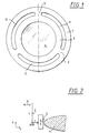
- the optics frame shown in principle in Figure 1 has a frame ring 1, which has three solid joints 2 is connected to an inner ring 3.
- the frame ring 1 and the inner ring 3 can be integrally formed his.
- the inner ring 3 carries a lens 4 as an optical element.
- the three solid joints 2 achieves voltage decoupling.
- the solid body hinge 7 with the two hinge parts 7a and 7b is connected on the outside to the mounting ring 1.
- On Slot 10 in a U-shape provides a separation of the rocker arm 5 from the mounting ring 1.
- At the upper end of the rocker arm 5 engages Via the slot 10, the drive member 6 on the rocker arm 5.
- the solid body pivot joint 8 is on the inside with the inner ring 3 connected and on the outside at the lower end, i.e. on that of that Point of attack of the drive member 6 facing away from the end Rocker arm 5 articulated. Through a circumferential slot 11, the is interrupted only by the solid-state rotary joints 7 and 8, the inner ring 3 is uncoupled from the mounting ring 1.
- the solid-state swivel joints can 7 and 8 due to the division of the solid body hinge 7 clearly in the two hinge parts 7a and 7b closer to each other than compared to an undivided form would be possible.
- the dimension l can accordingly be chosen smaller so that the transmission ratio l / L when the drive member 6 is actuated a drive, not shown, for moving the Inner ring 3 and thus the optical element 4 in the z direction becomes very large or sensitive.
- the lever 12 is between the drive member 6 and the Rocker arm 5 a further lever ratio with a lever 12 arranged.
- the lever 12 is at one end as a storage point via an elastic solid body pivot joint 13 with the mounting ring 1 connected, while otherwise the lever 12 via a Slot 14 is separated from the mounting ring 1.
- the slot 14 must of course have such a width that at an actuation by the drive member 6 corresponding movements of the lever 12 are possible.
- At the end of the End region facing away from the solid-state rotary joint 13 engages the drive member 6 on.
- the further leverage is thus monolithic or in one piece with the socket 1.
- connection point 15 can also be different be trained. This applies e.g. for the direction of attack and its location
Abstract
Description
Die Erfindung betrifft eine verstellbare Baugruppe nach dem
Oberbegriff von Anspruch 1 und eine Optik-Fassung als Ausführungsform
der verstellbaren Baugruppe.The invention relates to an adjustable assembly according to the
The preamble of
Bei der zur Zeit bekannten Fassungstechnik von optischen Elementen, z.B. von Linsen, führen Fertigungstoleranzen an der Verbindungsstelle des optischen Elementes mit der Fassung und im Fassungsflansch bei der Montage des optischen Elementes in der Fassung und der Montage des gefaßten optischen Elementes in ein Objektiv zu einer Verspannung des optischen Elementes. Wird dabei das optische Element mit Hilfe eines Zwischen- oder Innenringes in Form einer 3-Punkt-Lagerung statisch bestimmt mit dem Fassungsflansch verbunden, so führen die vorstehend genannten zwangsläufigen Toleranzen zu einer Verkippung des optischen Elements gegenüber der optischen Achse.With the currently known frame technology of optical elements, e.g. of lenses, lead to manufacturing tolerances on the Junction of the optical element with the frame and in the mounting flange when installing the optical element in the frame and the assembly of the optical element in a lens for bracing the optical element. Becomes the optical element with the help of an intermediate or inner ring in the form of a 3-point bearing statically determined with connected to the socket flange, so the above inevitable tolerances to tilt the optical Elements opposite the optical axis.
Aus der DD 278 207 A1 ist eine Justiereinrichtung für ein optisches Element bekannt, durch die die optischen Achsen einzelner optischer Elemente gegenüber der mechanischen Achse eines Objektives ausgerichtet werden können. Durch die Justierelemente lassen sich jedoch Abweichungen der optischen Achsen von optischen Elementen von der Achse des Objektives nicht mit einer heute geforderten hohen Genauigkeit korrigieren, wie dies z.B. für Objekte in der Halbleiterlitographie erforderlich ist.DD 278 207 A1 is an adjustment device for an optical Element known by the optical axes of individual optical elements opposite the mechanical axis of a lens can be aligned. Through the adjustment elements However, deviations of the optical axes from optical Elements from the axis of the lens not with one correct the high accuracy required today, e.g. for objects in semiconductor lithography is required.
Die JP 10-54 932 zeigt eine Fassungsverbindung mit einer Hebeluntersetzung in mehrteiliger Ausführung.JP 10-54 932 shows a socket connection with a lever reduction in a multi-part design.
In der US-PS 5 428 482 ist eine Verbindung zwischen einer Fassung und einem Innenring, auf welchem eine Linse als optisches Element gelagert ist, beschrieben, wobei die Verbindung durch über den Umfang verteilt angeordnete Festkörperdrehgelenke erfolgt. In U.S. Patent No. 5,428,482 there is a connection between a socket and an inner ring, on which a lens as an optical Element is described, wherein the connection through Solid swivel joints distributed over the circumference take place.
Der vorliegenden Erfindung liegt die Aufgabe zugrunde, eine spannungsentkoppelte Baugruppe zu schaffen, insbesondere für die Fassungstechnik eines optischen Elementes, bei der ein durch Fertigungs- und Montagetoleranzen verkipptes verstellbares Teil, wie z.B. eine Linse als optischem Element, durch einen Antrieb bzw. Manipulatoren in die Soll-Lage zurückgekippt werden kann.The present invention has for its object a to create voltage decoupled assembly, especially for the mounting technique of an optical element, in which a adjustable tilted due to manufacturing and assembly tolerances Part, such as a lens as an optical element, through a Drive or manipulators tilted back to the target position can be.
Erfindungsgemäß wird diese Aufgabe durch die im kennzeichnenden
Teil von Anspruch 1 genannten Merkmale gelöst.According to the invention, this task is characterized by
Part of
Eine Ausführungsform bzw. eine Einsatzmöglichkeit für die verstellbare
Baugruppe ist in Anspruch 3 aufgezeigt.An embodiment or an application for the adjustable
Assembly is shown in
Durch die erfindungsgemäße Lösung läßt sich ein sehr hohes Übersetzungsverhältnis ins Feine durch den Antrieb auf sehr kleinem Raum für das verstellbare Teil, z.B. einem optischen Element, erreichen. Dies erfolgt dabei dadurch, daß eines der beiden Festkörperdrehgelenke in zwei Drehgelenkteile aufgeteilt wird, die entlang ihrer Drehachse seitwärts versetzt beidseits des zweiten Festkörperdrehgelenkes angeordnet sind. Auf diese Weise läßt sich der Abstand zwischen den Festkörperdrehgelenken, der das Übersetzungsverhältnis bestimmt, deutlich reduzieren.The solution according to the invention allows a very high one Gear ratio in the fine through the drive on very small space for the adjustable part, e.g. an optical Element, achieve. This is done in that one of the two solid swivel joints divided into two swivel parts which is offset sideways along its axis of rotation on both sides of the second solid hinge are arranged. To this The distance between the solid-state swivel joints can be reducing the gear ratio significantly.
Insbesondere bei einem Einsatz als Optik-Fassung lassen sich dadurch mit einem entsprechend großen Übersetzungsverhältnis und einer daraus resultierenden hohen Genauigkeit x/z-Richtungstransformationen erzeugen, wobei dies durch eine den Platzverhältnissen im Fassungsring angepaßte raumsparende Konstruktion erfolgt.Particularly when used as an optical frame, therefore with a correspondingly large transmission ratio and a resulting high accuracy x / z directional transformations generate, this by a Space-saving construction adapted to the space in the socket ring he follows.
Vorteilhafte Ausgestaltungen und Weiterbildungen der Erfindung ergeben sich aus den Unteransprüchen und aus den nachfolgend anhand der Zeichnung prinzipmäßig beschriebenen Ausführungsbeispielen. Advantageous refinements and developments of the invention result from the subclaims and from the following embodiments described in principle with reference to the drawing.
Es zeigt:
Figur 1- eine Optik-Fassung als verstellbare Baugruppe in der Draufsicht;
Figur 2- eine schematische Darstellung eines Festkörperdrehgelenkes als Hebelgetriebe mit einem Kipphebel;
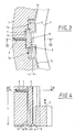
Figur 3- ausschnittsweise eine Draufsicht auf die Optik-Fassung
nach der
Figur 1 mit einem Querschnitt in Höhe eines Verstellgliedes eines Antriebs nach der Linie III-III der Fig. 4; - Figur 4
- einen Schnitt nach der Linie IV-IV der
Figur 3; Figur 5- ausschnittsweise eine Draufsicht auf eine weitere Ausführungsform im Bereich der Festkörperdrehgelenke.
- Figure 1
- an optical socket as an adjustable assembly in plan view;
- Figure 2
- a schematic representation of a solid body hinge as a lever gear with a rocker arm;
- Figure 3
- Detail of a plan view of the optical mount according to Figure 1 with a cross section at the level of an adjusting member of a drive along the line III-III of Fig. 4;
- Figure 4
- a section along the line IV-IV of Figure 3;
- Figure 5
- a section of a plan view of a further embodiment in the area of the solid-body rotary joints.
Die in der Figur 1 prinzipmäßig dargestellte Optik-Fassung
weist als Fassung einen Fassungsring 1 auf, der über drei Festkörpergelenke
2 mit einem Innenring 3 verbunden ist. Der Fassungsring
1 und der Innenring 3 können einstückig ausgebildet
sein. Der Innenring 3 trägt als optisches Element eine Linse 4.The optics frame shown in principle in Figure 1
has a
Durch die Verbindung des Flanschringes 1 mit dem Innenring 3,
auf dem die Linse 4 montiert ist, wird über die drei Festkörpergelenke
2 eine Spannungsentkoppelung erreicht.By connecting the
Eine Verstellmöglichkeit wird nun dadurch geschaffen, daß ein
oder mehrere Festkörpergelenke 2 in Form eines Hebelgetriebes
ausgebildet werden, das im wesentlichen aus einem Kipphebel 5
besteht. Wie aus der Figur 2 ersichtlich ist, greift ein in den
Figuren 3 bis 5 dargestelltes Antriebsglied 6 als Manipulator
bzw. Antrieb an einem Ende des Kipphebels 5, der eine L-Form
aufweist, an.An adjustment is now created in that a
or several solid-
Durch den Kipphebel 5 wird eine Übersetzung l/L und eine Umkehr
der Bewegungsrichtung aus der x-Richtung in die z-Richtung
(optische Achse) erreicht. Wie ersichtlich, hängt somit das
Übersetzungsverhältnis unter anderem davon ab, wie klein der
Hebelarm l gemacht werden kann. Auf welche Weise dies erreicht
werden kann ist aus den Figuren 3 bis 5 erkennbar, wozu eines
oder mehrere der in der Figur 1 schematisch dargestellten Festkörpergelenke
2 entsprechend als Hebelgetriebe mit zwei Festkörperdrehgelenken
7 und 8 ausgebildet ist, wobei das Festkörperdrehgelenk
7 in zwei Drehgelenkteile 7a und 7b aufgeteilt
ist, die entlang ihrer Drehachse 9 seitlich versetzt beidseits
des dazwischenliegenden Festkörperdrehgelenkes 8 angeordnet
sind. Die Festkörperdrehgelenke 7 und 8 sind parallel orientiert
und entsprechend elastisch, um eine Verstellmöglichkeit
zu ergeben.Through the
Das Festkörperdrehgelenk 7 mit den beiden Drehgelenkteilen 7a
und 7b ist außenseitig mit dem Fassungsring 1 verbunden. Ein
Schlitz 10 in U-Form stellt eine Trennung des Kipphebels 5 von
dem Fassungsring 1 dar. Am oberen Ende des Kipphebels 5 greift
über den Schlitz 10 das Antriebsglied 6 an dem Kipphebel 5 an.The solid body hinge 7 with the two
Das Festkörperdrehgelenk 8 ist innenseitig mit dem Innenring 3
verbunden und außenseitig am unteren Ende, d.h. an dem von dem
Angriffspunkt des Antriebsgliedes 6 abgewandten Ende an dem
Kipphebel 5 angelenkt. Durch einen umlaufenden Schlitz 11, der
nur durch die Festkörperdrehgelenke 7 bzw. 8 unterbrochen ist,
erfolgt die Entkoppelung des Innenringes 3 von dem Fassungsring
1.The solid
Wie aus den Figuren 3 und 4 ersichtlich ist, können die Festkörperdrehgelenke
7 und 8 aufgrund der Aufteilung des Festkörperdrehgelenkes
7 in die beiden Drehgelenkteile 7a und 7b deutlich
näher zueinander gerückt werden, als dies im Vergleich zu
einer nicht aufgeteilten Form möglich wäre. Das Maß l kann entsprechend
kleiner gewählt werden, so daß das Übersetzungsverhältnis
l/L bei einer Betätigung des Antriebsgliedes 6 durch
einen nicht näher dargestellten Antrieb zur Verschiebung des
Innenringes 3 und damit des optischen Elements 4 in z-Richtung
sehr groß bzw. feinfühlig wird. As can be seen from FIGS. 3 and 4, the solid-state swivel joints can
7 and 8 due to the division of the solid body hinge
7 clearly in the two
Soll das Übersetzungsverhältnis nochmals erhöht werden, so läßt sich dies mit einer Ausgestaltung nach der Figur 5 erreichen.If the gear ratio is to be increased again, then let this can be achieved with an embodiment according to FIG. 5.
Wie ersichtlich, ist dabei zwischen dem Antriebsglied 6 und dem
Kipphebel 5 eine weitere Hebelübersetzung mit einem Hebel 12
angeordnet. Der Hebel 12 ist an einem Ende als Lagerungsstelle
über ein elastisches Festkörperdrehgelenk 13 mit dem Fassungsring
1 verbunden, während ansonsten der Hebel 12 über einen
Schlitz 14 von dem Fassungsring 1 getrennt ist. Der Schlitz 14
muß selbstverständlich eine derartige Breite besitzen, daß bei
einer Betätigung durch das Antriebsglied 6 entsprechende Bewegungen
des Hebels 12 möglich sind. An dem von dem Ende mit dem
Festkörperdrehgelenk 13 abgewandten Endbereich greift das Antriebsglied
6 an. Die weitere Hebelübersetzung ist damit monolitisch
bzw. einstückig mit der Fassung 1. Über eine Verbindungsstelle
15 in Form eines Zwischenarmes ist der Hebel mit
dem Kipphebel 5 verbunden. Um die Übersetzungserhöhung zu erreichen,
wird man die Verbindungsstelle 15 näher an dem Ende
mit dem Festkörperdrehgelenk 13 als an dem Angriffspunkt des
Antriebsgliedes 6 anordnen. Die Höhe der Übersetzung richtet
sich dabei nach den gewählten Abständen.As can be seen, is between the
Selbstverständlich kann die Verbindungsstelle 15 auch anders
ausgebildet sein. Dies gilt z.B. für die Angriffsdrehrichtung
und dessen LageOf course, the
Bei Betätigung des Betätigungsgliedes 6 erfährt der Hebel 12
eine entsprechende Auslenkung, wobei die Auslenkkraft - entsprechend
übersetzt - über die Verbindungsstelle 15 auf den
Kipphebel 5 weitergeleitet wird, womit in bekannter Weise entsprechend
dem Ausführungsbeispiel nach den Figuren 3 und 4 eine
Verschiebung des optischen Elements 4 in z-Richtung, d.h. in
Richtung der optischen Achse erfolgt. Auf diese Weise kann ein
verkipptes optisches Element wieder in die Soll-Lage zurückgekippt
werden.When the
Claims (11)
Applications Claiming Priority (2)
| Application Number | Priority Date | Filing Date | Title |
|---|---|---|---|
| DE19908554A DE19908554A1 (en) | 1999-02-27 | 1999-02-27 | Adjustable assembly |
| DE19908554 | 1999-02-27 |
Publications (2)
| Publication Number | Publication Date |
|---|---|
| EP1031996A2 true EP1031996A2 (en) | 2000-08-30 |
| EP1031996A3 EP1031996A3 (en) | 2001-03-28 |
Family
ID=7899090
Family Applications (1)
| Application Number | Title | Priority Date | Filing Date |
|---|---|---|---|
| EP00103667A Withdrawn EP1031996A3 (en) | 1999-02-27 | 2000-02-22 | Adjustable assembly |
Country Status (6)
| Country | Link |
|---|---|
| US (1) | US6259571B1 (en) |
| EP (1) | EP1031996A3 (en) |
| JP (1) | JP4489894B2 (en) |
| KR (1) | KR100628410B1 (en) |
| DE (1) | DE19908554A1 (en) |
| TW (1) | TW538262B (en) |
Cited By (5)
| Publication number | Priority date | Publication date | Assignee | Title |
|---|---|---|---|---|
| EP1035426A2 (en) * | 1999-03-12 | 2000-09-13 | Carl Zeiss | Device for moving an optical element along the optical axis |
| WO2008009276A1 (en) * | 2006-07-21 | 2008-01-24 | Jenoptik Laser, Optik, Systeme Gmbh | Laterally adjustable socket for optical elements |
| WO2010072217A1 (en) * | 2008-12-23 | 2010-07-01 | Jenoptik Laser, Optik, Systeme Gmbh | Monolithic optical mount |
| EP2255237A4 (en) * | 2008-02-29 | 2013-01-23 | Corning Inc | Kinematic optical mount |
| EP2927725A3 (en) * | 2014-03-11 | 2016-01-13 | Ruag Space GmbH | Positioning device for space flight applications |
Families Citing this family (31)
| Publication number | Priority date | Publication date | Assignee | Title |
|---|---|---|---|---|
| JP4945845B2 (en) | 2000-03-31 | 2012-06-06 | 株式会社ニコン | An optical element holding device, a lens barrel, an exposure apparatus, and a microdevice manufacturing method. |
| WO2001081970A2 (en) * | 2000-04-25 | 2001-11-01 | Silicon Valley Group, Inc. | Apparatus, system, and method for precision positioning and alignment of a lens in an optical system |
| JP4518630B2 (en) * | 2000-06-20 | 2010-08-04 | 株式会社タムロン | Lens barrel |
| DE10030495A1 (en) | 2000-06-21 | 2002-01-03 | Zeiss Carl | Method for connecting a plurality of optical elements to a base body |
| US6574053B1 (en) | 2000-08-10 | 2003-06-03 | Nikon Corporation | Kinematic alignment structure for placement between components axially aligned in a cylindrical body |
| KR100775796B1 (en) * | 2000-08-18 | 2007-11-12 | 가부시키가이샤 니콘 | Optical element holding device |
| DE10051706A1 (en) | 2000-10-18 | 2002-05-02 | Zeiss Carl | Device for supporting optical element, has approximately T-shaped joints with connection points between holders at outer ends of T-bearer and manipulators engaging T-support |
| US6417976B1 (en) * | 2001-03-06 | 2002-07-09 | Terabeam Corporation | Apparatus and method to mount electro-optic systems |
| JP2002287023A (en) | 2001-03-27 | 2002-10-03 | Nikon Corp | Projection optical system, projection aligner equipped with projection optical system, and projection aligning method |
| DE10115915A1 (en) * | 2001-03-30 | 2002-10-02 | Zeiss Carl | Device for adjusting devices and adjusting adjustment paths |
| DE10136387A1 (en) * | 2001-07-26 | 2003-02-13 | Zeiss Carl | Optical objective for semiconductor lithography has optical element with reflective reference surface used for adjustment relative to objective |
| DE10140608A1 (en) * | 2001-08-18 | 2003-03-06 | Zeiss Carl | Device for adjusting an optical element |
| DE10219514A1 (en) * | 2002-04-30 | 2003-11-13 | Zeiss Carl Smt Ag | Lighting system, especially for EUV lithography |
| JP4665759B2 (en) † | 2003-06-06 | 2011-04-06 | 株式会社ニコン | Optical element holding device, lens barrel, exposure apparatus, and device manufacturing method |
| DE10331390A1 (en) | 2003-07-11 | 2005-01-27 | Carl Zeiss Smt Ag | Aspherical surface production process for optical elements, comprises placing element in mould, introducing medium, and spherically working deformed optical medium |
| US6816325B1 (en) | 2003-09-11 | 2004-11-09 | Carl Zeiss Smt Ag | Mounting apparatus for an optical element |
| DE10344178B4 (en) * | 2003-09-24 | 2006-08-10 | Carl Zeiss Smt Ag | Holding and positioning device for an optical element |
| US7265917B2 (en) * | 2003-12-23 | 2007-09-04 | Carl Zeiss Smt Ag | Replacement apparatus for an optical element |
| US7697222B2 (en) * | 2003-12-25 | 2010-04-13 | Nikon Corporation | Apparatus for holding optical element, barrel, exposure apparatus, and device producing method |
| US7612956B2 (en) * | 2007-02-28 | 2009-11-03 | Corning Incorporated | Optical mount pivotable about a single point |
| DE102007014155A1 (en) * | 2007-03-20 | 2008-09-25 | Jenoptik Laser, Optik, Systeme Gmbh | Optics socket and optical component with such an optical socket |
| DE102008000967B4 (en) * | 2008-04-03 | 2015-04-09 | Carl Zeiss Smt Gmbh | Projection exposure machine for EUV microlithography |
| JP5935975B2 (en) * | 2011-11-14 | 2016-06-15 | 株式会社ニコン | Optical member position adjusting device, projection optical system, adjusting method thereof, and exposure apparatus |
| CN103472555B (en) * | 2013-09-25 | 2016-06-01 | 中国科学院长春光学精密机械与物理研究所 | Dual-motor optical element axial adjustment device |
| DE102015101385B3 (en) * | 2015-01-30 | 2016-01-21 | Jenoptik Optical Systems Gmbh | Optical socket with at least one clamping unit with a lag screw |
| DE102015101384B3 (en) * | 2015-01-30 | 2015-11-12 | Jenoptik Optical Systems Gmbh | Optical socket with at least one clamping unit with a pressure screw |
| DE102015101387B3 (en) * | 2015-01-30 | 2015-12-17 | Jenoptik Optical Systems Gmbh | Optical socket with at least one clamping unit with a diaphragm spring |
| CN104749734B (en) * | 2015-03-24 | 2017-04-05 | 中国科学院长春光学精密机械与物理研究所 | A kind of optical element axial location precision adjustment unit |
| DE102015115929B3 (en) * | 2015-09-21 | 2016-10-06 | Jenoptik Optical Systems Gmbh | Monolithic lens frame |
| DE102015223518A1 (en) * | 2015-11-27 | 2017-05-18 | Carl Zeiss Smt Gmbh | Optical device and lithography system |
| JP7373853B2 (en) * | 2018-06-08 | 2023-11-06 | 株式会社nittoh | Lens barrel and interchangeable lens camera |
Citations (6)
| Publication number | Priority date | Publication date | Assignee | Title |
|---|---|---|---|---|
| DD278207A1 (en) * | 1988-12-19 | 1990-04-25 | Zeiss Jena Veb Carl | ASSEMBLY WITH ADJUSTING ELEMENTS |
| WO1992002837A1 (en) * | 1990-08-02 | 1992-02-20 | British Telecommunications Public Limited Company | Optical component holder |
| US5428482A (en) * | 1991-11-04 | 1995-06-27 | General Signal Corporation | Decoupled mount for optical element and stacked annuli assembly |
| JPH1054932A (en) * | 1996-08-08 | 1998-02-24 | Nikon Corp | Projection optical device and projection exposure device provided the device |
| JPH10186198A (en) * | 1996-12-25 | 1998-07-14 | Ushio Inc | Parallel and straight fine adjustment device and fine moving device of lens barrel using the same |
| DE19827603A1 (en) * | 1998-06-20 | 1999-12-23 | Zeiss Carl Fa | Projection light exposure system for microlithography |
Family Cites Families (4)
| Publication number | Priority date | Publication date | Assignee | Title |
|---|---|---|---|---|
| JPS58111908A (en) * | 1981-12-25 | 1983-07-04 | Canon Inc | Lens holder of lens barrel for optical apparatus |
| NL8500615A (en) * | 1985-03-05 | 1986-10-01 | Nederlanden Staat | FINE ADJUSTMENT MECHANISM FOR PRECISE POSITIONING OF AN ADJUSTMENT ELEMENT. |
| JPS62147413A (en) * | 1985-12-20 | 1987-07-01 | Olympus Optical Co Ltd | Lens holding device |
| EP0932064A1 (en) | 1997-12-29 | 1999-07-28 | Perkin-Elmer Limited | Adjustable mounting of optical components |
-
1999
- 1999-02-27 DE DE19908554A patent/DE19908554A1/en not_active Ceased
-
2000
- 2000-02-14 US US09/503,023 patent/US6259571B1/en not_active Expired - Lifetime
- 2000-02-22 KR KR1020000008429A patent/KR100628410B1/en not_active IP Right Cessation
- 2000-02-22 EP EP00103667A patent/EP1031996A3/en not_active Withdrawn
- 2000-02-24 JP JP2000047169A patent/JP4489894B2/en not_active Expired - Fee Related
- 2000-04-25 TW TW089103354A patent/TW538262B/en not_active IP Right Cessation
Patent Citations (6)
| Publication number | Priority date | Publication date | Assignee | Title |
|---|---|---|---|---|
| DD278207A1 (en) * | 1988-12-19 | 1990-04-25 | Zeiss Jena Veb Carl | ASSEMBLY WITH ADJUSTING ELEMENTS |
| WO1992002837A1 (en) * | 1990-08-02 | 1992-02-20 | British Telecommunications Public Limited Company | Optical component holder |
| US5428482A (en) * | 1991-11-04 | 1995-06-27 | General Signal Corporation | Decoupled mount for optical element and stacked annuli assembly |
| JPH1054932A (en) * | 1996-08-08 | 1998-02-24 | Nikon Corp | Projection optical device and projection exposure device provided the device |
| JPH10186198A (en) * | 1996-12-25 | 1998-07-14 | Ushio Inc | Parallel and straight fine adjustment device and fine moving device of lens barrel using the same |
| DE19827603A1 (en) * | 1998-06-20 | 1999-12-23 | Zeiss Carl Fa | Projection light exposure system for microlithography |
Non-Patent Citations (2)
| Title |
|---|
| PATENT ABSTRACTS OF JAPAN vol. 1998, no. 06, 30. April 1998 (1998-04-30) & JP 10 054932 A (NIKON CORP), 24. Februar 1998 (1998-02-24) * |
| PATENT ABSTRACTS OF JAPAN vol. 1998, no. 12, 31. Oktober 1998 (1998-10-31) & JP 10 186198 A (USHIO INC), 14. Juli 1998 (1998-07-14) * |
Cited By (7)
| Publication number | Priority date | Publication date | Assignee | Title |
|---|---|---|---|---|
| EP1035426A2 (en) * | 1999-03-12 | 2000-09-13 | Carl Zeiss | Device for moving an optical element along the optical axis |
| EP1035426A3 (en) * | 1999-03-12 | 2004-06-30 | Carl Zeiss | Device for moving an optical element along the optical axis |
| WO2008009276A1 (en) * | 2006-07-21 | 2008-01-24 | Jenoptik Laser, Optik, Systeme Gmbh | Laterally adjustable socket for optical elements |
| EP2255237A4 (en) * | 2008-02-29 | 2013-01-23 | Corning Inc | Kinematic optical mount |
| WO2010072217A1 (en) * | 2008-12-23 | 2010-07-01 | Jenoptik Laser, Optik, Systeme Gmbh | Monolithic optical mount |
| US8547652B2 (en) | 2008-12-23 | 2013-10-01 | Jenoptik Optical Systems Gmbh | Monolithic optical mount |
| EP2927725A3 (en) * | 2014-03-11 | 2016-01-13 | Ruag Space GmbH | Positioning device for space flight applications |
Also Published As
| Publication number | Publication date |
|---|---|
| KR100628410B1 (en) | 2006-09-28 |
| JP2000249886A (en) | 2000-09-14 |
| US6259571B1 (en) | 2001-07-10 |
| TW538262B (en) | 2003-06-21 |
| DE19908554A1 (en) | 2000-08-31 |
| KR20010014500A (en) | 2001-02-26 |
| JP4489894B2 (en) | 2010-06-23 |
| EP1031996A3 (en) | 2001-03-28 |
Similar Documents
| Publication | Publication Date | Title |
|---|---|---|
| EP1031996A2 (en) | Adjustable assembly | |
| EP1020751B1 (en) | Optical imaging device, especially lens, with at least one optical element | |
| DE3829022C2 (en) | ||
| EP1182485B1 (en) | Apparatus for adjusting the relative positions of two elements | |
| EP1577693B1 (en) | Objective comprising at least one optical element | |
| DE102009037135A1 (en) | Holding device for an optical element | |
| EP0169363B1 (en) | Device, in particular a travelling wiping device for automotive vehicles | |
| DE4226506B4 (en) | Steering column switch for motor vehicles | |
| DE19955984A1 (en) | Optical imaging device, in particular objective with at least one system aperture | |
| DE102012100461A1 (en) | Adjustment device for light modules of a vehicle | |
| DE3048384C2 (en) | Switch component for an overhead conveyor | |
| DE102013109605B3 (en) | Optical assembly of monolithic frame, has adjustable screw that is fed by through hole in outer ring and nut portion that is connected by second bar with inner ring | |
| EP1485762A2 (en) | Device for manipulation of the angular position of an object relative to a fixed structure | |
| EP1762774B1 (en) | Headlamp | |
| DE19947174A1 (en) | Mask holder with clamps on disc-shaped frame for exposure of semiconductor wafers in ion lithography | |
| DE60201429T2 (en) | MOUNTING AND ADJUSTMENT DEVICE SET UP IN THE SHADE OF A MIRROR FOR THIS MIRROR AND OPTICAL SYSTEM THAT HAS SUCH A MECHANISM | |
| DE4118325C2 (en) | Variable focal length viewfinder | |
| WO2006045264A1 (en) | Device for adjusting an optical fiber or an optical fiber bundle | |
| EP1375989B1 (en) | Piezoelectric valve | |
| DE10004661B4 (en) | Device for pivoting a light beam | |
| EP0447918B1 (en) | Tolerance deviation compensation device | |
| DE102007028402B4 (en) | Microscope and anti-jamming device for a microscope | |
| DE19951997C2 (en) | Optical device with an image stabilizer | |
| DE102011012388B3 (en) | Adjuster for alignment of laser collimator utilized for emitting laser line or laser spot, has bars connected with sides of base part and carrier component such that twist of component is enabled | |
| DE19539581B4 (en) | Universal joint with spring four joints |
Legal Events
| Date | Code | Title | Description |
|---|---|---|---|
| PUAI | Public reference made under article 153(3) epc to a published international application that has entered the european phase |
Free format text: ORIGINAL CODE: 0009012 |
|
| AK | Designated contracting states |
Kind code of ref document: A2 Designated state(s): DE FR GB IT NL |
|
| AX | Request for extension of the european patent |
Free format text: AL;LT;LV;MK;RO;SI |
|
| RIN1 | Information on inventor provided before grant (corrected) |
Inventor name: TRUNZ, MICHAEL Inventor name: POST, ALBERT, C/O PHILIPS CFT-MECHATRONICS Inventor name: TIMMERS, HUGO, C/O PHILIPS CFT-MECHATRONICS Inventor name: POLZER, THOMAS Inventor name: HOLDERER, HUBERT Inventor name: DRIES, JOHAN, C/O PHILIPS CFT-MECHATRONICS Inventor name: RUEMMER, PETER Inventor name: GEUPPERT, BERNHARD |
|
| K1C1 | Correction of patent application (title page) published |
Effective date: 20000830 |
|
| RIN1 | Information on inventor provided before grant (corrected) |
Inventor name: TIMMERS, HUGO, C/O PHILIPS CFT-MECHATRONICS Inventor name: DRIES, JOHAN, C/O PHILIPS CFT-MECHATRONICS Inventor name: POLZER, THOMAS Inventor name: POST, ALBERT, C/O PHILIPS CFT-MECHATRONICS Inventor name: HOLDERER, HUBERT Inventor name: TRUNZ, MICHAEL Inventor name: GEUPPERT, BERNHARD Inventor name: RUEMMER, PETER |
|
| PUAL | Search report despatched |
Free format text: ORIGINAL CODE: 0009013 |
|
| AK | Designated contracting states |
Kind code of ref document: A3 Designated state(s): AT BE CH CY DE DK ES FI FR GB GR IE IT LI LU MC NL PT SE |
|
| AX | Request for extension of the european patent |
Free format text: AL;LT;LV;MK;RO;SI |
|
| RIC1 | Information provided on ipc code assigned before grant |
Free format text: 7G 12B 5/00 A, 7G 02B 7/02 B |
|
| 17P | Request for examination filed |
Effective date: 20010626 |
|
| AKX | Designation fees paid |
Free format text: DE FR GB IT NL |
|
| RAP1 | Party data changed (applicant data changed or rights of an application transferred) |
Owner name: CARL ZEISS SMT AG |
|
| 17Q | First examination report despatched |
Effective date: 20070807 |
|
| RAP1 | Party data changed (applicant data changed or rights of an application transferred) |
Owner name: CARL ZEISS SMT AG |
|
| GRAP | Despatch of communication of intention to grant a patent |
Free format text: ORIGINAL CODE: EPIDOSNIGR1 |
|
| STAA | Information on the status of an ep patent application or granted ep patent |
Free format text: STATUS: THE APPLICATION IS DEEMED TO BE WITHDRAWN |
|
| 18D | Application deemed to be withdrawn |
Effective date: 20081111 |