EP1031217B1 - Verfahren und vorrichtung zur optimierung von shelldarstellungstechniken mit angenäherter stromkostfunktion - Google Patents
Verfahren und vorrichtung zur optimierung von shelldarstellungstechniken mit angenäherter stromkostfunktion Download PDFInfo
- Publication number
- EP1031217B1 EP1031217B1 EP98957827A EP98957827A EP1031217B1 EP 1031217 B1 EP1031217 B1 EP 1031217B1 EP 98957827 A EP98957827 A EP 98957827A EP 98957827 A EP98957827 A EP 98957827A EP 1031217 B1 EP1031217 B1 EP 1031217B1
- Authority
- EP
- European Patent Office
- Prior art keywords
- log
- ring
- mapping
- cost function
- tuples
- Prior art date
- Legal status (The legal status is an assumption and is not a legal conclusion. Google has not performed a legal analysis and makes no representation as to the accuracy of the status listed.)
- Expired - Lifetime
Links
Images


Classifications
-
- H—ELECTRICITY
- H04—ELECTRIC COMMUNICATION TECHNIQUE
- H04L—TRANSMISSION OF DIGITAL INFORMATION, e.g. TELEGRAPHIC COMMUNICATION
- H04L25/00—Baseband systems
- H04L25/38—Synchronous or start-stop systems, e.g. for Baudot code
- H04L25/40—Transmitting circuits; Receiving circuits
- H04L25/49—Transmitting circuits; Receiving circuits using code conversion at the transmitter; using predistortion; using insertion of idle bits for obtaining a desired frequency spectrum; using three or more amplitude levels ; Baseband coding techniques specific to data transmission systems
- H04L25/4917—Transmitting circuits; Receiving circuits using code conversion at the transmitter; using predistortion; using insertion of idle bits for obtaining a desired frequency spectrum; using three or more amplitude levels ; Baseband coding techniques specific to data transmission systems using multilevel codes
- H04L25/4927—Transmitting circuits; Receiving circuits using code conversion at the transmitter; using predistortion; using insertion of idle bits for obtaining a desired frequency spectrum; using three or more amplitude levels ; Baseband coding techniques specific to data transmission systems using multilevel codes using levels matched to the quantisation levels of the channel
Definitions
- the present invention generally relates to shell mapping schemes used in the transmission of digital information over an analog medium connected to a digital network, particularly in the context of Pulse Code Modulation (PCM) modems. More specifically, the present invention relates to a mapping scheme for maximizing transmitting power efficiency while substantially limiting the complexity of the shell mapping.
- PCM modems There has been much recent development of high-speed communications technology based on PCM modems, where data rates of at least 56 kbps are said to be actually attainable.
- the PCM modem technology is based on the simple realization that the PSTN is increasingly a digital network and not an analog network. Also, more and more central site modems are connected to the PSTN through digital connections. i.e.. T1 in the U.S. and E1 in Europe, without requiring a CODEC (coder/decoder).
- a CODEC is a device which connects the digital portion of the network to the analog local loop and converts between analog and digital.
- central site modems refer to those modems installed at an ISP, or at a corporation. for example, to allow many simultaneous connections for remote local area network (LAN) access.
- LAN local area network
- the recent 56 kbps technology seeks to address an impaired section of the communications path of the PSTN digital network, where the impairment is due to the hybrid and the copper wire interface between the telephone central office and the user's home, usually referred to as the analog local loop.
- PCM modems Since recently, much has been described about PCM modems and how they can and should facilitate downstream data communication at a much higher rate than the present paradigm.
- PCM modem has been the subject of a recent Telecommunications Industry Association (TIA) Technical Committee TR-30 Standards meeting on October 16-17, 1996.
- TAA Telecommunications Industry Association
- the submitted technical contributions include Guozhu Long's DC Suppressor for 56K Modems, Guozhu Long's Two-Step Mapping for 56K Modems, David C.
- Another U.S. patent also issued to Ender Ayanoglu of AT&T, U.S. Patent No. 5.394.437, dated Feb. 28, 1995 entitled High-Speed Modem Synchronized To A Remote CODEC discloses a high-speed modem for data transmission over an analog medium in tandem with a digital network.
- FIG. 1 depicts a conceptual diagram of the typical high-speed communication path using PCM modem technology.
- An ISP, or central site, 100 is digitally connected to a telephone network 130 through a transmitter 110 and a receiver 120 of an ISP modem 105.
- the network 130 is connected to a local loop 150 through a central office line card 140.
- the line card typically has a PCM CODEC implemented therein.
- the local loop 150 is connected to the user's PC at the user's site through the user's modem 160.
- the connection between the ISP modem transmitter 110 to the telephone network 130 is a digital connection with a typical data rate of about 64 kbps.
- the central site transmitter 110 needs to transmit the digital data in a particular way to fully exploit its digital connection to the network.
- ⁇ -law constellations, shell mapping, and PCM-based modem systems in this new paradigm has some obstacles.
- the shell mapping algorithm is essentially designed to select ring indices in a manner which minimizes average transmission power based on, inter alia, the assumption that the average power of each ring is approximately proportional to its ring index, and based on the further assumption that any particular constellation can be scaled to meet the transmit power level requirement.
- the signal points are selected from a fixed, non-uniformly spaced set of levels determined by the PCM codec in accordance with the well-known ⁇ -law algorithm.
- the coding component often involves error-correction coding, whereas the mapping component strives to minimize the transmission power in view of the restraints imposed by the coding process.
- the traditional V.34 coding function involves the use of convolutional trellis codes, whereas the mapping is in the form of shell mapping.
- the shell mapping algorithm employed in V.34 is one of the more complex functions in a V.34 modem.
- V.34 Recommendation see ITU-T Recommendation V.34, published September 1994 by the International Telecommunication Union, the entire contents of which is hereby incorporated by this reference.
- the V.34 encoding algorithm takes a block of bits corresponding to a mapping frame of eight (8) symbols, and maps a part of that block to a set of eight (8) ring indices, which are used to determine a subset of the constellation from which the transmitted signal points are selected.
- the subsets are, as the name indicates, in the form of concentric rings around the origin.
- the energy of the signal points in a given ring is within a certain range, which energy range increases with increasing distance from the origin.
- the index of the ring is a fairly accurate approximation of the contribution to signal power of a point in that ring.
- the V.34 shell mapping algorithm uses this simple relationship to select sets of ring indices where the sum of the indices is the smallest. Sets of ring indices with higher sums tend to be omitted, thus optimizing transmit power.
- the innermost rings are selected most often, and the outermost rings are selected least often.
- the signal points are selected from a non-uniform set of levels determined by the ⁇ -law algorithm. Many of the characteristics of the V.34 constellation are therefore lost in a PCM modem context, for example the linear relationship between ring index and that ring's contribution to transmission power.
- the present invention provides methods and apparatus for implementing a shell mapping algorithm in the context of a PCM modem in accordance with the claims which follow.
- the transmitting power efficiency is substantially maximized while substantially limiting the complexity of the mapping.
- the present invention suitably calculates an approximate cost function g ( n ) and suitably determines the 2 K lowest cost N -tuples ( m 0 ,m 1 , etc m N-1 ). Knowing the lowest cost N -tuples, fractional K data bits are systematically mapped uniformily onto the 2 K lowest cost N-tuples, thereby achieving optimum power efficiency.
- an exemplary shell mapping apparatus having an input means for receiving digital data, a means. for determining the lowest cost rings in accordance with an approximated cost function 2 n , and an output means for mapping these ring indices onto the digital data.
- a shell mapping algorithm is suitably performed such that power transmitting efficiency is substantially maximized while the computational complexity associated with the mapping procedure is substantially minimized.
- N is set to eight, and a method of deriving the lowest cost 8-tuples is provided in accordance with the present invention.
- an exemplary PCM-based modem transmitter 110 suitably comprises a signal point encoder 202.
- signal point encoder 202 comprises a shell mapper 204, a reordering look up table 206, a mapping block 208, a spectrum control circuit 210, and a polarity block 212.
- shell mapper 204 reordering look up table 206
- mapping block 208 a mapping block 208
- spectrum control circuit 210 e.g., polarity block 212
- spectrum control 210 may suitably be implemented as one or a combination of discrete electronic components, integrated circuits, software modules, or any other convenient implementation.
- mapping frame may be illustrated as follows:
- an exemplary mapping frame useful in conjunction with the present invention comprises eight PCM samples per mapping frame. corresponding to a total of b bits.
- the first K bits of a mapping frame may be conveniently used for the shell mapper (with a zero inserted for low mapping frames), and the following b-K bits are suitably divided in eight equal parts with u bits in each part depending on such factors as data rate, redundancy level, and the like.
- a redundancy value of sixteen means that in one out of every sixteen samples, one bit is used for redundancy purposes.
- the first K bits of a mapping frame ( S 1 , S 2 , across S K ) are mapped into a set of N ring indices ( m 0 , m 1 , ...., m N -1 ) by shell mapper 204, where N is the mapping frame size.
- the frame size is chosen to be eight, and the first K bits of the mapping frame are mapped into a set of 8 ring indices ( m 0 , m 1 , etc m- ).
- the values Q j-1 , Q j-3 . Q j, u-1 will ultimately be chosen from a constellation of points which are partitioned into rings.
- each point within the 56 kbps signal constellation is also selected from the set of ⁇ -law values, and that each horizontal line in the constellation corresponds to a ring index ( m ).
- a ring index m
- the symmetry of the system is such that, if constellation point p k is a member of a ring, then p k is also a member of a ring.
- shell mapper 204 suitably maps the first K bits of a mapping frame into a set of eight ring indices ( m 0 , m 1 .... m- ).
- this mapping is performed in a manner which substantially optimizes a specific cost function.
- a cost function is derived which closely approximates an exact power cost function. yet remains relatively non-complex from a computational standpoint.
- the 2 K lowest cost 8-tuples ( m 0 , m 2 ,...,m- ) are then derived from this function. The manner in which this cost function is derived and implemented is described in detail below in conjunction with Figure 3.
- ring indices (m 1 , m 2 , ..., m -) via shell mapper 204, these indices are suitably applied to a reordering look up table 206.
- reordering might be employed as an additional step to further optimize performance, e.g., to allow optimum use of ring indices having signal points spaced apart by d min , while maintaining average transmission power within desired limits.
- Such ring reordering may be suitably arrived at through an iterative process which incrementally shifts the rings containing signal points separated by d min to progressively lower assignments (in terms of frequency of occurrence), until acceptable average power ranges are satisfied. In a preferred embodiment, where an optimized shell mapping algorithm is implemented as set forth below, this reordering step need not be performed.
- the ring indices output from module 206 (or, if no module 206 is used. the ring indices output from module 204) are suitably applied to a multiplier 216, which advantageously shifts the ring indices to the left by a desired number of bits, as is known in the art.
- the left-shifted, reordered ring indices are then summed with the mapping values (Q j,1 , Q j,2 , .., Q j,u-1 ) at summer 214.
- the output of summer 214, the signal point index is suitably applied to mapping module 208. wherein the appropriate signal values are selected. Given a table of signal points as in Table 2, the signal point index represents an index directly determining which signal point is selected from the table. More particularly, mapping module 208 suitably comprises a unique, predetermined signal constellation for each anticipated data rate.
- mapping module 208 Once the signal point indices values are mapped to the signal constellation points in mapping module 208, the output from module 208 is suitably applied to a multiplier 218, whereupon a polarity bit from polarity module 212 is combined with the output of mapping module 208 to ensure that the encoded signal output from multiplier 218 includes the appropriate polarity.
- Spectrum control unit 210 suitably controls the spectrum of the transmitted PCM signal by modifying the sign of every r th sample based on an objective function of C n , where:
- the metric C n is calculated for each output sample x n , and the sign of every r th sample is determined by considering C n . If C n is negative, the bit Q j,0 is set to zero and the outgoing sample is thus positive. If C n is positive or zero, Q j,0 is set to one and the outgoing sample becomes negative. In the preferred embodiment, a redundant-sign algorithm is used for spectrum control.
- the ⁇ -law PCM constellation comprises a total of 255 signal levels which are divided into sixteen segments, each segment comprising sixteen points.
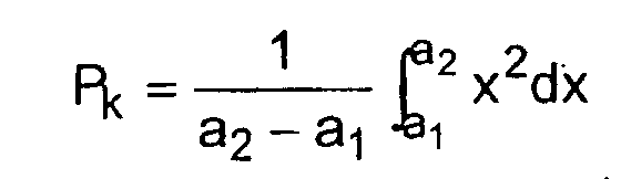
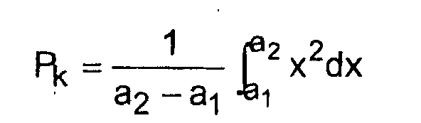
- an approximation of the mean power P in ring zero is can be expressed as:
- K data bits may be systematically mapped uniformly onto the 2 K lowest cost N -tuples ( m 0 , m 1 ?? m N-1 ), m ⁇ ⁇ 0HzM-1 ⁇ .
- a generating polynomial G ( x ) for the cost function g(n) is defined using the approximated cost function such that: where g 1 (i) is the number of single rings which have an associated cost i.
- g 4 (i) the number four-ring combinations equal to i . can be derived as: g 4 ( i )- g 2 (0) g 2 ( i )+ g 2 (1) g 2 ( i -1)+...+ g 2 ( i ) g 2 (0)
- the illustrated method may be easily modified by those skilled in the art to address larger or smaller frame sizes.
- the largest i is suitably determined such that z s (i) ⁇ x (Step 304), and R s is set equal to x - z s (i) (Step 306).
- i becomes the total cost of the 8-tuple.
- R 41 , R 42 , C 00 and C 01 are suitably defined.
- Steps 308-314 are preferably repeated with R 41 instead of R g , c 00 instead of i , and g 2 instead of g 4 , thereby suitably deriving values for R 211 , R 212 , c 1 and c 2 .
- Step 320 the term R 41 - g 2 (s)g 2 (c 00 - s ) is divided by g 2 ( s ) , and R 212 is set equal to the quotient and R 211 is set equal to the remainder.
- Steps 308-314 are preferably repeated with R 211 instead of R s , c 1 instead of i , and g 1 instead of g 4 .
- Steps 308-314 are preferably repeated with R 212 instead of R s , c 2 instead of i , and g 1 instead of g 4 .
- Steps 316-330 are suitably repeated using c 01 instead of c 00 in Steps 316-320.
- N e.g., N -6
- Opt1 curve 502 depicts the theoretically optimum ring probabilities with respect to power achievable assuming infinite framelength and exact values of ring energies.
- Opt2 curve 504 depicts the theoretically optimum ring probabilities with consideration for transmit power and assuming infinite framelength and approximate ring energies.
- Shell-mapper curve 506 depicts results in accordance with the method of the present invention wherein the framelength is set at eight and ring energies are approximated as set forth above.
- the present invention provides methods and apparatus for implementing an optimized shell mapping algorithm in the context of a PCM modem.
- the proposed shell mapping scheme results in near optimum performance and at the same time provides a computationally efficient, implementation.
Claims (18)
- Shell-Mapping-Verfahren, das die folgenden Schritte umfasst:dadurch gekennzeichnet, dass der Bestimmungsschritt die folgenden Schritte umfasst:Empfangen digitaler Daten in einer Shell-Mapping-Einrichtung (204);Bestimmen der niedrigsten Kosten-N-Tupel in Übereinstimmung mit einer approximierten Leistungs-Kosten-Funktion g(n), wobei N die Größe des Mapping-Rahmens ist; undAbbilden von K Datenbits (208) gleichmäßig auf einen Ausgang, der 2K niedrigste Kosten-N-Tupel enthält;wobei a2 = f(k + 1), a1 = f(k) und f(k) eine Exponentialfunktion von k ist.Unterteilen (330, 346) einer Impulscodemodulations-Konstellation in M Ringe, wovon jeder einem Ring k zugeordnet ist; undDefinieren der approximierten Leistungs-Kosten-Funktion, die dem k-ten Ring zugeordnet ist, zu
- Verfahren nach Anspruch 1, bei dem a1 = f(k) = (2k - 1)b, a2 = f(k + 1) = (2k+1 - 1)b und bei dem der Ring null bei einem Konstellationswert b endet.
- Verfahren nach Anspruch 1, derart, dass in einer weiteren Approximation die approximierte Leistungs-Kosten-Funktion, die einem k-ten Ring zugeordnet ist, so definiert ist, dass
- Verfahren nach Anspruch 3, bei dem a gleich zwei ist.
- Verfahren nach Anspruch 3, bei dem a gleich eins ist.
- Verfahren nach Anspruch 3, bei dem die approximierte Leistungs-Kosten-Funktion definiert ist zu g(n) = 2n und bei dem n ein Ringindex ist.
- Verfahren nach Anspruch 6, bei dem der Bestimmungsschritt ferner die folgenden Schritte umfasst:Ableiten einer Menge von Zwischenwerten cij in Übereinstimmung mit der approximierten Leistungs-Kosten-Funktion und der Größe N des Mapping-Rahmens, wobeiund
 Berechnen einer Menge niedrigster Kosten-N-Tupel (m0, m1, m2, ..., mN-1) in Übereinstimmung mit den Zwischenwerten cij, wobei m0 = log2(c11), m1 = log2(c12), ..., mN-2 = log2(CN/2, 1) und mN-1 = log2(cN/2, 2).
 - Verfahren nach Anspruch 7, bei dem:die Größe N des Mapping-Rahmens gleich 6 ist,der Ableitungsschritt eine Menge von Zwischenwerten c11, c12, c21, c22, c31 und c32 ableitet; undder Berechnungsschritt eine Menge niedrigster Kosten-6-Tupel (m0, m1, m2, ..., m5) berechnet, wobei m0 = log2(c11), m1 = log2(c12), m2 = log2(c21), m3 = log2(c22), m4 = log2(c31) und m5 = log2(c32).
- Verfahren nach Anspruch 8, bei dem:die Größe N des Mapping-Rahmens gleich 8 ist,der Ableitungsschritt eine Menge von Zwischenwerten c11, c12, c21, c22, c31, c32, c41 und c42 ableitet; undder Berechnungsschritt eine Menge niedrigster Kosten-8-Tupel (m0, m1, m2, ..., mN-1) berechnet, wobei m0 = log2(c11 ), m1 = log2(c12), m2 = log2(c21), m3 = log2(c23), m4 = log2(c31), m5 = log2(c32), m6 = log2(c41) und m7 = log2(c42).
- Shell-Mapping-Vorrichtung, die umfasst:dadurch gekennzeichnet, dass der Bestimmungsschritt die folgenden Schritte umfasst:eine Eingabeeinrichtung (204) zum Empfangen digitaler Daten;eine Einrichtung (206) zum Bestimmen der niedrigsten Kosten-N-Tupel in Übereinstimmung mit einer approximierten Leistungs-Kosten-Funktion g(n), wobei N die Größe des Mapping-Rahmens ist; undMittel zum Abbilden von K Datenbits (208) auf einen Ausgang, der 2K niedrigste Kosten-N-Tupel enthält;wobei die approximierte Leistungs-Kosten-Funktion, die einem k-ten Ring zugeordnet ist, definiert ist zu:Mittel zum Unterteilen (330, 346) einer Impulscodemodulations-Konstellation in M Ringe, wovon jeder einem Ring k zugeordnet ist; undwobei a2 = f(k + 1), a1 = f(k) und f(k) eine Exponentialfunktion von k ist.
- Vorrichtung nach Anspruch 10, bei der a1 = f(k) = (2k - 1)b, a2 = f(k + 1) = (2k+1 - 1)b und bei dem der Ring null bei einem Konstellationswert b endet.
- Vorrichtung nach Anspruch 10, bei der in der Bestimmungseinrichtung die approximierte Kosten-Leistungs-Funktion, der ein k-ter Ring zugeordnet ist, definiert ist zu:
- Vorrichtung nach Anspruch 12, bei der a gleich zwei ist.
- Vorrichtung nach Anspruch 12, bei der a gleich eins ist.
- Vorrichtung nach Anspruch 12, bei der die approximierte Kostenfunktion definiert ist zu g(n) = 2n und n ein Ringindex ist.
- Vorrichtung nach Anspruch 15, bei der die Einrichtung zum Bestimmen der niedrigsten Kosten-N-Tupel umfasst:eine Einrichtung zum Ableiten einer Menge von Zwischenwerten cij, in Übereinstimmung mit der approximierten Kostenfunktion und der Größe N des Mapping-Rahmens, wobeiund
 eine Einrichtung zum Berechnen einer Menge niedrigster Kosten-N-Tupel (m0, m1, m2, ..., mN-1) in Übereinstimmung mit den Zwischenwerten cij, wobei m0 = log2(c11), m1 = log2(c12), ..., mN-2 = log2(CN/2, 1) und mN-1 = log2(cN/2, 2).
 - Vorrichtung nach Anspruch 16, bei der die Größe N des Mapping-Rahmens gleich 6 ist.
- Vorrichtung nach Anspruch 16, bei der die Größe N des Mapping-Rahmens gleich 8 ist.
Applications Claiming Priority (3)
| Application Number | Priority Date | Filing Date | Title |
|---|---|---|---|
| US972960 | 1997-11-19 | ||
| US08/972,960 US6259742B1 (en) | 1996-12-04 | 1997-11-19 | Methods and apparatus for optimizing shell mapping techniques using an approximated power cost function |
| PCT/US1998/024050 WO1999026385A1 (en) | 1997-11-19 | 1998-11-12 | Methods and apparatus for optimizing shell mapping techniques using an approximated power cost function |
Publications (2)
| Publication Number | Publication Date |
|---|---|
| EP1031217A1 EP1031217A1 (de) | 2000-08-30 |
| EP1031217B1 true EP1031217B1 (de) | 2004-05-26 |
Family
ID=25520336
Family Applications (1)
| Application Number | Title | Priority Date | Filing Date |
|---|---|---|---|
| EP98957827A Expired - Lifetime EP1031217B1 (de) | 1997-11-19 | 1998-11-12 | Verfahren und vorrichtung zur optimierung von shelldarstellungstechniken mit angenäherter stromkostfunktion |
Country Status (4)
| Country | Link |
|---|---|
| US (1) | US6259742B1 (de) |
| EP (1) | EP1031217B1 (de) |
| DE (1) | DE69824200T2 (de) |
| WO (1) | WO1999026385A1 (de) |
Families Citing this family (3)
| Publication number | Priority date | Publication date | Assignee | Title |
|---|---|---|---|---|
| US6259742B1 (en) | 1996-12-04 | 2001-07-10 | Conexant Systems, Inc. | Methods and apparatus for optimizing shell mapping techniques using an approximated power cost function |
| WO2001059946A1 (en) * | 2000-02-10 | 2001-08-16 | Telogy Networks, Inc. | A generalized precoder for the upstream voiceband modem channel |
| US7251270B2 (en) * | 2000-06-20 | 2007-07-31 | Paradyne Corporation | Systems and methods for fractional bit rate encoding in a communication system |
Family Cites Families (10)
| Publication number | Priority date | Publication date | Assignee | Title |
|---|---|---|---|---|
| US5048056A (en) * | 1990-06-08 | 1991-09-10 | General Datacomm, Inc. | Method and apparatus for mapping an eight dimensional constellation of a convolutionally coded communication system |
| US5394437A (en) | 1992-10-20 | 1995-02-28 | At&T Corp. | High-speed modem synchronized to a remote CODEC |
| US5428641A (en) | 1993-07-23 | 1995-06-27 | Motorola, Inc. | Device and method for utilizing zero-padding constellation switching with frame mapping |
| US5528625A (en) | 1994-01-03 | 1996-06-18 | At&T Corp. | High speed quantization-level-sampling modem with equalization arrangement |
| US5465273A (en) | 1994-04-20 | 1995-11-07 | General Datacomm, Inc. | Modem utilizing parity and convolutional encoder feedback |
| AU701274B2 (en) | 1994-12-09 | 1999-01-21 | Brent Townshend | High speed communications system for analog subscriber connections |
| US6031873A (en) * | 1996-06-24 | 2000-02-29 | 3Com Corporation | Nested shell mapping |
| US5926505A (en) * | 1996-10-16 | 1999-07-20 | Cirrus Logic, Inc. | Device, system, and method for modem communication utilizing two-step mapping |
| US6259742B1 (en) | 1996-12-04 | 2001-07-10 | Conexant Systems, Inc. | Methods and apparatus for optimizing shell mapping techniques using an approximated power cost function |
| US5838724A (en) * | 1997-02-14 | 1998-11-17 | General Datacomm, Inc. | Spectral and power shaping mapper for high data rate signalling |
-
1997
- 1997-11-19 US US08/972,960 patent/US6259742B1/en not_active Expired - Fee Related
-
1998
- 1998-11-12 EP EP98957827A patent/EP1031217B1/de not_active Expired - Lifetime
- 1998-11-12 WO PCT/US1998/024050 patent/WO1999026385A1/en active IP Right Grant
- 1998-11-12 DE DE69824200T patent/DE69824200T2/de not_active Expired - Lifetime
Also Published As
| Publication number | Publication date |
|---|---|
| EP1031217A1 (de) | 2000-08-30 |
| US6259742B1 (en) | 2001-07-10 |
| DE69824200T2 (de) | 2006-08-17 |
| DE69824200D1 (de) | 2004-07-01 |
| WO1999026385A1 (en) | 1999-05-27 |
Similar Documents
| Publication | Publication Date | Title |
|---|---|---|
| US6226334B1 (en) | Methods and apparatus for implementing shell mapping techniques in the context of a PCM-based modem communication system | |
| US6173015B1 (en) | Device and method for precoding data signals for PCM transmission | |
| KR100383029B1 (ko) | 디지탈화된심볼을발생하는인코더 | |
| US5838724A (en) | Spectral and power shaping mapper for high data rate signalling | |
| US6084915A (en) | Signaling method having mixed-base shell map indices | |
| US6438158B1 (en) | Method and apparatus for implementing enhanced multiple modulus conversion techniques in a signal point mapping context | |
| US5818879A (en) | Device, system and method for spectrally shaping transmitted data signals | |
| KR100416888B1 (ko) | 최적화 전송 컨스텔레이션을 이용한 pcm 업스트림 전송시스템, 장치 및 방법 | |
| US5812602A (en) | System and device for, and method of, communicating according to a trellis code of baseband signals chosen from a fixed set of baseband signal points | |
| US6201836B1 (en) | Method and apparatus for combining a Trellis coding scheme with a pre-coding scheme for data signals | |
| EP1031217B1 (de) | Verfahren und vorrichtung zur optimierung von shelldarstellungstechniken mit angenäherter stromkostfunktion | |
| CN1830188B (zh) | 使用时频有界基函数传递数字信息的系统和方法 | |
| WO1998013977A1 (en) | Device, system and method for spectrally shaping transmitted data signals | |
| US6901107B1 (en) | Systems, methods, and computer program products for generating a digital impairment learning signal having low energy content at direct current and Nyquist frequencies | |
| US5995548A (en) | Signaling method using multiple modulus shell mapping | |
| US6687306B1 (en) | Constellation adjustment based on detected encoding and encoding conversion for modem connections | |
| WO1998039883A1 (en) | Signalling method using multiple modulus conversion and shell mapping | |
| KR100733013B1 (ko) | 비선형 코덱을 위한 프리코딩 | |
| KR20030010579A (ko) | 모뎀 전송 전력 조정 방법 및 장치 | |
| JP2001318697A (ja) | アップストリーム音声帯域モデムチャネルの一般化されたプリコーダ | |
| Tretter et al. | Mapping Data to Channel Symbol Frames by a Modulus Encoder | |
| MXPA00006427A (es) | Dispositivo y metodo para precodificar señales de datos para la transmision de pcm |
Legal Events
| Date | Code | Title | Description |
|---|---|---|---|
| PUAI | Public reference made under article 153(3) epc to a published international application that has entered the european phase |
Free format text: ORIGINAL CODE: 0009012 |
|
| 17P | Request for examination filed |
Effective date: 20000613 |
|
| AK | Designated contracting states |
Kind code of ref document: A1 Designated state(s): DE FI FR GB IT SE |
|
| 17Q | First examination report despatched |
Effective date: 20001228 |
|
| GRAP | Despatch of communication of intention to grant a patent |
Free format text: ORIGINAL CODE: EPIDOSNIGR1 |
|
| GRAS | Grant fee paid |
Free format text: ORIGINAL CODE: EPIDOSNIGR3 |
|
| GRAA | (expected) grant |
Free format text: ORIGINAL CODE: 0009210 |
|
| AK | Designated contracting states |
Kind code of ref document: B1 Designated state(s): DE FI FR GB IT SE |
|
| PG25 | Lapsed in a contracting state [announced via postgrant information from national office to epo] |
Ref country code: IT Free format text: LAPSE BECAUSE OF FAILURE TO SUBMIT A TRANSLATION OF THE DESCRIPTION OR TO PAY THE FEE WITHIN THE PRESCRIBED TIME-LIMIT;WARNING: LAPSES OF ITALIAN PATENTS WITH EFFECTIVE DATE BEFORE 2007 MAY HAVE OCCURRED AT ANY TIME BEFORE 2007. THE CORRECT EFFECTIVE DATE MAY BE DIFFERENT FROM THE ONE RECORDED. Effective date: 20040526 Ref country code: FI Free format text: LAPSE BECAUSE OF FAILURE TO SUBMIT A TRANSLATION OF THE DESCRIPTION OR TO PAY THE FEE WITHIN THE PRESCRIBED TIME-LIMIT Effective date: 20040526 |
|
| REG | Reference to a national code |
Ref country code: GB Ref legal event code: FG4D |
|
| REF | Corresponds to: |
Ref document number: 69824200 Country of ref document: DE Date of ref document: 20040701 Kind code of ref document: P |
|
| PG25 | Lapsed in a contracting state [announced via postgrant information from national office to epo] |
Ref country code: SE Free format text: LAPSE BECAUSE OF FAILURE TO SUBMIT A TRANSLATION OF THE DESCRIPTION OR TO PAY THE FEE WITHIN THE PRESCRIBED TIME-LIMIT Effective date: 20040826 |
|
| REG | Reference to a national code |
Ref country code: GB Ref legal event code: 732E |
|
| ET | Fr: translation filed | ||
| PLBE | No opposition filed within time limit |
Free format text: ORIGINAL CODE: 0009261 |
|
| STAA | Information on the status of an ep patent application or granted ep patent |
Free format text: STATUS: NO OPPOSITION FILED WITHIN TIME LIMIT |
|
| REG | Reference to a national code |
Ref country code: FR Ref legal event code: TP |
|
| 26N | No opposition filed |
Effective date: 20050301 |
|
| PGFP | Annual fee paid to national office [announced via postgrant information from national office to epo] |
Ref country code: DE Payment date: 20121121 Year of fee payment: 15 Ref country code: FR Payment date: 20121130 Year of fee payment: 15 |
|
| PGFP | Annual fee paid to national office [announced via postgrant information from national office to epo] |
Ref country code: GB Payment date: 20121120 Year of fee payment: 15 |
|
| GBPC | Gb: european patent ceased through non-payment of renewal fee |
Effective date: 20131112 |
|
| REG | Reference to a national code |
Ref country code: FR Ref legal event code: ST Effective date: 20140731 |
|
| REG | Reference to a national code |
Ref country code: DE Ref legal event code: R119 Ref document number: 69824200 Country of ref document: DE Effective date: 20140603 |
|
| PG25 | Lapsed in a contracting state [announced via postgrant information from national office to epo] |
Ref country code: DE Free format text: LAPSE BECAUSE OF NON-PAYMENT OF DUE FEES Effective date: 20140603 |
|
| PG25 | Lapsed in a contracting state [announced via postgrant information from national office to epo] |
Ref country code: FR Free format text: LAPSE BECAUSE OF NON-PAYMENT OF DUE FEES Effective date: 20131202 Ref country code: GB Free format text: LAPSE BECAUSE OF NON-PAYMENT OF DUE FEES Effective date: 20131112 |