EP1031208B1 - Network monitoring method for telecommunications network - Google Patents
Network monitoring method for telecommunications network Download PDFInfo
- Publication number
- EP1031208B1 EP1031208B1 EP98947583A EP98947583A EP1031208B1 EP 1031208 B1 EP1031208 B1 EP 1031208B1 EP 98947583 A EP98947583 A EP 98947583A EP 98947583 A EP98947583 A EP 98947583A EP 1031208 B1 EP1031208 B1 EP 1031208B1
- Authority
- EP
- European Patent Office
- Prior art keywords
- network
- performance
- network element
- normal
- profit
- Prior art date
- Legal status (The legal status is an assumption and is not a legal conclusion. Google has not performed a legal analysis and makes no representation as to the accuracy of the status listed.)
- Expired - Lifetime
Links
Images


Classifications
-
- H—ELECTRICITY
- H04—ELECTRIC COMMUNICATION TECHNIQUE
- H04L—TRANSMISSION OF DIGITAL INFORMATION, e.g. TELEGRAPHIC COMMUNICATION
- H04L41/00—Arrangements for maintenance, administration or management of data switching networks, e.g. of packet switching networks
- H04L41/06—Management of faults, events, alarms or notifications
- H04L41/069—Management of faults, events, alarms or notifications using logs of notifications; Post-processing of notifications
-
- H—ELECTRICITY
- H04—ELECTRIC COMMUNICATION TECHNIQUE
- H04L—TRANSMISSION OF DIGITAL INFORMATION, e.g. TELEGRAPHIC COMMUNICATION
- H04L41/00—Arrangements for maintenance, administration or management of data switching networks, e.g. of packet switching networks
- H04L41/22—Arrangements for maintenance, administration or management of data switching networks, e.g. of packet switching networks comprising specially adapted graphical user interfaces [GUI]
-
- H—ELECTRICITY
- H04—ELECTRIC COMMUNICATION TECHNIQUE
- H04L—TRANSMISSION OF DIGITAL INFORMATION, e.g. TELEGRAPHIC COMMUNICATION
- H04L43/00—Arrangements for monitoring or testing data switching networks
- H04L43/06—Generation of reports
- H04L43/067—Generation of reports using time frame reporting
Definitions
- the present invention relates to monitoring and maintaining a network in telecommunications networks which comprise a large number of network elements.
- Telecommunications network management consists of a large number of network operating tasks and network maintenance tasks. These tasks may be roughly divided into three areas: building the network, operating the network and developing the network.
- the area of operating and maintaining the network covers the daily routines of network management. These include real-time monitoring of faults in the network, alarm handling, detection, localization and analysis of the faults, and repair tasks.
- a typical telecommunications network is composed of a large number of network elements, including switching centres, base stations, transmission nodes, etc.
- a large network may be composed of tens of thousands of network elements. Each network element may in turn be composed of a number of independent units. Because of the complex nature of such a network concept, a large number of faults appear in the network every day, each fault manifesting itself with one or more alarms or without generating any alarms.
- a large network generates tens of thousands of alarms each day.
- a medium-sized GSM (Global System for Mobile Communication) network for example, can be roughly estimated to generate 10 000 alarms a day.
- one or more centralized network management systems are provided in which alarms and other network management information are collected in a centralized manner and in which the network monitoring personnel can control the entire network by means of work stations.
- Information associated with the faults and alarms can be presented to the operator in different ways.
- One way is a graphical map presenting all network elements in their geographical locations and their alarm statuses. Such a graphical map display enables the operator to get a quick overview of the alarm situation of the network.
- text-based alarm monitoring applications are able to generate alarm information in a more detailed form.
- US-A-5 621 664 discloses a solution for displaying and calculating values of operating parameters for a whole network system. According to the solution, network-segment-specific operating parameters are scaled to be comparable to the function of the whole system. A bar chart of scaled parameter values of a selected operating parameter for selected network segments is displayed. The solution also discloses displaying the current performance parameter values in relation to the minimum and maximum performance parameter values for the selected network segments.
- Network fault management is currently based on monitoring alarms, evaluating their importance and effects and, accordingly, on initiating repairs.
- the importance of the alarms mainly depends on two factors: 1) the effect of the alarm on the performance of the network element, and 2) the importance of the network element.
- a problem in the existing applications is that the vast number of alarms, many being generated by the same fault, hinders the timely and efficient monitoring of faults.
- Another problem is that it is impossible to immediately get an overview of the effect of the fault on the performance of the network or the importance of the network element (for example the amount of lost traffic).
- a telecommunications network typically includes performance management (PM) measurements which are collected and transmitted from the network to the network management system. These measurements are transmitted, for example every 15, 30 or 60 minutes, every 6, 12 or 24 hours, and so on, depending on the network monitored, the capacity of the network management system and operator requirements.
- the measurements may involve call attempts, dropped or blocked calls and handover failure rates, for example.
- Performance management PM has conventionally been an off-line procedure in which 24-hour data is collected and analyzed. This is a good way of detecting trends and problems in the telecommunications network, but the procedure is too slow for the real-time monitoring of the network.
- An objective of the present invention is an on-line network monitoring method and system which assists the operator in more easily detecting faults and their effect on the operation of a telecommunications network and identifying the most important network elements in need of repair.
- Network elements are presented as hierarchical diagrams or as a map display on a graphical user interface.
- information on the performance of the network element is graphically presented on the graphical user interface in connection with a network element symbol in such a way that the operator can, at one glance, detect the network elements most essential to the operation of the network, or the network elements whose operation is most affected by the faults. In this manner, the most urgent and important targets of repair can be identified and the available resources can be primarily directed thereto. At the same time it is possible to detect alarms that can be ignored without dramatically degrading the performance of the network or the quality of service. Presenting performance information of the network elements also enables the localization of problems which do not send alarms (for example a sleeping base station).
- the invention also enables the detection and localization of problems otherwise invisible on a transmission path. Transmission elements of another operator, for example, cannot be directly monitored, but the invention enables the detection of the problem through the degraded performance of the operator's own network elements behind a failed connection.
- the alarm situation of each network element is graphically displayed in connection with a network element symbol on the graphical user interface.
- the operator is thus able to get a quick overview of the alarm situation of the network.
- the graphical display Simultaneously with the alarms of the network element, the graphical display also shows a graphical presentation of the invention, illustrating the performance of the network element.
- fault management (FM) and performance management (PM) are combined, whereby a link is established between the faults and their effect on the telecommunications network or on the network element.
- a number of improvements are hereby achieved: reduction of traffic losses caused by the faults because of rapid and accurately directed repairs, considerably less routine work and sheer guessing for the operator, fewer maintenance visits, a dramatically better overview of each level of performance of the network, a simpler manner of monitoring the network, and less need for training of the monitoring personnel.
- the present invention can be used for monitoring any telecommunications network (information network) in which network elements send performance measurement data and preferably also alarms.
- GSM European digital mobile communication system
- the basic components and operation of the GSM system are disclosed in the ETSI/GSM recommendations. For a more detailed description of the GSM system a reference is made to these recommendations and to the publication "The GSM System for Mobile Communications", M.Mouly and M. Pautet, Palaiseau, France, 1992, ISPR:2-9507 19-0-7.
- a network management system NMS is connected to network elements of a GSM mobile communication network via a data communication network DCN.
- a data communication network refers to any connection or network by means of which the NMS and the network elements can be connected to one another.
- Packet switched networks PSN, PCN wires and local area network LAN connections or wide area network WAN connections are examples of feasible DCN implementations.
- the types of interfaces or protocols by means of which an MS communicates with the network elements are irrelevant to the invention.
- the interface or the protocol used may vary depending on the network element. In respect of the invention it is essential that alarms and performance measurement data can be sent from the network elements to the network management system NMS.
- the NMS provides a centralized way of managing the following GSM network components: mobile services switching centres MSC including visitor location registers VLR; home location registers HLR including equipment identity registers EIR and authentication centres AC, base station controllers BSC; transcoder and submultiplexers TCSM; and base transceiver stations BTS.
- MSC mobile services switching centres
- HLR home location registers
- EIR and authentication centres AC
- base station controllers BSC transcoder and submultiplexers
- TCSM base transceiver stations BTS.
- the network management system NMS may also provide interfaces and basic monitoring for non-GSM network equipments. Such equipments include in Figure 1 short message service centres SMSC, service cross-connections SXC, digital nodes DN2, digital microwave radios DMR, and so on.
- the NMS may be connected to intelligent network IN equipments, including a service control point SCP and a service management system SMS.
- the hardware configuration and basic operation of the network management system may be similar to that of the known network management systems which are modified to implement the network monitoring operations of the invention.
- the network management system NMS is based on Nokia NMS/2000 by Nokia Telecommunications Oy, Finland.
- the present invention can be generally applied to any network management system collecting alarms and performance measurement data of a telecommunications network.
- the NMS is composed of servers and operator seats which can be either application workstations or remote terminals. These devices are connected to the local area network LAN. If PC applications are in use, additional personal computers PC may be connected to the same LAN.
- the servers are composed of a telecommunications server CS, a data base server DBS and a standby server SBS, or a combination thereof.
- the hardware configuration may comprise a standby server SBS and a combined telecommunications and database server.
- the telecommunications server CS takes care of the data traffic between the network elements and the NMS.
- Data links to the data communication network DCN are handled via a separate mediation device R (for example a router) connected to the LAN.
- the database server DBS has a database to store network management data.
- a relational database may be used, for example.
- the database may be structured to separate tablespaces for different types of data: fault, performance and configuration data each have their own tablespaces. Each tablespace can be dimensioned separately according to the need at a given time.
- the standby server SBS can take the role of either the database server or the telecommunication server in the event of failure of one or the other. This redundancy adds security to the system and facilitates upgrade processes.
- the operator seats provide access to network management operations.
- An application workstation WS runs applications for managing the cellular network.
- the WS is provided with a graphical display.
- the WS can also operate as a client server for one or more remote terminals. All network management and monitoring tasks can be performed in a centralized manner through the work station WS or the remote terminals via the graphical user interface.
- the network elements to be managed can be presented in a hierarchical view which may also include real digitized maps showing the geographical locations of the network elements.
- the alarm status and/or performance data of the network element are presented on the graphical user interface in connection with the network element.
- the network elements send alarms to the network management system NMS in real time or in near-real time.
- the NMS continuously receives alarms from the network elements managed, the alarms being stored in the database server DBS and presented on the graphical user interface in the work station WS.
- the network elements are presented as a hierarchical diagram or as a map display on the graphical user interface.
- the alarm situation of each element is displayed as a graphical presentation (a symbol) in connection with the network element symbol.
- the alarms can be presented as coloured panels on a network element, for example.
- the NMS receives an alarm from the network element, the coloured panel (or some other symbol) immediately appears in connection with the corresponding network element symbol on the graphical user interface.
- Arrival of an alarm cancellation (which is a typical operation) from the network to be monitored indicates that a particular alarm is no longer active, i.e. the fault situation has been cleared.
- the NMS removes the coloured panel from the corresponding network element symbol on the graphical user interface.
- the colour of the panel may depend on the importance of the alarm.
- the alarms are divided into three different categories according to the importance of the alarms: critical, major and minor, coloured red, orange and yellow, respectively. It is thus easy for the operator to get an overview of the alarm situation of the network.
- performance information of the network element is graphically presented on the graphical user interface in connection with the network element symbol in such a way that the operator is able to detect the most important network elements for the operation of the network or the network elements whose operation is most affected by the faults. In this manner, the most urgent and important targets of repair can be detected and the resources available can be primarily directed thereto.
- the performance information can be displayed concurrently with the alarms or without displaying the alarms. In the first case it is possible to detect alarms that can be ignored without dramatically degrading the performance of the network or the quality of service.
- the NMS continuously receives performance measurement data PM from the network elements managed, and the measurement data is stored in the database server DBS.
- the network elements send PM measurement results at certain intervals depending on the network element, PM data type, telecommunications system, and so on.
- the measurement results may be sent, for example every 15, 30 or 60 minutes, every 6, 12 or 24 hours, and so on.
- Such measurements can be called performance management PM indicators.
- suitable performance management indicators include measurements associated with the number of call attempts, dropper or blocked calls or handover failure rates.
- the PM indicator which best indicates the performance of the network at a given time depends on the network element, the type of telecommunications network, and so on. The network operator can select the PM indicators or a combination thereof best suitable for its purposes.
- the NMS is able to calculate a normal value, a current value and/or a relative or an absolute deviation from the normal value.
- the current value i.e. the current performance
- the normal value may be the mean value of the PM indicator values collected over a longer measurement period, preferably covering a period of several weeks, for example.
- the NMS receives the PM measurement results that are not processed by the network element, and possibly pre-processes them by converting them into ASCII tables, for example.
- the NMS may calculate key performance indicators KPI from the different measurements or directly apply the PM measurement results.
- the NMS calculates a new deviation (either the PM measurement result or the KPI derived therefrom) from the old normal value (the mean value) stored in the database DBS, and stores the deviation in the deviation table in the database DBS.
- the database includes a normal value for each hour of the week, and the normal value used at a given time is selected according to the hour of the week.
- the NMS removes the oldest measurement result or the KPI value from the normal value calculation database (having N locations) and adds the latest value therein.
- the NMS calculates a new normal value as the mean value of the N values in the calculation database and stores it.
- the NMS updates the corresponding PM graphical presentation of the network element on the graphical user interface.
- the procedure presented above is performed to the network element each time PM measurement results concerning the network element are received. As mentioned above, this may take place every 15, 30 or 60 minutes, for example.
- the alarms were presented in real time, whereas the PM deviations are presented in quasi-real time on the graphical user interface.
- the NMS may use the graphical user interface for presenting at least one of the following performance information items to each network element and to one or more PM indicators (measurement): a normal value, a current value and/or a relative value or an absolute deviation from the normal value.
- the performance is preferably graphically presented in connection with the network element symbol.
- the graphical presentation may be so implemented that on the graphical user interface, each network element is symbolized by an object whose appearance, including shape, colour and size, varies according to the performance information and alarms.
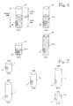
- Figure 3 illustrates one way of implementing a graphical presentation of the relative deviation or the absolute deviation.
- a column is displayed in connection with each network element (columns 31, 32 and 33 of base stations BTS1, BTS2 and BTS3).
- the height of the columns indicates the absolute deviation from the normal value.
- the colour of the column may also change with an increase in deviation so that large deviations are more easily visible on the screen. If no column exists, the performance is within the normal value. It is also possible to display alarms in connection with the deviation columns as coloured panels 36, for example. Presenting only the performance deviation informs the operator of the network elements with the lowest performance, but does not in any other way prioritize the network elements. In that case, repairs can be first directed to these network elements.
- the network element may not be able to send the alarms because of the fault, or the degraded performance is caused by malfunction of some other element and cannot be directly seen on the screen.
- Monitoring the performance according to the invention thus enables the detection of different types of hidden faults.
- Figure 4 illustrates a second way of displaying the current relative performance in relation to the normal performance.
- Columns 41, 42 and 43 in Figure 4 present the normal performance (100%) for base stations BTS1, BTS2 and BTS2.
- a coloured column 41A, 42A and 43A inside the column indicates the current performance in per cent (p%) from the normal performance. In that case, the relative deviation is 100-p%.
- Such a presentation makes it easier for the operator to perceive the level of deviation from the normal value.
- the lower the coloured column the more degraded the performance.
- the columns 41 to 43 are of equal height, and it is therefore impossible to prioritize the network elements on the basis thereof.
- Figure 5 illustrates one way of presenting the relative deviation when two PM indicators, namely the amount of traffic (for example calls in a time unit) and a dropped call ratio, are simultaneously in use.
- Columns 51 and 52 show normal performance values: height represents 100% traffic and diameter represents 100% dropped call ratio.
- the base station BTS1 has a normal situation, and only the column 51 is therefore presented on the graphical user interface.
- the base station BTS2 has a fault situation which has also caused fault alarms shown in coloured panels on the performance column. Traffic has reduced p% because of the fault. the reduction being indicated by a coloured extension 52A of the column 52, both having the same diameter.
- the height of the extension 52A is directly proportional to the reduction of traffic.
- the dropped call ratio has also increased r%, this being indicated by an increase in diameter 52B of the column 52 and possibly by a change in colour.
- the increase in diameter is directly proportional to an increase in drop call ratio. The operator thus sees the faulty network element by a change in shape and colour and by an increase in size, which considerably facilitates the detection of the network element in need of repair from the vast amount of elements on the screen.
- the columns 51 and 52 are of equal height, whereby it is impossible to prioritize the network elements on the basis thereof.
- the current and the normal performance are presented as absolute values instead of relative values.
- the absolute values of different network elements are comparable with one another, and the relative importance of each network element as compared with one another can thus be seen on the graphical user interface.
- such a comparison of the absolute values is sensible only if the amount of traffic, or an indicator corresponding thereto, is used as the performance indicator.
- the current and the normal performance presented inform the operator of the current performance (for example traffic) as compared with the normal situation.
- Figure 6 illustrates one way of presenting the normal performance, the current performance and the deviation as absolute values.
- the heights of columns 61, 62, 63 and 64 represent their absolute performance, normal traffic, for example. Therefore, the height of the column directly indicates the importance of the network element for traffic in proportion to others.
- the order of importance for the traffic is BTS1, BTS4, BTS2 and BTS3. Coloured columns 61A, 62A, 63A and 64A inside the columns 61 to 64 indicate the current performance (traffic). Consequently, it is also possible to see the effect of the fault on the performance of the network element.
- the order of repair would be BTS1, BTS2, BTS3 and BTS4 on the basis of the loss of the absolute performance.
- the order would be entirely different on the basis of the loss of the relative performance: BTS3, BTS1, BTS2 and BTS4. On the other hand, the order would be BTS2. BTS3, BTS1 and BTS4 on the basis of the number of alarms. The operator can thus receive a great amount of information at one glance, on the basis of which the operator is able to conclude the order of repair.
- the order of repair in Figure 6 would most likely be BTS1, BTS3, BTS2 and BTS4.
- Figure 7 illustrates a way of presenting only the absolute value of the normal performance.
- the height of columns 71, 72, 73 74 and 75 in Figure 7 shows their amount of traffic and, consequently, their order of importance.
- the alarms are shown as coloured panels 76, for example.
- this embodiment does not take into account the actual loss of performance.
- the normal performance or traffic and the current performance or traffic are calculated and when the average profit of the traffic, i.e. the financial value (in a performance unit and/or in a time unit, for example) is known, the economical loss (for example in a time unit) generated by the network element is calculated and presented to the operator if the fault is not observed.
- the loss can be presented as a numerical value or a graphical presentation as an absolute value, as a relative value, and so on.
- Figure 7 shows the fault-induced loss in hours (for example FIM/hour) on top of the columns. On this ground the network element generating the heaviest losses can be selected to be repaired.
- a similar way of presenting the loss can be applied to other graphical presentations representing the performance or solely to alarms without other performance information included.
Applications Claiming Priority (3)
| Application Number | Priority Date | Filing Date | Title |
|---|---|---|---|
| FI973956 | 1997-10-14 | ||
| FI973956A FI107312B (fi) | 1997-10-14 | 1997-10-14 | Verkonvalvontamenetelmä tietoliikenneverkkoa varten |
| PCT/FI1998/000794 WO1999020034A2 (fi) | 1997-10-14 | 1998-10-13 | Network monitoring method for telecommunications network |
Publications (2)
| Publication Number | Publication Date |
|---|---|
| EP1031208A2 EP1031208A2 (en) | 2000-08-30 |
| EP1031208B1 true EP1031208B1 (en) | 2005-09-21 |
Family
ID=8549727
Family Applications (1)
| Application Number | Title | Priority Date | Filing Date |
|---|---|---|---|
| EP98947583A Expired - Lifetime EP1031208B1 (en) | 1997-10-14 | 1998-10-13 | Network monitoring method for telecommunications network |
Country Status (11)
| Country | Link |
|---|---|
| US (2) | US7142820B1 (fi) |
| EP (1) | EP1031208B1 (fi) |
| JP (1) | JP2001520488A (fi) |
| CN (1) | CN1223149C (fi) |
| AT (1) | ATE305191T1 (fi) |
| AU (1) | AU9444398A (fi) |
| CA (1) | CA2305154A1 (fi) |
| DE (1) | DE69831687T2 (fi) |
| ES (1) | ES2247720T3 (fi) |
| FI (1) | FI107312B (fi) |
| WO (1) | WO1999020034A2 (fi) |
Cited By (4)
| Publication number | Priority date | Publication date | Assignee | Title |
|---|---|---|---|---|
| CN101277218B (zh) * | 2008-05-04 | 2010-12-29 | 中兴通讯股份有限公司 | 一种网络告警的动态分析系统和方法 |
| WO2011054861A1 (en) | 2009-11-03 | 2011-05-12 | Telefonica, S.A. | Monitoring and management of heterogeneous network events |
| CN102457397A (zh) * | 2010-11-01 | 2012-05-16 | 中兴通讯股份有限公司 | 一种光纤告警显示方法及系统 |
| US11057266B2 (en) | 2014-03-24 | 2021-07-06 | Microsoft Technology Licensing, Llc | Identifying troubleshooting options for resolving network failures |
Families Citing this family (45)
| Publication number | Priority date | Publication date | Assignee | Title |
|---|---|---|---|---|
| US6369820B1 (en) * | 1998-06-02 | 2002-04-09 | International Business Machines Corporation | Method and system for graphically displaying trend and range data for a variety of systems |
| US7693042B1 (en) * | 1999-06-23 | 2010-04-06 | At&T Mobility Ii Llc | Intelligent presentation network management system |
| US7447509B2 (en) * | 1999-12-22 | 2008-11-04 | Celeritasworks, Llc | Geographic management system |
| US8452776B2 (en) | 1999-12-22 | 2013-05-28 | Celeritasworks, Llc | Spatial data portal |
| US6343290B1 (en) * | 1999-12-22 | 2002-01-29 | Celeritas Technologies, L.L.C. | Geographic network management system |
| CA2365430A1 (en) | 2001-12-19 | 2003-06-19 | Alcatel Canada Inc. | System and method for collecting statistics for a communication network |
| EP1561350B1 (en) * | 2002-11-06 | 2008-07-16 | Telefonaktiebolaget LM Ericsson (publ) | A means and a method relating to optimization of network operation and planning |
| US7962589B1 (en) | 2002-11-07 | 2011-06-14 | Cisco Technology, Inc. | Method and apparatus for providing notification of network alarms using a plurality of distributed layers |
| CA2475335A1 (en) * | 2003-07-22 | 2005-01-22 | At&T Corp. | Method for three-dimensional inventory link |
| GB0324597D0 (en) * | 2003-10-21 | 2003-11-26 | Nokia Corp | A communication system |
| US7084752B2 (en) * | 2004-05-12 | 2006-08-01 | Cisco Technology, Inc. | Method and apparatus for triage of network alarms |
| US7596716B2 (en) * | 2004-07-29 | 2009-09-29 | Sobha Renaissance Information Technology | Method and system for managing networks |
| FI20050017A0 (fi) | 2005-01-07 | 2005-01-07 | Nokia Corp | Binääriluokkaan perustuva analysointi ja monitorointi |
| FI20050625A0 (fi) * | 2005-06-13 | 2005-06-13 | Nokia Corp | Binääriluokkaan perustuva valvonta |
| US20070053317A1 (en) * | 2005-09-08 | 2007-03-08 | Bellsouth Intellectual Property Corporation | Methods and systems for monitoring a wireless broadband base station |
| GB2433678B (en) * | 2005-12-14 | 2007-12-05 | Motorola Inc | Alarm condition detection in a cellular communication system |
| CN1983972A (zh) * | 2006-05-08 | 2007-06-20 | 华为技术有限公司 | 一种路径性能的显示、调节、分析方法及装置 |
| CN1921410B (zh) * | 2006-09-06 | 2010-05-12 | 华为技术有限公司 | 显示网元位置的装置、方法及监控网络状态的方法 |
| US8078972B2 (en) * | 2006-09-15 | 2011-12-13 | Citrix Systems, Inc. | Methods and interfaces for displaying performance data related to a current remote access session |
| US7978617B2 (en) | 2006-09-15 | 2011-07-12 | Citrix Systems, Inc. | Methods for providing performance improvement recommendations |
| US20080080435A1 (en) * | 2006-09-29 | 2008-04-03 | Symbol Technologies, Inc. | Methods and apparatus for abstracting the state of an RF network |
| US8484336B2 (en) | 2006-11-15 | 2013-07-09 | Cisco Technology, Inc. | Root cause analysis in a communication network |
| CN101192962B (zh) * | 2006-11-24 | 2011-04-20 | 中兴通讯股份有限公司 | 电信网管系统中涉及粘滞值的告警产生和恢复方法 |
| US8238258B2 (en) * | 2006-12-08 | 2012-08-07 | At&T Intellectual Property I, L.P. | System and method of managing network performance |
| US7640460B2 (en) * | 2007-02-28 | 2009-12-29 | Microsoft Corporation | Detect user-perceived faults using packet traces in enterprise networks |
| US8015139B2 (en) * | 2007-03-06 | 2011-09-06 | Microsoft Corporation | Inferring candidates that are potentially responsible for user-perceptible network problems |
| US8443074B2 (en) | 2007-03-06 | 2013-05-14 | Microsoft Corporation | Constructing an inference graph for a network |
| CN101068273B (zh) * | 2007-06-05 | 2010-05-26 | 中国移动通信集团公司 | 电信网管预警系统及方法 |
| US8145186B1 (en) * | 2008-03-31 | 2012-03-27 | Sprint Communications Company L.P. | Assessing the comparative performance of telecommunication service areas |
| US9119092B1 (en) * | 2008-05-06 | 2015-08-25 | Sprint Spectrum L.P. | Performance based selection of channel elements for use in a wireless network |
| US20100097956A1 (en) * | 2008-10-20 | 2010-04-22 | Toshiba America Research, Inc. | Multi-interface management configuration method and graphical user interface for connection manager |
| JP2010102461A (ja) * | 2008-10-23 | 2010-05-06 | Kddi Corp | 故障リスク評価装置 |
| US7954010B2 (en) * | 2008-12-12 | 2011-05-31 | At&T Intellectual Property I, L.P. | Methods and apparatus to detect an error condition in a communication network |
| US8442515B2 (en) * | 2009-11-19 | 2013-05-14 | Kentrox, Inc. | Management system for monitoring and controlling remote sites and equipment |
| US20110122761A1 (en) * | 2009-11-23 | 2011-05-26 | Sundar Sriram | KPI Driven High Availability Method and apparatus for UMTS radio access networks |
| US8819206B2 (en) * | 2010-10-05 | 2014-08-26 | Infinera Corporation | Graph based flexible service discovery and management system and method |
| CN102932170B (zh) * | 2012-10-22 | 2016-06-22 | 中兴通讯股份有限公司 | 网元负载不均检测处理方法、装置及其系统 |
| US11528195B2 (en) * | 2013-03-15 | 2022-12-13 | NetBrain Technologies, Inc. | System for creating network troubleshooting procedure |
| CN104918276A (zh) * | 2014-03-10 | 2015-09-16 | 中国移动通信集团上海有限公司 | 一种故障网元设备的确定方法、装置及设备 |
| WO2015182831A1 (ko) * | 2014-05-30 | 2015-12-03 | 삼성에스디에스 주식회사 | 시스템 모니터링 장치 및 방법 |
| CN104125102B (zh) * | 2014-08-12 | 2017-10-03 | 浪潮天元通信信息系统有限公司 | 一种实时监控网络设备运行数据完整性的方法 |
| CN107078792B (zh) * | 2015-05-07 | 2020-05-08 | 电信发展中心 | 光纤故障定位系统 |
| US11736365B2 (en) | 2015-06-02 | 2023-08-22 | NetBrain Technologies, Inc. | System and method for network management automation |
| US20170034720A1 (en) * | 2015-07-28 | 2017-02-02 | Futurewei Technologies, Inc. | Predicting Network Performance |
| CN113810239A (zh) * | 2020-06-15 | 2021-12-17 | 深信服科技股份有限公司 | 数据中心网络故障检测方法、装置、设备及存储介质 |
Family Cites Families (13)
| Publication number | Priority date | Publication date | Assignee | Title |
|---|---|---|---|---|
| DE4118356C2 (de) * | 1991-06-05 | 1994-08-11 | Ant Nachrichtentech | Verfahren zum Steuern und Überwachen eines Nachrichtenübertragungsnetzes |
| JP3094593B2 (ja) | 1991-12-10 | 2000-10-03 | 株式会社日立製作所 | 情報ネットワーク監視システム |
| US5572189A (en) * | 1992-03-02 | 1996-11-05 | Fujitsu Ltd. | Alarm collection apparatus of central maintenance operation center |
| GB9222282D0 (en) * | 1992-10-22 | 1992-12-09 | Hewlett Packard Co | Monitoring network status |
| US5490285A (en) | 1993-05-20 | 1996-02-06 | Motorola, Inc. | Method of topographically displaying selected information in a cellular communication system |
| US5596703A (en) | 1993-10-22 | 1997-01-21 | Lucent Technologies Inc. | Graphical display of relationships |
| US5566092A (en) * | 1993-12-30 | 1996-10-15 | Caterpillar Inc. | Machine fault diagnostics system and method |
| WO1996020549A1 (en) * | 1994-12-23 | 1996-07-04 | British Telecommunications Public Limited Company | Fault monitoring |
| JPH09223092A (ja) | 1996-02-14 | 1997-08-26 | Nippon Telegr & Teleph Corp <Ntt> | ネットワーク管理方法及びシステム |
| US6118936A (en) * | 1996-04-18 | 2000-09-12 | Mci Communications Corporation | Signaling network management system for converting network events into standard form and then correlating the standard form events with topology and maintenance information |
| EP0849911A3 (en) | 1996-12-18 | 1999-02-10 | Nortel Networks Corporation | Communications network monitoring |
| US6445774B1 (en) * | 1997-11-17 | 2002-09-03 | Mci Communications Corporation | System for automated workflow in a network management and operations system |
| US6067030A (en) * | 1998-03-13 | 2000-05-23 | At&T Corp. | Method and apparatus for providing network infrastructure information for a network control center |
-
1997
- 1997-10-14 FI FI973956A patent/FI107312B/fi active
-
1998
- 1998-10-13 JP JP2000516476A patent/JP2001520488A/ja active Pending
- 1998-10-13 US US09/529,178 patent/US7142820B1/en not_active Expired - Lifetime
- 1998-10-13 AT AT98947583T patent/ATE305191T1/de not_active IP Right Cessation
- 1998-10-13 WO PCT/FI1998/000794 patent/WO1999020034A2/fi active IP Right Grant
- 1998-10-13 DE DE69831687T patent/DE69831687T2/de not_active Expired - Lifetime
- 1998-10-13 CN CN98810180.7A patent/CN1223149C/zh not_active Expired - Lifetime
- 1998-10-13 AU AU94443/98A patent/AU9444398A/en not_active Abandoned
- 1998-10-13 ES ES98947583T patent/ES2247720T3/es not_active Expired - Lifetime
- 1998-10-13 EP EP98947583A patent/EP1031208B1/en not_active Expired - Lifetime
- 1998-10-13 CA CA002305154A patent/CA2305154A1/en not_active Abandoned
-
2006
- 2006-07-18 US US11/487,995 patent/US7430401B2/en not_active Expired - Fee Related
Cited By (4)
| Publication number | Priority date | Publication date | Assignee | Title |
|---|---|---|---|---|
| CN101277218B (zh) * | 2008-05-04 | 2010-12-29 | 中兴通讯股份有限公司 | 一种网络告警的动态分析系统和方法 |
| WO2011054861A1 (en) | 2009-11-03 | 2011-05-12 | Telefonica, S.A. | Monitoring and management of heterogeneous network events |
| CN102457397A (zh) * | 2010-11-01 | 2012-05-16 | 中兴通讯股份有限公司 | 一种光纤告警显示方法及系统 |
| US11057266B2 (en) | 2014-03-24 | 2021-07-06 | Microsoft Technology Licensing, Llc | Identifying troubleshooting options for resolving network failures |
Also Published As
| Publication number | Publication date |
|---|---|
| CN1276118A (zh) | 2000-12-06 |
| FI973956A0 (fi) | 1997-10-14 |
| WO1999020034A3 (fi) | 1999-07-01 |
| AU9444398A (en) | 1999-05-03 |
| JP2001520488A (ja) | 2001-10-30 |
| ATE305191T1 (de) | 2005-10-15 |
| FI107312B (fi) | 2001-06-29 |
| WO1999020034A9 (fi) | 2000-06-15 |
| DE69831687T2 (de) | 2006-07-06 |
| CN1223149C (zh) | 2005-10-12 |
| DE69831687D1 (de) | 2006-02-02 |
| US7430401B2 (en) | 2008-09-30 |
| US20060258348A1 (en) | 2006-11-16 |
| FI973956A (fi) | 1999-04-15 |
| EP1031208A2 (en) | 2000-08-30 |
| ES2247720T3 (es) | 2006-03-01 |
| US7142820B1 (en) | 2006-11-28 |
| CA2305154A1 (en) | 1999-04-22 |
| WO1999020034A2 (fi) | 1999-04-22 |
Similar Documents
| Publication | Publication Date | Title |
|---|---|---|
| EP1031208B1 (en) | Network monitoring method for telecommunications network | |
| US5621664A (en) | Monitoring system status | |
| AU671194B2 (en) | Event correlation | |
| US6259972B1 (en) | Method for processing and disseminating utility outage information | |
| US6115743A (en) | Interface system for integrated monitoring and management of network devices in a telecommunication network | |
| EP1834444B1 (en) | Binary class based analysis and monitoring | |
| CN102165811B (zh) | 具有节制点的无线网状网络和用于识别无线网状网络内的节制点的方法 | |
| EP1326376A2 (en) | Geographical network management system | |
| CN105049223B (zh) | 一种电力通信网缺陷故障处理决策辅助分析方法 | |
| CN103150598B (zh) | 输电网突发故障处理系统和方法 | |
| EP0598484B1 (en) | Monitoring system status | |
| CN103914057B (zh) | 一种工控设备自动化系统的故障诊断和分析方法及系统 | |
| CN108767989A (zh) | 一种配电自动化系统的工作状态监控系统及分析方法 | |
| CN103812694A (zh) | 基于ArcGIS网格化的投诉热点监控与分析系统及其方法 | |
| CN109451273A (zh) | 一种应急指挥调度系统和方法 | |
| WO2017171677A1 (en) | The method and system of monitoring the lv (low voltage) electricity infrastructure using gsm communication technology and taking precautionary measures | |
| CN108550097B (zh) | 一种远程智慧消防管理系统 | |
| EP2888860B1 (en) | Communication configuration analysis in process control systems | |
| CN111509863B (zh) | 一种移动变电站监控报警系统及方法 | |
| KR100521738B1 (ko) | 지식 기반 망 관리 시스템에서 지식데이터 최적화 방법 | |
| Kamarulzaman et al. | Substation alarm monitoring system | |
| CN110932897A (zh) | 一种跨网环境下的分级统一运维管理平台 | |
| Osahenvemwen et al. | Analysis On GSM Fault Management Unit. |
Legal Events
| Date | Code | Title | Description |
|---|---|---|---|
| PUAI | Public reference made under article 153(3) epc to a published international application that has entered the european phase |
Free format text: ORIGINAL CODE: 0009012 |
|
| 17P | Request for examination filed |
Effective date: 20000407 |
|
| AK | Designated contracting states |
Kind code of ref document: A2 Designated state(s): AT BE CH CY DE DK ES FI FR GB GR IE IT LI LU MC NL PT SE |
|
| RAP1 | Party data changed (applicant data changed or rights of an application transferred) |
Owner name: NOKIA CORPORATION |
|
| 17Q | First examination report despatched |
Effective date: 20040511 |
|
| GRAP | Despatch of communication of intention to grant a patent |
Free format text: ORIGINAL CODE: EPIDOSNIGR1 |
|
| GRAS | Grant fee paid |
Free format text: ORIGINAL CODE: EPIDOSNIGR3 |
|
| GRAA | (expected) grant |
Free format text: ORIGINAL CODE: 0009210 |
|
| AK | Designated contracting states |
Kind code of ref document: B1 Designated state(s): AT BE CH CY DE DK ES FI FR GB GR IE IT LI LU MC NL PT SE |
|
| PG25 | Lapsed in a contracting state [announced via postgrant information from national office to epo] |
Ref country code: NL Free format text: LAPSE BECAUSE OF FAILURE TO SUBMIT A TRANSLATION OF THE DESCRIPTION OR TO PAY THE FEE WITHIN THE PRESCRIBED TIME-LIMIT Effective date: 20050921 Ref country code: LI Free format text: LAPSE BECAUSE OF FAILURE TO SUBMIT A TRANSLATION OF THE DESCRIPTION OR TO PAY THE FEE WITHIN THE PRESCRIBED TIME-LIMIT Effective date: 20050921 Ref country code: FI Free format text: LAPSE BECAUSE OF FAILURE TO SUBMIT A TRANSLATION OF THE DESCRIPTION OR TO PAY THE FEE WITHIN THE PRESCRIBED TIME-LIMIT Effective date: 20050921 Ref country code: CH Free format text: LAPSE BECAUSE OF FAILURE TO SUBMIT A TRANSLATION OF THE DESCRIPTION OR TO PAY THE FEE WITHIN THE PRESCRIBED TIME-LIMIT Effective date: 20050921 Ref country code: BE Free format text: LAPSE BECAUSE OF FAILURE TO SUBMIT A TRANSLATION OF THE DESCRIPTION OR TO PAY THE FEE WITHIN THE PRESCRIBED TIME-LIMIT Effective date: 20050921 Ref country code: AT Free format text: LAPSE BECAUSE OF FAILURE TO SUBMIT A TRANSLATION OF THE DESCRIPTION OR TO PAY THE FEE WITHIN THE PRESCRIBED TIME-LIMIT Effective date: 20050921 |
|
| REG | Reference to a national code |
Ref country code: GB Ref legal event code: FG4D |
|
| REG | Reference to a national code |
Ref country code: CH Ref legal event code: EP |
|
| PG25 | Lapsed in a contracting state [announced via postgrant information from national office to epo] |
Ref country code: IE Free format text: LAPSE BECAUSE OF NON-PAYMENT OF DUE FEES Effective date: 20051013 Ref country code: CY Free format text: LAPSE BECAUSE OF FAILURE TO SUBMIT A TRANSLATION OF THE DESCRIPTION OR TO PAY THE FEE WITHIN THE PRESCRIBED TIME-LIMIT Effective date: 20051013 |
|
| REG | Reference to a national code |
Ref country code: IE Ref legal event code: FG4D |
|
| REF | Corresponds to: |
Ref document number: 69831687 Country of ref document: DE Date of ref document: 20051027 Kind code of ref document: P |
|
| PG25 | Lapsed in a contracting state [announced via postgrant information from national office to epo] |
Ref country code: MC Free format text: LAPSE BECAUSE OF NON-PAYMENT OF DUE FEES Effective date: 20051031 |
|
| PG25 | Lapsed in a contracting state [announced via postgrant information from national office to epo] |
Ref country code: LU Free format text: LAPSE BECAUSE OF NON-PAYMENT OF DUE FEES Effective date: 20051121 |
|
| PG25 | Lapsed in a contracting state [announced via postgrant information from national office to epo] |
Ref country code: SE Free format text: LAPSE BECAUSE OF FAILURE TO SUBMIT A TRANSLATION OF THE DESCRIPTION OR TO PAY THE FEE WITHIN THE PRESCRIBED TIME-LIMIT Effective date: 20051221 Ref country code: GR Free format text: LAPSE BECAUSE OF FAILURE TO SUBMIT A TRANSLATION OF THE DESCRIPTION OR TO PAY THE FEE WITHIN THE PRESCRIBED TIME-LIMIT Effective date: 20051221 Ref country code: DK Free format text: LAPSE BECAUSE OF FAILURE TO SUBMIT A TRANSLATION OF THE DESCRIPTION OR TO PAY THE FEE WITHIN THE PRESCRIBED TIME-LIMIT Effective date: 20051221 |
|
| REF | Corresponds to: |
Ref document number: 69831687 Country of ref document: DE Date of ref document: 20060202 Kind code of ref document: P |
|
| PG25 | Lapsed in a contracting state [announced via postgrant information from national office to epo] |
Ref country code: PT Free format text: LAPSE BECAUSE OF FAILURE TO SUBMIT A TRANSLATION OF THE DESCRIPTION OR TO PAY THE FEE WITHIN THE PRESCRIBED TIME-LIMIT Effective date: 20060221 |
|
| NLV1 | Nl: lapsed or annulled due to failure to fulfill the requirements of art. 29p and 29m of the patents act | ||
| REG | Reference to a national code |
Ref country code: ES Ref legal event code: FG2A Ref document number: 2247720 Country of ref document: ES Kind code of ref document: T3 |
|
| REG | Reference to a national code |
Ref country code: CH Ref legal event code: PL |
|
| ET | Fr: translation filed | ||
| PLBE | No opposition filed within time limit |
Free format text: ORIGINAL CODE: 0009261 |
|
| STAA | Information on the status of an ep patent application or granted ep patent |
Free format text: STATUS: NO OPPOSITION FILED WITHIN TIME LIMIT |
|
| REG | Reference to a national code |
Ref country code: IE Ref legal event code: MM4A |
|
| 26N | No opposition filed |
Effective date: 20060622 |
|
| PGFP | Annual fee paid to national office [announced via postgrant information from national office to epo] |
Ref country code: ES Payment date: 20140911 Year of fee payment: 17 |
|
| PGFP | Annual fee paid to national office [announced via postgrant information from national office to epo] |
Ref country code: FR Payment date: 20141008 Year of fee payment: 17 |
|
| PGFP | Annual fee paid to national office [announced via postgrant information from national office to epo] |
Ref country code: IT Payment date: 20141013 Year of fee payment: 17 |
|
| REG | Reference to a national code |
Ref country code: GB Ref legal event code: 732E Free format text: REGISTERED BETWEEN 20150910 AND 20150916 |
|
| REG | Reference to a national code |
Ref country code: DE Ref legal event code: R082 Ref document number: 69831687 Country of ref document: DE Representative=s name: BECKER, KURIG, STRAUS, DE Ref country code: DE Ref legal event code: R081 Ref document number: 69831687 Country of ref document: DE Owner name: NOKIA TECHNOLOGIES OY, FI Free format text: FORMER OWNER: NOKIA CORP., 02610 ESPOO, FI |
|
| REG | Reference to a national code |
Ref country code: ES Ref legal event code: PC2A Owner name: NOKIA TECHNOLOGIES OY Effective date: 20151124 |
|
| PG25 | Lapsed in a contracting state [announced via postgrant information from national office to epo] |
Ref country code: IT Free format text: LAPSE BECAUSE OF NON-PAYMENT OF DUE FEES Effective date: 20151013 |
|
| REG | Reference to a national code |
Ref country code: FR Ref legal event code: ST Effective date: 20160630 |
|
| PG25 | Lapsed in a contracting state [announced via postgrant information from national office to epo] |
Ref country code: FR Free format text: LAPSE BECAUSE OF NON-PAYMENT OF DUE FEES Effective date: 20151102 |
|
| REG | Reference to a national code |
Ref country code: ES Ref legal event code: FD2A Effective date: 20161125 |
|
| PG25 | Lapsed in a contracting state [announced via postgrant information from national office to epo] |
Ref country code: ES Free format text: LAPSE BECAUSE OF NON-PAYMENT OF DUE FEES Effective date: 20151014 |
|
| PGFP | Annual fee paid to national office [announced via postgrant information from national office to epo] |
Ref country code: DE Payment date: 20171011 Year of fee payment: 20 |
|
| PGFP | Annual fee paid to national office [announced via postgrant information from national office to epo] |
Ref country code: GB Payment date: 20171011 Year of fee payment: 20 |
|
| REG | Reference to a national code |
Ref country code: DE Ref legal event code: R071 Ref document number: 69831687 Country of ref document: DE |
|
| REG | Reference to a national code |
Ref country code: GB Ref legal event code: PE20 Expiry date: 20181012 |
|
| PG25 | Lapsed in a contracting state [announced via postgrant information from national office to epo] |
Ref country code: GB Free format text: LAPSE BECAUSE OF EXPIRATION OF PROTECTION Effective date: 20181012 |