EP1030984B1 - Verfahren zum steuern eines automatgetriebes - Google Patents
Verfahren zum steuern eines automatgetriebes Download PDFInfo
- Publication number
- EP1030984B1 EP1030984B1 EP98959862A EP98959862A EP1030984B1 EP 1030984 B1 EP1030984 B1 EP 1030984B1 EP 98959862 A EP98959862 A EP 98959862A EP 98959862 A EP98959862 A EP 98959862A EP 1030984 B1 EP1030984 B1 EP 1030984B1
- Authority
- EP
- European Patent Office
- Prior art keywords
- input speed
- transmission input
- grad
- clutch
- point
- Prior art date
- Legal status (The legal status is an assumption and is not a legal conclusion. Google has not performed a legal analysis and makes no representation as to the accuracy of the status listed.)
- Expired - Lifetime
Links
- 238000000034 method Methods 0.000 title claims description 20
- 230000008569 process Effects 0.000 title description 5
- 230000005540 biological transmission Effects 0.000 claims description 108
- 230000000694 effects Effects 0.000 claims description 26
- 230000002265 prevention Effects 0.000 claims description 5
- 238000010586 diagram Methods 0.000 description 12
- 230000006870 function Effects 0.000 description 12
- 239000000243 solution Substances 0.000 description 12
- 238000002485 combustion reaction Methods 0.000 description 10
- 230000007704 transition Effects 0.000 description 9
- 230000008859 change Effects 0.000 description 6
- 230000006399 behavior Effects 0.000 description 4
- 230000008901 benefit Effects 0.000 description 3
- 230000008878 coupling Effects 0.000 description 3
- 238000010168 coupling process Methods 0.000 description 3
- 238000005859 coupling reaction Methods 0.000 description 3
- 230000001105 regulatory effect Effects 0.000 description 3
- 229910052757 nitrogen Inorganic materials 0.000 description 2
- 229910052698 phosphorus Inorganic materials 0.000 description 2
- 230000001360 synchronised effect Effects 0.000 description 2
- 230000001276 controlling effect Effects 0.000 description 1
- 230000036461 convulsion Effects 0.000 description 1
- 230000001419 dependent effect Effects 0.000 description 1
- 239000007787 solid Substances 0.000 description 1
Images


Classifications
-
- F—MECHANICAL ENGINEERING; LIGHTING; HEATING; WEAPONS; BLASTING
- F16—ENGINEERING ELEMENTS AND UNITS; GENERAL MEASURES FOR PRODUCING AND MAINTAINING EFFECTIVE FUNCTIONING OF MACHINES OR INSTALLATIONS; THERMAL INSULATION IN GENERAL
- F16H—GEARING
- F16H61/00—Control functions within control units of change-speed- or reversing-gearings for conveying rotary motion ; Control of exclusively fluid gearing, friction gearing, gearings with endless flexible members or other particular types of gearing
- F16H61/02—Control functions within control units of change-speed- or reversing-gearings for conveying rotary motion ; Control of exclusively fluid gearing, friction gearing, gearings with endless flexible members or other particular types of gearing characterised by the signals used
- F16H61/0202—Control functions within control units of change-speed- or reversing-gearings for conveying rotary motion ; Control of exclusively fluid gearing, friction gearing, gearings with endless flexible members or other particular types of gearing characterised by the signals used the signals being electric
- F16H61/0204—Control functions within control units of change-speed- or reversing-gearings for conveying rotary motion ; Control of exclusively fluid gearing, friction gearing, gearings with endless flexible members or other particular types of gearing characterised by the signals used the signals being electric for gearshift control, e.g. control functions for performing shifting or generation of shift signal
-
- F—MECHANICAL ENGINEERING; LIGHTING; HEATING; WEAPONS; BLASTING
- F16—ENGINEERING ELEMENTS AND UNITS; GENERAL MEASURES FOR PRODUCING AND MAINTAINING EFFECTIVE FUNCTIONING OF MACHINES OR INSTALLATIONS; THERMAL INSULATION IN GENERAL
- F16H—GEARING
- F16H61/00—Control functions within control units of change-speed- or reversing-gearings for conveying rotary motion ; Control of exclusively fluid gearing, friction gearing, gearings with endless flexible members or other particular types of gearing
- F16H61/04—Smoothing ratio shift
- F16H61/06—Smoothing ratio shift by controlling rate of change of fluid pressure
- F16H61/061—Smoothing ratio shift by controlling rate of change of fluid pressure using electric control means
Definitions
- the invention relates to a method for controlling a Automatic transmission, in which an electronic transmission control during a shift transition from a transmission input speed the actual gradient determined and over a Target / actual comparison with a default value the deviation determined from this.
- the clutches involved in the switching transition are then regulated so that the deviation Actual to target gradient of the transmission input speed is reduced becomes.
- the shifting time determines comfort a switching transition.
- Switching time is understood the period during which a transmission input speed from a speed level of a first gear ratio to a speed level of a second speed ratio changed. Switching time too short causes a clear shift jerk, a too long switching time causes excessive heat input into the switch transition involved clutches. In this respect, the Switching time a compromise between the two previously mentioned Extremes.
- a method of control / regulation a switching transition strikes z. B. EP-PS 0 339 664 in front. With this method, a switching time is set by an actual gradient from the transmission input speed calculated and this tracked a target gradient becomes.
- EP 0 790 441 A2 discloses an electronic transmission control an automatic transmission, which, in order to To control the clutch of the automatic transmission, an actual gradient the speed determines this actual gradient with compares a target gradient and as a function of this difference regulates the oil pressure on the clutch.
- the invention lies in that Task based, the behavior of the automatic transmission tighter to couple to the behavior of the driver.
- a first solution according to the invention is that an electronic transmission control in a first operating mode from input variables of the vehicle and the driver cyclically calculates a driving activity and the target gradient the transmission input speed depending on the Driving activity changed. Dial in a second mode the electronic transmission control a special program several and changes the target gradient of the transmission input speed depending on the selected special program. As stated in claim 2, this is in the first operating mode the target gradient changed in the sense that with a higher driving activity a larger one Target gradient is set.
- the solution according to the invention and its design has the advantage that a driver is responsible for his behavior Switching sequences determined. With a comfort-oriented driving style this results in soft, long circuits. Out A sporty driving style results in short circuits. In automatic transmissions with a so-called "intelligent" Shift program becomes a driving activity for the selection of the shift points calculated. Such a method is e.g. B. from DE-PS 39 22 051 and DE-OS 39 41 999 known. For the Solution according to the invention thus results as a further advantage that the driving activity already determined is used and thus the solution according to the invention in one existing software can be integrated inexpensively.
- the target gradient Gearbox input speed changed in the direction of small values becomes active when one of the following special programs is: winter program or slip control of the drive wheels or cruise control function or city program.
- winter program or slip control of the drive wheels or cruise control function or city program Through this configuration causes the switching transitions to be very smooth are executed and z. B. in the winter program safety-critical Driving situations can be prevented.
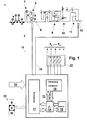
- FIG. 1 shows a system diagram of an automatic transmission.
- This consists of the actual mechanical part, a hydrodynamic converter 3, a hydraulic control unit 21 and an electronic transmission control 13.
- the automatic transmission is driven by a drive unit 1, preferably internal combustion engine, via a drive shaft 2.
- a drive unit 1 preferably internal combustion engine
- the hydrodynamic converter 3 consists of a pump wheel 4, a turbine wheel 5 and a stator 6.
- Parallel to the hydrodynamic converter 3 is a converter clutch 7 arranged.
- the converter clutch 7 and the turbine wheel 5 lead to a turbine shaft 8. With the converter clutch actuated 7, the turbine shaft 8 has the same speed as the drive shaft 2.
- the mechanical part of the automatic transmission consists of clutches and brakes A to G, one Freewheel 10 (FL1), a Ravigneaux set 9 and a subordinate Planetary gear set 11.
- the output takes place via a transmission output shaft 12. This does not lead to a shown differential, which over two axle half-waves the drive wheels of a vehicle, not shown drive. Via a corresponding clutch / brake combination a gear step is determined.
- the assignment of the Clutch logic for the gear stage can be seen in FIG. 2. So z. B. in a downshift from the fourth in third gear the brake C is closed and the clutch E deactivated.
- the circuits are from the second to the fifth translation stage each as overlap circuits executed. Since the mechanical part for the further Understanding of the invention is not relevant to one detailed description omitted.
- the electronic transmission control 13 selects an appropriate drive level depending on the input variables 18 to 20.
- the electronic transmission control 13 then activates a corresponding clutch / brake combination via the hydraulic control unit 21, in which there are electromagnetic actuators.
- the electronic transmission control 13 determines the pressure curve of the clutches / brakes involved in the shift.
- the electronic transmission control 13 is represented in a highly simplified form as blocks: Micro-controller 14, memory 15, function block control actuators 16 and function block calculation 17.
- the transmission-relevant data are stored in memory 15. Transmission-relevant data are e.g. B. programs, shift maps and vehicle-specific parameters as well as diagnostic data.
- the memory 15 is usually designed as an EPROM, EEPROM or as a buffered RAM.
- the function block control actuators 16 is used to control the actuators located in the hydraulic control unit 21.
- Input variables 20 are supplied to electronic transmission control 13.
- Input variables 20 are e.g. For example, a variable representing the driver's desired performance, such as the accelerator pedal / throttle valve position, or manual shift requests, the signal of the torque output by the internal combustion engine, the speed or temperature of the internal combustion engine, etc.
- the internal combustion engine-specific data is provided by an engine control unit provides. This is not shown in Fig. 1.
- the electronic transmission control 13 receives the speed of the turbine shaft 18 and the transmission output shaft 19 as further input variables.
- reference number 22 in FIG. 1 shows a program selector switch so that the method can also be used for conventional automatic transmissions.
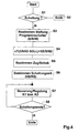
- step S1 shows a program flow chart for the first solution according to the invention.
- This is preferably used in automatic transmissions with an intelligent shift program.
- An intelligent circuit program is such.
- B. from DE-PS 39 22 051 and DE-OS 39 41 999 known.
- a driving activity FA is determined from vehicle-specific variables and the behavior of the driver.
- the driving activity FA ultimately determines the shift point of the automatic transmission.
- the range of values within which the gradient setpoint can be adjusted is defined by a maximum and minimum gradient value.
- step S7 the gradient setpoint nt (GRAD-TARGET) of the transmission input speed is then defined as a function of the special program. This is realized in such a way that the target gradient is changed in the direction of smaller values when the winter program or the slip control of the drive wheels or the cruise control function or the city program is active.
- the target gradient is also set in the direction of smaller values when the special upshift prevention program has ended.
- the special upshift prevention program prevents a shift transition from being carried out. This configuration prevents the driver from ending the upshift prevention, e.g. B. after driving through a curve, surprised by a too hard circuit.
- the target gradient of the transmission input speed is changed in the direction of large values, in the sense of a shorter switching time, if the uphill / trailer program or the downhill program are activated. This ensures that, for. B. when driving uphill with a trailer after a train downshift, a sufficiently high output torque is quickly available.
- step S8 it is determined whether the shift takes place as a pull or a push shift.
- step S9 it is determined whether an upshift or a downshift is requested.
- step S10 the clutches involved in the shift are then controlled / regulated in the case of an overlap shift, a first opening clutch K1 and a second closing clutch K2. Then follows in step S11 whether the circuit end, z. B. the synchronization point was recognized. If this is not the case, a waiting loop is run through. If the end of the circuit is recognized, the program is ended.
- step S3 the program flow chart is identical to that from FIG. 3, so that what is described there applies.
- step S3 determines the position of the program selector located.
- step S4 is dependent this program selector switch the gradient setpoint nT (GRAD-TOLL) of the gearbox input speed specified. In practice, this is done so that in the program switch position "E” and "W” a very small gradient setpoint in the sense of a long switching time.
- Steps S5 to S8 are identical to steps S8 to S11 of FIG. 3, so that what has been described also applies there.
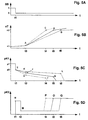
- the first case example shown in FIGS. 5B to 5D as a solid line, represents a compromise between a sporty and a comfortable shifting sequence.
- FIG. 5B this corresponds to the curve with points A and B.
- FIG. 5C the curve with points E, F and G.
- FIG. 5D the curve with points M, N and O.
- the sequence is as follows: At time t1 the electronic transmission control 13 issues the shift command SB to the automatic transmission. As a result, the pressure level of the first clutch K1 is reduced from a first pressure level p1 to a second pressure level p2. A negative pressure ramp then begins for the first clutch up to time t3 in point F.
- the second clutch K2 is acted upon by a high pressure level, the rapid filling pressure, until time t2.
- the filling compensation phase for the second clutch K2 then begins. Due to the reduced pressure level of the first clutch K1, the transmission input speed nT begins to increase at time t3. In the period t3 to t5, the pressure level of the first clutch K1 is reduced according to a second negative pressure ramp. Shortly before the time t5, the pressure level of the second clutch is increased very strongly, so that it takes over the engine load when the transmission input speed nT has reached the synchronous point at point B at the time t5. Then the pressure level of the second clutch K2 remains constant at this pressure level. After time t5, the first clutch K1 is switched off.
- the second case example shown in FIGS. 5B to 5D as a dashed line, represents a circuit sequence for a sporty driving style, in the sense of high driving activity FA.
- this corresponds to the curve with points A and C.
- FIG 5C the curve with the points E, H and J and in FIG. 5D the curve with the points M, N and P.
- the pressure level of point H of the first clutch K1 is at a lower pressure level than that of point F.
- the transmission input speed nT begins to increase more rapidly at time t3 than in the first case example.
- a negative pressure ramp follows in the period t3 / t4, end point J.
- the pressure level of the second clutch K2 is increased rapidly, pressure level point P, so that it is at the synchronization point, this corresponds to point C in FIG B that can safely take the load.
- the third case example drawn as a dash-dotted line, shows a comfortable switching sequence.
- Fig. 5B this corresponds to the curve with points A and D.
- Fig. 5C this corresponds to the curve with points E, K and L and in Fig. 5D this corresponds to the curve with points M, N and Q.
- Bis at time t3 the course is identical.
- the first clutch K1 has reached the pressure level of point K.
- the pressure level K is at a higher level than that of point F.
- the transmission input speed nT begins to increase more slowly than in the first case example.
- a negative pressure ramp acts for the first clutch K1 in the period t3 to t6 at point L.
- the pressure level of the second clutch K2 is increased, the pressure level corresponds to the point Q.
- the second clutch K2 takes over the load of the internal combustion engine at the synchronization point D. 5B, the curve A and C corresponds to the maximum possible gradient GRAD (MAX) of the transmission input speed nT. This results from the fastest possible startup of the internal combustion engine under the condition that the first clutch K1 is switched off.
- MAX maximum possible gradient GRAD
- the curve with the points A and D represents the smallest possible gradient GRAD (MIN) of the transmission input speed nT. This results from the maximum permissible heat input of the second clutch K2. Between these two curves, the gradient setpoint nT (GRAD-TARGET) of the transmission input speed nT can then be varied as a function of the driving activity FA.
- end point G When the pressure level of the point is reached F of the second clutch K2 begins for this a second Pressure ramp, end point G.
- the end point G or the point in time t6 corresponds to the synchronization point of the second Translation level. This corresponds to point B in FIG. 6B.
- the synchronization point is reached at time t6, this becomes Pressure level of the second clutch K2 gradually up to Pressure level of point H, time t7, increased. After that is the circuit ended.
- the second case example, in Figs. 6B and 6D as Dotted line represents a circuit sequence with a sporty driving style.
- the first pressure ramp the second clutch K2, start point E and end point F1 is however steeper than the first case study executed. This causes that at time t3 in Point A the transmission input speed with a larger Gradients in the direction of the synchronization point of the second Gear ratio, the synchronization point corresponds to point C. in Fig. 6B.
- the pressure level F1 is reached the second clutch K2 begins for this until the time t4, end point J, a second pressure ramp.
- Point of time t4 corresponds to the point in time when the transmission input speed nT reaches the synchronization point C. After that the pressure level of the clutch K2 ramps up to the pressure level of point K, time t5, increased. Here the circuit is then ended.
- the third case example, in FIGS. 6B and 6D as dash-dotted lines Shown line represents a circuit sequence with a comfort-conscious driving style.
- the first pressure ramp the second clutch K2 start point E, end point F2 however, it is shorter in time than the pressure ramp in the first case example.
- the first pressure pump instead be made flatter.
- Point F2 until time t8, end point L, the second Pressure ramp of the second clutch K2. Because of the shorter or flatter first pressure ramp and the flatter second The pressure ramp of the second clutch K2 changes the transmission input speed nT at point A with a smaller one Gradients.
- the time t8 is reached when the Transmission input speed nT the synchronization point D of the second Translation level reached. Then the pressure level of the second clutch K2 ramped to the pressure level of the Point M, time t9, increased. After that is the circuit completed.
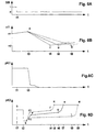
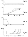
- 7B and 7D are three case examples shown, where the same line styles belong together.
- Figs. 7B and 7D as solid line runs a compromise between a sporty and a comfortable shift sequence
- Fig. 7B this corresponds to the curve with the points A and B.
- Fig. 7D this corresponds to the curve points E to H.
- the procedure is as follows:
- the electronic transmission control 13 gives time t1 the shift command SB to the automatic transmission.
- Fig. 7A the waveform changes from one to one Zero.
- the second clutch K2 up to the point in time t2 charged with the rapid filling pressure.
- a filling compensation phase follows until time t3, followed from a first pressure ramp, starting at point F and End point G.
- the pressure level of the first clutch K1 ramped down to zero.
- the transmission input speed nT begins to increase at point t3 in point A.
- the second clutch K2 the gradient of the transmission input speed is determined here.
- the transmission input speed reaches nT the synchronization point B of the second gear ratio. To this The point in time then becomes the pressure level of the second clutch K2 ramped up to the pressure level of point H elevated. This is reached at time t7, after that the circuit ended.
- the second case example, in Figs. 7B and 7D as Dotted line represents a circuit sequence with a sporty driving style. This corresponds to Fig. 7B the curve with points A and C. In Fig. 7D this corresponds to the curve with points E, F, J and K.
- the course is with the first Case example identical, so that what is described there applies.
- the second clutch K2 first pressure ramp start point F and end point J.
- This Pressure ramp has a larger slope than the pressure ramp of the first case study.
- the transmission input speed nT faster to the synchronization point C the second translation stage in other words: the Gradient of the transmission input speed is compared to that first case example increased.
- the second clutch becomes ramped at time t4 increased to the pressure level of point K. This is reached at time t5, then the circuit is ended.
- FIG. 7B The third case example, in Figs. 7B and 7D as Dotted line shows a comfortable Switching sequence represents.
- Fig. 7B this corresponds to the curve with points A and D.
- FIG. 7D the curve with points E, F, L and M.
- the second begins at time t3 Coupling K2 the first pressure ramp, start point F and end point L.
- This is the first pressure ramp of the second clutch K2 laid out very flat.
- Point A the transmission input speed nT less than in the first and second case studies, d. H. the gradient of the Gearbox input speed is therefore lower.
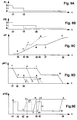
- 8B to 8E are two case examples shown, where the same line styles belong together.
- the first case example shown in FIGS. 8B to 8E as a solid line, represents a compromise between a sporty and a comfortable shift sequence.
- this corresponds to the curve with the points D1, E1 and F1.
- Fig. 8C this corresponds to the curve with the points A to D.
- Fig. 8D this corresponds to the curve H, J and K for the first disengaging clutch and the curve with the points H, L and M for the second disengaging clutch.
- Fig. 8E this corresponds to the curve with points S, T and U for the first closing clutch and the curve with points V, W and X for the second closing clutch.
- the driver desires a first downshift, as shown in FIG.
- the pressure level of the first clutch K1 is kept constant.
- the pressure profile of the first clutch K1 can also be designed to decrease slightly.
- the pressure level of the second clutch K2 is ramped up to the pressure level of the point U in accordance with the pressure level of the point T.
- the pressure level of point U is reached at time t5, so that the second clutch K2 can safely take over the load of the internal combustion engine at synchronous point B.
- the first downshift is completed at time t5.
- the electronic transmission control issues the shift command for the second downshift. This changes the signal level in Fig. 8B from one to zero.
- the pressure level of the first clutch K1 Due to the downshift command, the pressure level of the first clutch K1, this is the second clutch opening, is ramped down at point L. At the same time, for the second clutch K2, this is the second closing clutch, the quick filling phase, followed by a filling compensation phase, which ends at point W.
- the transmission input speed nT begins to increase in the direction of the new synchronization point D.
- the pressure level of the second clutch K2 is ramped up to the pressure level of point X, so that it can safely increase the load of the internal combustion engine at synchronization point D at time t8. Also at time t8, the first clutch K1 is switched off at point M. The circuit is then ended.
- a sporty shift sequence is shown in the second case example, drawn as a dashed line.
- Fig. 8B this corresponds to the curve with the points D1, D2 and F1.
- Fig. 8C this corresponds to the curve at points A, E, F and G.
- Fig. 8D this corresponds to curve H, N and O for the first opening clutch and curve H, P, Q and R for the second opening clutch.
- Fig. 8E this corresponds to the curve with points S, Y, Z and U for the first clutch to be engaged and the curve with points A1, B1 and C1 for the second clutch to be engaged. Up to time t2, the process is identical to that from the first case example.
- the negative pressure ramp started at point H is reduced to the pressure level of point N for the first clutch K1.
- the transmission input speed nT changes more rapidly at point A than in the first case example.
- the second clutch K2 is guided from the pressure level of point Y to the pressure level of point Z, so that it can safely take over the load of the internal combustion engine at the synchronization point at time t3.
- the first clutch K1 is switched off at point O.
- the electronic transmission control then issues the downshift command SB for the second downshift.
- the second clutch K2 is filled with the rapid filling pressure, pressure level corresponding to point A1.
- the pressure level of the first clutch K1 is reduced from point P to point Q. Due to the dead time of the hydraulics, the transmission input speed nT only begins to change in the direction of the new synchronizing point G at point t4 at point F. Shortly before the synchronization point G is reached, the pressure level of the second clutch K2 is increased from the pressure level of the point B1 to the point C1 in order to safely take over the load of the internal combustion engine at the synchronization point G. The synchronization point G is reached at time t6, so that the first clutch K1 can be switched off at point R. The circuit is then ended.
- the gradient can thus be the transmission input speed depending on the Driving activity between these two extreme curves, namely change A, B, C and D or A, E, F and G.
- FIGS. 9B to 9E Two case examples are shown in FIGS. 9B to 9E.
- the first case example drawn as a solid line, corresponds to the first case example of FIG. 8, so that there is no need to describe it again.
- the driver requests a second downshift.
- the signal level FL thereby changes from one to zero or the electronic transmission control issues the shift command SB.
- Figure 9B This is illustrated in Figure 9B in that the signal level changes from one to zero.
- the driving activity FA has increased in the period t1 to t3.
- the pressure level of the first clutch K1 at point N is ramped down to the pressure level of point O.
- the pressure level of the second clutch K2 is increased in a ramp shape in accordance with the line YZ, so that it can safely take over the load at the synchronization point F at time t4.
- the second clutch K2 that is to say the second clutch to be engaged, is filled with the rapid filling pressure, pressure level corresponding to point A1.
- the pressure level of the first clutch K1 here the second disengaging clutch, is reduced in point P to the pressure level of point Q.
- the transmission input speed nT changes after an actual time in the direction of the new synchronization point G.
- the pressure level of the second clutch K2 is led from the pressure level of the point B1 to the pressure level of the point C1, so that the load in Synchronization point G can safely take over.
- the synchronization point G is reached at the time t6, after which the switching is ended.
- FIGs 5 to 9 are controlled printing processes shown for the first and second clutch K1 and K2.
- the control process can be a control process be overlaid.
- the control procedure controls the gradient the transmission input speed nT.
- Fig. 5 C the first clutch K1, in FIG. 6D the second clutch K2, in Fig. 7D the second clutch K2 and in Fig. 8D the first Couplings K1 thus additionally regulated.
Landscapes
- Engineering & Computer Science (AREA)
- General Engineering & Computer Science (AREA)
- Mechanical Engineering (AREA)
- Physics & Mathematics (AREA)
- Fluid Mechanics (AREA)
- Control Of Transmission Device (AREA)
Applications Claiming Priority (3)
| Application Number | Priority Date | Filing Date | Title |
|---|---|---|---|
| DE19750447 | 1997-11-14 | ||
| DE19750447A DE19750447A1 (de) | 1997-11-14 | 1997-11-14 | Verfahren zum Steuern eines Automatgetriebes |
| PCT/EP1998/007137 WO1999025996A1 (de) | 1997-11-14 | 1998-11-09 | Verfahren zum steuern eines automatgetriebes |
Publications (2)
| Publication Number | Publication Date |
|---|---|
| EP1030984A1 EP1030984A1 (de) | 2000-08-30 |
| EP1030984B1 true EP1030984B1 (de) | 2001-05-09 |
Family
ID=7848710
Family Applications (1)
| Application Number | Title | Priority Date | Filing Date |
|---|---|---|---|
| EP98959862A Expired - Lifetime EP1030984B1 (de) | 1997-11-14 | 1998-11-09 | Verfahren zum steuern eines automatgetriebes |
Country Status (6)
| Country | Link |
|---|---|
| US (1) | US6375597B1 (enExample) |
| EP (1) | EP1030984B1 (enExample) |
| JP (1) | JP2001523798A (enExample) |
| KR (1) | KR100561033B1 (enExample) |
| DE (2) | DE19750447A1 (enExample) |
| WO (1) | WO1999025996A1 (enExample) |
Families Citing this family (18)
| Publication number | Priority date | Publication date | Assignee | Title |
|---|---|---|---|---|
| DE19961979A1 (de) * | 1999-12-22 | 2001-08-09 | Zahnradfabrik Friedrichshafen | Kick-down-Schaltdrehzahloptimierung für ein Automatgetriebe eines Kraftfahrzeugs |
| JP4062848B2 (ja) * | 2000-02-23 | 2008-03-19 | アイシン・エィ・ダブリュ株式会社 | 自動変速機の制御装置 |
| DE10057089A1 (de) * | 2000-11-17 | 2002-05-23 | Zahnradfabrik Friedrichshafen | Verfahren zur Erhöhung der Bremswirkung |
| US6869382B2 (en) * | 2003-05-07 | 2005-03-22 | Daimlerchrysler Corporation | Double-downshift gear strategy for a dual clutch automatic transmission |
| DE102004001381A1 (de) * | 2004-01-09 | 2005-08-04 | Zf Friedrichshafen Ag | Verfahren zur Erhöhung der Spontanität von Überschneidungsschaltungen in einem Automatgetriebe |
| DE102004010269A1 (de) * | 2004-03-03 | 2005-09-22 | Zf Friedrichshafen Ag | Verfahren zur Gestaltung der Schaltgeschwindigkeit von Automatgetrieben |
| DE102006012341A1 (de) * | 2006-03-17 | 2007-09-20 | Zf Friedrichshafen Ag | Verfahren zum Betrieb eines hydraulisch betätigbaren Schaltelements |
| DE102006014941A1 (de) | 2006-03-31 | 2007-05-24 | Zf Friedrichshafen Ag | Verfahren zum Betreiben eines Automatgetriebes |
| DE102006014947A1 (de) | 2006-03-31 | 2007-10-04 | Zf Friedrichshafen Ag | Verfahren zum Betreiben eines Automatgetriebes |
| DE102006014946A1 (de) | 2006-03-31 | 2007-03-29 | Zf Friedrichshafen Ag | Verfahren zum Betreiben eines Automatgetriebes |
| DE102006026602B4 (de) * | 2006-06-08 | 2020-07-09 | Zf Friedrichshafen Ag | Verfahren zum Betreiben eines Antriebsstrangs |
| DE102006026596A1 (de) * | 2006-06-08 | 2007-12-13 | Zf Friedrichshafen Ag | Verfahren zum Betreiben eines Antriebsstrangs |
| DE102007018156A1 (de) | 2007-04-18 | 2008-10-23 | Zf Friedrichshafen Ag | Verfahren zum Betreiben eines Antriebsstrangs |
| JP4360421B2 (ja) * | 2007-05-15 | 2009-11-11 | トヨタ自動車株式会社 | 自動変速機の変速制御装置 |
| US8000864B2 (en) * | 2008-02-22 | 2011-08-16 | Allison Transmission, Inc. | System and method for changing values stored in memory that relate to the operation of an automatic transmission |
| JP5330470B2 (ja) * | 2011-08-31 | 2013-10-30 | 本田技研工業株式会社 | 変速機の制御装置 |
| KR101339232B1 (ko) * | 2011-11-29 | 2013-12-09 | 현대자동차 주식회사 | 자동변속기의 유압제어장치 및 그 방법 |
| JP6152593B2 (ja) * | 2013-11-13 | 2017-06-28 | ジヤトコ株式会社 | 自動変速機の制御装置 |
Family Cites Families (16)
| Publication number | Priority date | Publication date | Assignee | Title |
|---|---|---|---|---|
| DE3334718A1 (de) * | 1983-09-26 | 1985-04-04 | Wabco Westinghouse Fahrzeugbremsen GmbH, 3000 Hannover | Getriebesteuerung fuer ein strassenfahrzeug |
| JP2702703B2 (ja) * | 1986-06-30 | 1998-01-26 | アイシン・エィ・ダブリュ株式会社 | ロツクアツプクラツチ付自動変速機 |
| JP2767793B2 (ja) * | 1987-04-20 | 1998-06-18 | 三菱自動車工業株式会社 | 自動変速装置の入力パワーオンオフ判定方法 |
| JPS6444394A (en) * | 1987-08-11 | 1989-02-16 | Honda Motor Co Ltd | Controller for non-stage transmission |
| US4975845A (en) | 1988-04-29 | 1990-12-04 | Chrysler Corporation | Method of operating an electronic automatic transmission system |
| DE3922051A1 (de) | 1989-07-05 | 1991-01-24 | Porsche Ag | Verfahren und vorrichtung zur steuerung eines selbsttaetig schaltenden getriebes |
| US5014573A (en) * | 1989-12-11 | 1991-05-14 | General Motors Corporation | Double transition upshift control in an automatic transmission |
| DE3941999C2 (de) * | 1989-12-20 | 1997-03-20 | Bayerische Motoren Werke Ag | Verfahren zum Ermitteln eines Fahrerfaktors |
| US5072390A (en) * | 1989-12-26 | 1991-12-10 | General Motors Corporation | Adaptive control of an automatic transmission |
| US5036729A (en) * | 1990-10-23 | 1991-08-06 | Saturn Corporation | Coast-sync-coast downshift control method for clutch-to-clutch transmission shifting |
| US5445577A (en) | 1992-04-15 | 1995-08-29 | Mitsubishi Jidosha Kogyo Kabushiki Kaisha | Method and apparatus for speed change control of an automatic transmission |
| DE4409122C2 (de) * | 1993-08-10 | 1998-12-24 | Porsche Ag | Vorrichtung und Verfahren zum Regeln einer Kupplung eines Fahrzeugantriebes |
| JP3956156B2 (ja) * | 1995-03-16 | 2007-08-08 | アイシン・エィ・ダブリュ株式会社 | 自動変速機の変速制御装置 |
| JP3627276B2 (ja) * | 1995-03-16 | 2005-03-09 | アイシン・エィ・ダブリュ株式会社 | 自動変速機の変速制御装置 |
| JP2878994B2 (ja) | 1995-08-31 | 1999-04-05 | アイシン・エィ・ダブリュ株式会社 | 自動変速機の制御装置 |
| JP3298423B2 (ja) * | 1996-09-19 | 2002-07-02 | アイシン・エィ・ダブリュ株式会社 | 自動変速機の油圧制御装置 |
-
1997
- 1997-11-14 DE DE19750447A patent/DE19750447A1/de not_active Withdrawn
-
1998
- 1998-11-09 US US09/554,355 patent/US6375597B1/en not_active Expired - Lifetime
- 1998-11-09 DE DE59800704T patent/DE59800704D1/de not_active Expired - Lifetime
- 1998-11-09 KR KR1020007005247A patent/KR100561033B1/ko not_active Expired - Lifetime
- 1998-11-09 WO PCT/EP1998/007137 patent/WO1999025996A1/de not_active Ceased
- 1998-11-09 EP EP98959862A patent/EP1030984B1/de not_active Expired - Lifetime
- 1998-11-09 JP JP2000521328A patent/JP2001523798A/ja active Pending
Also Published As
| Publication number | Publication date |
|---|---|
| JP2001523798A (ja) | 2001-11-27 |
| KR100561033B1 (ko) | 2006-03-16 |
| US6375597B1 (en) | 2002-04-23 |
| WO1999025996A1 (de) | 1999-05-27 |
| KR20010032109A (ko) | 2001-04-16 |
| DE19750447A1 (de) | 1999-06-02 |
| EP1030984A1 (de) | 2000-08-30 |
| DE59800704D1 (de) | 2001-06-13 |
Similar Documents
| Publication | Publication Date | Title |
|---|---|---|
| EP1030984B1 (de) | Verfahren zum steuern eines automatgetriebes | |
| EP0670789B1 (de) | Verfahren zur steuerung des abtriebsmoments eines automatischen schaltgetriebes | |
| EP1899190B1 (de) | Verfahren zum steuern eines antriebsstranges eines fahrzeugs mit einer antriebsmaschine und mit einem getriebe | |
| EP0380564B1 (de) | Verfahren und vorrichtung zur steuerung eines kraftfahrzeug-antriebstranges | |
| EP0588896B1 (de) | Verfahren zur steuerung eines automatisch betätigten getriebes eines kraftfahrzeugs | |
| EP0676564B1 (de) | Steuereinrichtung und Steuerverfahren für ein stufenloses Getriebe | |
| EP0589919B1 (de) | Verfahren zur steuerung eines stufenlosen getriebes eines kraftfahrzeugs | |
| EP1448403A1 (de) | System und verfahren zur vorgabe eines motordrehmomentes und einer getriebeübersetzung bei einem fahrzeug mit kontinuierlich verstellbarem getriebe | |
| DE102004058206A1 (de) | Verzögerungssteuervorrichtung und Verzögerungssteuerverfahren für ein Fahrzeug | |
| WO1993000229A1 (de) | Verfahren zur steuerung eines stufenlosen getriebes eines kraftfahrzeugs | |
| DE3139838A1 (de) | Verfahren zum steuern von automatischen stufengetrieben in kraftfahrzeugen | |
| EP0974019B1 (de) | Erhöhung der spontanität eines automatgetriebes | |
| DE4441878A1 (de) | Steuereinrichtung und Steuerverfahren für ein stufenloses Getriebe | |
| DE10145204B4 (de) | Verfahren und Vorrichtung zur Steuerung des Antriebsstrangs eines Kraftfahrzeugs | |
| EP0985107B1 (de) | Erhöhung der spontanität eines automatgetriebes | |
| EP0728612A2 (de) | Regeleinrichtung für ein stufenlos einstellbares Getriebe für Kraftfahrzeuge | |
| EP1543259B1 (de) | Erhöhung der spontanität eines automatgetriebes | |
| EP0974018B1 (de) | Erhöhung der spontaneität eines automatgetriebes | |
| EP0939868A1 (de) | Erhöhung der spontanität eines automatgetriebes | |
| DE10231210A1 (de) | Verfahren zum Steuern einer Kraftfahrzeugantriebsvorrichtung | |
| DE10102016A1 (de) | Verfahren zur Regelung des Schaltvorganges eines Kraftfahrzeuges | |
| DE4446111A1 (de) | Verfahren und Anordnung zur Beeinflussung von Schaltpunkten in Abhängigkeit von eingeschalteten Motorbremsprogrammen | |
| DE4333589A1 (de) | Vorrichtung zur Reduzierung des Brennkraftmaschinenmoments bei Hochschaltvorgängen | |
| EP1224412A1 (de) | Verfahren und vorrichtung zum steuern und regeln einer kupplung in einem gestuften lastschaltbaren automatgetriebe | |
| WO2002055330A1 (de) | Verfahren zur steuerung eines antriebsstrangbauteils eines kraftfahrzeugs, insbesondere einer brennkraftmaschine |
Legal Events
| Date | Code | Title | Description |
|---|---|---|---|
| PUAI | Public reference made under article 153(3) epc to a published international application that has entered the european phase |
Free format text: ORIGINAL CODE: 0009012 |
|
| 17P | Request for examination filed |
Effective date: 20000408 |
|
| AK | Designated contracting states |
Kind code of ref document: A1 Designated state(s): DE FR GB IT |
|
| GRAG | Despatch of communication of intention to grant |
Free format text: ORIGINAL CODE: EPIDOS AGRA |
|
| GRAG | Despatch of communication of intention to grant |
Free format text: ORIGINAL CODE: EPIDOS AGRA |
|
| GRAH | Despatch of communication of intention to grant a patent |
Free format text: ORIGINAL CODE: EPIDOS IGRA |
|
| 17Q | First examination report despatched |
Effective date: 20000922 |
|
| GRAH | Despatch of communication of intention to grant a patent |
Free format text: ORIGINAL CODE: EPIDOS IGRA |
|
| ITF | It: translation for a ep patent filed | ||
| GRAA | (expected) grant |
Free format text: ORIGINAL CODE: 0009210 |
|
| AK | Designated contracting states |
Kind code of ref document: B1 Designated state(s): DE FR GB IT |
|
| REF | Corresponds to: |
Ref document number: 59800704 Country of ref document: DE Date of ref document: 20010613 |
|
| ET | Fr: translation filed | ||
| GBT | Gb: translation of ep patent filed (gb section 77(6)(a)/1977) |
Effective date: 20010730 |
|
| REG | Reference to a national code |
Ref country code: GB Ref legal event code: IF02 |
|
| PLBE | No opposition filed within time limit |
Free format text: ORIGINAL CODE: 0009261 |
|
| STAA | Information on the status of an ep patent application or granted ep patent |
Free format text: STATUS: NO OPPOSITION FILED WITHIN TIME LIMIT |
|
| 26N | No opposition filed | ||
| PG25 | Lapsed in a contracting state [announced via postgrant information from national office to epo] |
Ref country code: IT Free format text: LAPSE BECAUSE OF NON-PAYMENT OF DUE FEES Effective date: 20051109 |
|
| PGFP | Annual fee paid to national office [announced via postgrant information from national office to epo] |
Ref country code: GB Payment date: 20101103 Year of fee payment: 13 |
|
| PGFP | Annual fee paid to national office [announced via postgrant information from national office to epo] |
Ref country code: FR Payment date: 20111118 Year of fee payment: 14 |
|
| GBPC | Gb: european patent ceased through non-payment of renewal fee |
Effective date: 20121109 |
|
| REG | Reference to a national code |
Ref country code: FR Ref legal event code: ST Effective date: 20130731 |
|
| PG25 | Lapsed in a contracting state [announced via postgrant information from national office to epo] |
Ref country code: FR Free format text: LAPSE BECAUSE OF NON-PAYMENT OF DUE FEES Effective date: 20121130 Ref country code: GB Free format text: LAPSE BECAUSE OF NON-PAYMENT OF DUE FEES Effective date: 20121109 |
|
| PGFP | Annual fee paid to national office [announced via postgrant information from national office to epo] |
Ref country code: DE Payment date: 20171031 Year of fee payment: 20 |
|
| REG | Reference to a national code |
Ref country code: DE Ref legal event code: R071 Ref document number: 59800704 Country of ref document: DE |