EP1030617B1 - Dispositif de manipulation d'instruments chirurgicaux - Google Patents
Dispositif de manipulation d'instruments chirurgicaux Download PDFInfo
- Publication number
- EP1030617B1 EP1030617B1 EP98954075A EP98954075A EP1030617B1 EP 1030617 B1 EP1030617 B1 EP 1030617B1 EP 98954075 A EP98954075 A EP 98954075A EP 98954075 A EP98954075 A EP 98954075A EP 1030617 B1 EP1030617 B1 EP 1030617B1
- Authority
- EP
- European Patent Office
- Prior art keywords
- movement
- axis
- patient
- rail
- around
- Prior art date
- Legal status (The legal status is an assumption and is not a legal conclusion. Google has not performed a legal analysis and makes no representation as to the accuracy of the status listed.)
- Expired - Lifetime
Links
- 210000003811 finger Anatomy 0.000 claims description 4
- 210000003813 thumb Anatomy 0.000 claims description 2
- 238000005096 rolling process Methods 0.000 claims 2
- 238000006073 displacement reaction Methods 0.000 description 6
- 238000001356 surgical procedure Methods 0.000 description 4
- 230000003187 abdominal effect Effects 0.000 description 3
- 210000004247 hand Anatomy 0.000 description 2
- 230000035515 penetration Effects 0.000 description 2
- 230000000007 visual effect Effects 0.000 description 2
- 238000012800 visualization Methods 0.000 description 2
- 240000008042 Zea mays Species 0.000 description 1
- 230000004308 accommodation Effects 0.000 description 1
- 230000004424 eye movement Effects 0.000 description 1
- 230000007935 neutral effect Effects 0.000 description 1
- 230000000399 orthopedic effect Effects 0.000 description 1
- 230000002441 reversible effect Effects 0.000 description 1
- 230000006641 stabilisation Effects 0.000 description 1
- 238000011105 stabilization Methods 0.000 description 1
- 210000002784 stomach Anatomy 0.000 description 1
Images






Classifications
-
- A—HUMAN NECESSITIES
- A61—MEDICAL OR VETERINARY SCIENCE; HYGIENE
- A61B—DIAGNOSIS; SURGERY; IDENTIFICATION
- A61B90/00—Instruments, implements or accessories specially adapted for surgery or diagnosis and not covered by any of the groups A61B1/00 - A61B50/00, e.g. for luxation treatment or for protecting wound edges
- A61B90/50—Supports for surgical instruments, e.g. articulated arms
-
- A—HUMAN NECESSITIES
- A61—MEDICAL OR VETERINARY SCIENCE; HYGIENE
- A61B—DIAGNOSIS; SURGERY; IDENTIFICATION
- A61B34/00—Computer-aided surgery; Manipulators or robots specially adapted for use in surgery
- A61B34/70—Manipulators specially adapted for use in surgery
- A61B34/74—Manipulators with manual electric input means
- A61B2034/743—Keyboards
-
- A—HUMAN NECESSITIES
- A61—MEDICAL OR VETERINARY SCIENCE; HYGIENE
- A61B—DIAGNOSIS; SURGERY; IDENTIFICATION
- A61B34/00—Computer-aided surgery; Manipulators or robots specially adapted for use in surgery
- A61B34/70—Manipulators specially adapted for use in surgery
Definitions
- the present invention relates to a device that allows the manipulation, i.e. the positioning and moving, of instruments surgical, such as an endoscope, during an operation surgical.
- WO95 / 16396 describes a device manipulating a surgical instrument using several successive arms which rotate around vertical axes as proposed above, and which, by a complex and detailed calculation of the different movements of the actuators, will provide a incremental displacement of the scope head. However, these movements are obtained by three changes of successive Cartesian coordinates, which makes the relatively complex visualization of movements.
- a voice command can also be proposed. However, this voice command does not allow carrying out small rapid movements and / or high rate.
- the present invention aims to provide a surgical instrument handling device which either a relatively simple design and a the smallest possible footprint.
- Another object of the present invention is to propose a device which makes it possible to free as much as possible the surgeon's hands.
- Another object of the present invention is to reduce field size as much as possible action of the surgeon.
- Another object of the present invention is to propose a device that allows a combination of simple movements reproducing the three movements fundamentals of exploring the visual field.
- Another object of the present invention is to offer a control device that is simple and very space-saving, so that it allows manipulation of other instruments.
- first and second movements are carried out around axes essentially horizontal especially when the plane in which the patient is arranged is himself horizontal.
- the two horizontal axes are parallel to each other, and their projection in the plane of the patient are orthogonal to the patient's axis.
- the first and second movable elements are in the form of arms articulated while the deformable element is present under the shape of a deformable and articulated quadrilateral.
- the second articulated mobile element has two articulation points, one of which can slide in one slide and the other of which can be blocked or free.
- the gripping element is arranged in a slide secured to the deformable element.
- the support element is fixed to a rail secured to the operating table using a device of fixation.
- this fixing device comprises at least two boxes which make a first orthogonal movement to the bed of the patient and a second longitudinal movement parallel to the patient bed.
- a screw allows the movement of the first box in the second box so as to obtain the first movement which is orthogonal to the patient's bed.
- the second movement which is longitudinal is carried out at using a third box which includes bearings that slide on a slide. Fixing the device is carried out when one or more screws are tightened claiming the rail between the claims and a suitable element.
- the longitudinal movement is achieved using several, and preferably four bearings using the rail of the operating table as a slide, a lower clam which allows, by means of a wheel, to immobilize the assembly on said rail.
- the fixing device can be reversed by rotation around a vertical axis and is adjusted by sliding along the fixing rail secured to the operating table.
- the manipulator includes a control consisting of a mini-keyboard with at least six keys for two or three fingers, and the inner part of which is triangular.
- This control device is completely autonomous and has a transmitter that transmits commands to the main unit, this transmitter in the form of a small shaped box triangular.
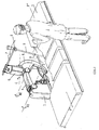
- the handling device according to the present invention and shown in Figure 1 in perspective is integral with the bed on which the patient goes go to bed.
- This manipulator has the advantage particular that it has a displacement field such as it can be applied to two large families surgical operations: on the one hand gynecological surgeries and secondly abdominal surgical procedures. It suffices, to go from one field to another, to simply return the device with respect to a vertical plane which is perpendicular to the axis along which the patient is lying. This means that the device is of course reversible and that it is enough to orient it according to the front position or back to the patient.
- Figure 2 shows more precisely the device arranged to allow intervention gynecological type. This basically means that the endoscope will enter the patient in a position such as this provides a visualization of the field where the surgeon will have to intervene.
- Figure 3 shows the device arranged so as to allow an abdominal type intervention.
- the endoscope will enter the patient in a position such as this allows viewing towards the patient's head.
- the patient's body is arranged along an axis PP 'with the patient's head directed towards P '.
- O represents the point of penetration of the instrument in the patient's womb. This point represents usually the patient's navel.
- the manipulator therefore makes it possible to move a instrument (9) by movements around two axes (H1 and H2) of rotation parallel to each other and to the bed of the patient as well as around a third axis (C) of rotation.
- the first rotational movement is not done around a axis perpendicular to the operating table and more particularly vertical. This therefore allows clear the field in a particularly advantageous way action of the surgeon.
- This execution ensures the ⁇ and ⁇ movements by means of a single servomotor.
- the gripping arm (7) is always horizontal. This allows to limit as much as possible the space created by it in the field of action of the surgeon. It is connected to the patient's mechanism and bed from the side opposite the surgeon.
- the surgical instrument (9), such as a endoscope, is connected to the gripping arm (7) by through a passive (non-motorized) seal so to reproduce the image that the latter perceives and that it is always oriented correctly with respect to the axes of reference of the room, that is to say that the directions vertical should appear as vertical on the monitor.
- the rotation of the second arm (5) and the deformation of the articulated parallelogram (6) are provided by two servomotors incorporated in the arm (5).
- Attaching the scope (9) to the arm of gripping (7) in S ' can be ensured by means of a seal liability consisting of at least two articulated parts according to the axis (j) perpendicular to the axis (d) of the gripping arm (7) and to SS '.
- the part holding the scope is fixed to this last in a position such as the landmark of verticality of the image either in the vertical passing plane by (j). In this way, the image of the scope will appear always vertical for a fictitious observer located at the head of the patient and looking parallel to the axis PP '.
- the piece attached to the gripping arm (7) in S ' is clipped onto this gripping arm (7) so as to ability to rotate freely around axis (d).
- This piece is designed to be unclipped from the arm grip (7) by simple action on a small lever.
- this set can be validly made in one piece of material elastic.
- the manipulator control device can consist of a six-key mini-keyboard for two or three fingers (auricular and annular, and middle finger for the three-finger version) placed in the hollow of the practitioner's hand using adequate forceps surrounding the practitioner's hand, characterized in that the part inside (in the palm of your hand), shaped triangular, fits in the "trapezoid" of the hand, between the thenar eminence and the fold of the four phalanges, do not thus in no way impeding the movements of the hand.
- the gripping arm (7) of the instrument (9) can be adjusted in a slide (71) so as to arrange S 'and therefore S so that they are located in the POP 'plan.
- the manipulator can be adapted to one of the other type of operation: abdominal or gynecological (see figures 1 and 2) simply by turning it 180 ° from fixing device and by inverting then adjusting the gripping arm (7) in its slide (71).
- the manipulator is fixed to a rail (2) itself secured to the operating table (3) using a fixing device (100).
- This device (100) therefore makes it possible to precisely adjust the position of the support (1) longitudinally (parallel to the rail (2) of the operating table (3)) and vertically (or more generally perpendicular to the plane in which the patient is ready).
- This device essentially comprises two boxes (101 and 102) made from folded sheets and welded together, which are closed and intended to stiffen the attachment of the device according to the invention.
- the first box (101) makes it possible to fix the support (1) in tightening two thumbscrews (105).
- This box is integral of two nuts (103).
- a screw (104) which can be operated manually or even be motorized, allows movement of the box (101) inside the second box (102) when the screw (104) is turned. This allows perform the vertical movement.
- the originality of this feature lies in the characteristic that the two boxes (101 and 102) slide with significant play of fact that these are made using folded sheets and welded not machined. This game will be canceled by joining the particularly rigidly by tightening the two thumbscrews (105) in the support (1) when the desired vertical position is reached.
- the horizontal movement is carried out using two nuts (109) integral with the box (102).
- a screw (110) allows the whole support (1) to be moved, integral with the two boxes (101 and 102), parallel to the rail (2) from the operating table to the position required.
- a box (106) also made of sheets folded and welded is provided, and which includes two clamps (111) attached to the rail (2) of the operating table, is also planned.
- Bearings (113) also attached to the box (102) slide on a slide (112) supporting the support assembly (1) and boxes (101 and 102) at the during the longitudinal displacement.
- the originality of this device allows that when the screw (108) is tightened, clamps the rail (2) between the clamps (111) and the element (107). Simultaneously, the nuts (109) are locked between the box (106) and the same element (107), canceling the play important of these non-machined parts and thus making everything all particularly rigid.
- the rail (2) as a slide in providing four orthogonal bearings (121) in the upper part of the rail (2).
- the lower claim (122) is released (in position A as shown in the figure 10)
- the lower part of the rail (2) is supported directly on a thumbwheel (123) actuable by a geared motor (124).
- This wheel (123) allows the movement along the rail (2).
- the cry lower (122) is locked by means of the thumb wheel (125) and its screw (in position B as shown more in details in figure 11), the support assembly (1) will be fully immobilized, the gear motor (124) and its wheel (123) being released.
Landscapes
- Health & Medical Sciences (AREA)
- Surgery (AREA)
- Life Sciences & Earth Sciences (AREA)
- Engineering & Computer Science (AREA)
- Molecular Biology (AREA)
- Public Health (AREA)
- Veterinary Medicine (AREA)
- Biomedical Technology (AREA)
- Heart & Thoracic Surgery (AREA)
- Medical Informatics (AREA)
- Nuclear Medicine, Radiotherapy & Molecular Imaging (AREA)
- Animal Behavior & Ethology (AREA)
- General Health & Medical Sciences (AREA)
- Pathology (AREA)
- Oral & Maxillofacial Surgery (AREA)
- Robotics (AREA)
- Accommodation For Nursing Or Treatment Tables (AREA)
- Manipulator (AREA)
- Surgical Instruments (AREA)
- Fixing For Electrophotography (AREA)
- Endoscopes (AREA)
Description
- un premier élément mobile articulé à l'élément support fixe autour d'un premier axe essentiellement parallèle au plan dans lequel est disposé le patient, générant ainsi un premier mouvement;
- un second élément mobile articulé à l'extrémité du premier élément autour d'un deuxième axe essentiellement parallèle au plan dans lequel est disposé le patient, générant ainsi un second mouvement;
- un troisième élément déformable fixé par un côté à l'extrémité du deuxième élément mobile et susceptible d'effectuer un troisième mouvement de rotation autour d'un troisième axe;
- un élément de préhension fixé du côté opposé à celui du deuxième élément à l'élément déformable;
- un dispositif d'accrochage d'un instrument chirurgical à l'élément de préhension; et
- des moyens d'action permettant d'effectuer des mouvements de rotation autour des différents axes.
- La figure 1
- représente une vue en perspective de la table d'opération sur laquelle le patient sera couché et à laquelle est fixé le dispositif de manipulation selon la présente invention.
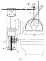
- Les figures 2 et 3
- représentent une vue en coupe latérale du dispositif de manipulation d'instruments chirurgicaux selon la présente invention pour deux applications d'interventions chirurgicales.
- Les figures 4 et 5
- représentent des vues en coupe frontale du dispositif tel que représenté aux figures 2 et 3.
- La figure 6
- représente une vue en coupe latérale correspondant à la figure 2 mais permettant de visualiser les différents mouvements du manipulateur.
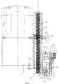
- Les figures 7 et 8
- représentent une vue en coupe latérale et une vue en coupe par le dessus d'un dispositif de fixation permettant de fixer le manipulateur au lit du patient selon une première forme d'exécution.
- Les figures 9, 10 et 11
- représentent une seconde forme d'exécution du dispositif de fixation du manipulateur au lit du patient.
- un support (1) (après ajustement en hauteur et
longitudinalement) sera fixé sur un rail (2) solidaire de
la table d'opération (3), ce support fixé étant associé
à :
- un premier bras mobile (4) articulé au support fixé autour d'un axe essentiellement horizontal H1 perpendiculaire au plan vertical passant par l'axe longitudinal du patient POP' ;
- un deuxième bras mobile (5) articulé à l'extrémité du premier autour d'un deuxième axe essentiellement horizontal H2, également perpendiculaire au même plan POP' ;
- un élément déformable (6) fixé par un côté à l'extrémité du deuxième bras (5) et susceptible d'effectuer un mouvement de rotation autour d'un axe C;
- un bras de préhension (7) horizontal fixé au côté opposé du quadrilatère (6) ;
- un dispositif d'accrochage (8) d'un instrument (9) au bras de préhension (7) ;
- des actionneurs qui permettent d'exécuter des mouvements de rotation autour des différents axes mentionnés H1, H2 et C;
- des moyens de pilotage et de synchronisation de ces mouvements; et
- une commande placée dans le creux de la main du praticien, lui permettant, au moyen de plusieurs touches, d'accéder aux différents mouvements.
| Mouvements de l'oeil | Mouvement donné au scope | ||
| Direction | Sens | Symbole (+ sens) | |
| Accommodation (proche/lointain) | Zoom | in/out | ζ (i/o) |
| Rotation verticale (haut / bas) | Rotation | haut/bas | ρ (h/b) |
| Rotation horizontale (gauche / droite) | Latéral | gauche/droite | λ (g/d) |
Deux cas de figure peuvent se présenter :
- l'articulation (B) est bloquée : les bras et éléments (5, 6 et 7) sont donc simplement entraínés par la rotation du support (1) autour de l'axe H1, et le mouvement de S' et S est donc voisin de ρ;
- l'articulation (B) est libre, mais la position de (B') dans sa glissière est bloquée par un solénoïde (52) : dans ce cas, le mouvement du parallélogramme (6) entraíné par la rotation du support (1) autour de l'axe H1 induit un déplacement du bras de préhension (7), et donc de S' et S, voisin de ζ.
Claims (11)
- Dispositif de manipulation d'un instrument chirurgical, comprenant un support fixe (1), un premier élément mobile (4) lié audit support fixe (1), un deuxième élément mobile (5) articulé à l'une des extrémités du premier élément mobile (4) et un dispositif d'accrochage (8) d'un instrument chirurgical (9), caractérisé en ce que :et en ce qu'il comprend en outre :le premier élément mobile (4) est articulé au support fixe (1) autour d'un premier axe (H1) essentiellement parallèle au plan dans lequel est disposé le patient (PP') et susceptible d'effectuer un premier mouvement;le second élément mobile (5) est articulé à l'extrémité du premier élément mobile (4) autour d'un deuxième axe (H2) essentiellement parallèle au plan dans lequel est disposé le patient (PP') et susceptible d'effectuer un deuxième mouvement;un élément déformable (6) fixé par un côté à l'extrémité du deuxième élément mobile (5) et susceptible d'effectuer un troisième mouvement de rotation autour d'un troisième axe (C);un élément de préhension (7) fixé du côté opposé à celui du deuxième élément à l'élément déformable (6) et auquel est fixé le dispositif d'accrochage (8); etdes moyens d'action (10 et 11) permettant d'effectuer des mouvements de rotation autour des différents axes (H1, H2 et C) .
- Dispositif selon la revendication 1, caractérisé en ce que les premier (4) et deuxième (5) éléments mobiles se présentent sous forme de bras articulés, tandis que l'élément déformable (6) se présente sous la forme d'un quadrilatère déformable et articulé.
- Dispositif selon la revendication 2, caractérisé en ce que le deuxième élément mobile (5) présente un point d'articulation qui peut coulisser dans une glissière (51) solidaire de l'élément déformable (6) tandis que l'autre point d'articulation peut être soit bloqué, soit libre.
- Dispositif selon l'une quelconque des revendications précédentes, caractérisé en ce que l'élément de préhension (7) est disposé dans une glissière (71) solidaire de l'élément déformable (6).
- Dispositif selon l'une quelconque des revendications précédentes, caractérisé en ce que l'élément support (1) est fixé à un rail (2) solidaire de la table d'opération (3) à l'aide d'un dispositif de fixation (100).
- Dispositif selon la revendication 5, caractérisé en ce que le dispositif de fixation (100) comprend deux caissons (101 et 102) effectuant deux mouvements, un mouvement orthogonal au plan dans lequel est disposé le patient (PP') et un mouvement parallèle au plan du patient PP', le mouvement orthogonal étant réalisé à l'aide d'une vis (104) permettant l'introduction du premier caisson (101) dans le second caisson (102), le mouvement longitudinal étant réalisé à l'aide d'un troisième caisson (106) qui comprend des roulements (113) qui coulissent sur une glissière (112), la fixation du dispositif est réalisée lorsque l'on serre une ou plusieurs vis (108) en clamant le rail (2) entre les clames (111) et un élément adéquat (107).
- Dispositif selon la revendication 5 ou 6, caractérisé en ce que le mouvement longitudinal est réalisé à l'aide de plusieurs, et de préférence quatre roulements (121) utilisant le rail (2) comme glissière, une clame inférieure (122) qui permet, au moyen d'une molette (125), d'immobiliser l'ensemble sur ledit rail (2).
- Dispositif selon l'une quelconque des revendications précédentes 5 à 7, caractérisé en ce que le dispositif de fixation (100) est inversé par rotation autour d'un axe vertical et est ajusté par glissement le long du rail de fixation (26a) solidaire de la table d'opération (26).
- Dispositif selon l'une quelconque des revendications précédentes, caractérisé en ce que le moyen d'accrochage (8) de l'instrument chirurgical (9) à l'élément de préhension (7) est constitué par un joint passif comprenant lui-même au moins deux pièces articulées selon deux axes perpendiculaires d'une part à l'axe de l'instrument chirurgical (9) et d'autre part à l'axe du premier élément (4), et dans lequel l'instrument chirurgical est fixé dans une position telle que le repère de verticalité de l'image dans le plan vertical soit assuré.
- Dispositif selon l'une quelconque des revendications précédentes, caractérisé en ce qu'il comprend un dispositif de commande (50) constitué d'un mini-clavier (51) à au moins six touches (52) pour deux ou trois doigts, et dont la partie intérieure est de forme triangulaire.
- Dispositif selon la revendication 10, caractérisé en ce que le dispositif de commande est complètement autonome et comporte un émetteur qui transmet les commandes au boítier principal, cet émetteur se présentant sous la forme d'un petit boítier de forme triangulaire.
Priority Applications (1)
| Application Number | Priority Date | Filing Date | Title |
|---|---|---|---|
| EP98954075A EP1030617B1 (fr) | 1997-11-14 | 1998-11-16 | Dispositif de manipulation d'instruments chirurgicaux |
Applications Claiming Priority (4)
| Application Number | Priority Date | Filing Date | Title |
|---|---|---|---|
| EP97870183 | 1997-11-14 | ||
| EP97870183A EP0917859A1 (fr) | 1997-11-14 | 1997-11-14 | Dispositif de manipulation d'instruments chirurgicaux |
| EP98954075A EP1030617B1 (fr) | 1997-11-14 | 1998-11-16 | Dispositif de manipulation d'instruments chirurgicaux |
| PCT/BE1998/000177 WO1999025267A1 (fr) | 1997-11-14 | 1998-11-16 | Dispositif de manipulation d'instruments chirurgicaux |
Publications (2)
| Publication Number | Publication Date |
|---|---|
| EP1030617A1 EP1030617A1 (fr) | 2000-08-30 |
| EP1030617B1 true EP1030617B1 (fr) | 2003-05-21 |
Family
ID=8231066
Family Applications (2)
| Application Number | Title | Priority Date | Filing Date |
|---|---|---|---|
| EP97870183A Withdrawn EP0917859A1 (fr) | 1997-11-14 | 1997-11-14 | Dispositif de manipulation d'instruments chirurgicaux |
| EP98954075A Expired - Lifetime EP1030617B1 (fr) | 1997-11-14 | 1998-11-16 | Dispositif de manipulation d'instruments chirurgicaux |
Family Applications Before (1)
| Application Number | Title | Priority Date | Filing Date |
|---|---|---|---|
| EP97870183A Withdrawn EP0917859A1 (fr) | 1997-11-14 | 1997-11-14 | Dispositif de manipulation d'instruments chirurgicaux |
Country Status (15)
| Country | Link |
|---|---|
| US (1) | US6409735B1 (fr) |
| EP (2) | EP0917859A1 (fr) |
| JP (1) | JP4094225B2 (fr) |
| KR (1) | KR100555257B1 (fr) |
| AT (1) | ATE240687T1 (fr) |
| AU (1) | AU751225B2 (fr) |
| BR (1) | BR9814186A (fr) |
| CA (1) | CA2309181C (fr) |
| DE (1) | DE69814906T2 (fr) |
| ES (1) | ES2198761T3 (fr) |
| IL (1) | IL136130A (fr) |
| NO (1) | NO20002291L (fr) |
| NZ (1) | NZ504413A (fr) |
| TR (1) | TR200001326T2 (fr) |
| WO (1) | WO1999025267A1 (fr) |
Cited By (1)
| Publication number | Priority date | Publication date | Assignee | Title |
|---|---|---|---|---|
| US20250366942A1 (en) * | 2022-04-29 | 2025-12-04 | Intuitive Surgical Operations, Inc. | Table-mounted manipulator system, and related devices, systems and methods |
Families Citing this family (25)
| Publication number | Priority date | Publication date | Assignee | Title |
|---|---|---|---|---|
| US6496099B2 (en) * | 1996-06-24 | 2002-12-17 | Computer Motion, Inc. | General purpose distributed operating room control system |
| US6770081B1 (en) * | 2000-01-07 | 2004-08-03 | Intuitive Surgical, Inc. | In vivo accessories for minimally invasive robotic surgery and methods |
| US7125403B2 (en) | 1998-12-08 | 2006-10-24 | Intuitive Surgical | In vivo accessories for minimally invasive robotic surgery |
| AU2001270119A1 (en) * | 2000-06-22 | 2002-01-02 | Nuvasive, Inc. | Polar coordinate surgical guideframe |
| US6565050B1 (en) * | 2001-07-26 | 2003-05-20 | Pruter Rick L | Method and system for supporting an imaging transceiver |
| US9155544B2 (en) | 2002-03-20 | 2015-10-13 | P Tech, Llc | Robotic systems and methods |
| US20030208187A1 (en) * | 2002-05-02 | 2003-11-06 | Gmp Surgical Solutions, Inc. | Apparatus for positioning a medical instrument |
| CA2437286C (fr) | 2002-08-13 | 2008-04-29 | Garnette Roy Sutherland | Systeme robotique utilise en microchirurgie |
| US8016835B2 (en) * | 2004-08-06 | 2011-09-13 | Depuy Spine, Inc. | Rigidly guided implant placement with control assist |
| US8182491B2 (en) * | 2004-08-06 | 2012-05-22 | Depuy Spine, Inc. | Rigidly guided implant placement |
| KR100719347B1 (ko) * | 2005-11-18 | 2007-05-17 | 한양대학교 산학협력단 | 수술도구 위치 설정용 3자유도 직교형 수술로봇 |
| US9232977B1 (en) * | 2009-03-27 | 2016-01-12 | Tausif-Ur Rehman | Instrument guiding device |
| US20130197536A1 (en) | 2011-04-07 | 2013-08-01 | Jai Singh | General uterine manipulator and system |
| WO2012135893A1 (fr) | 2011-04-07 | 2012-10-11 | Jiwan Steven Singh | Manipulateur utérin classique et système associé |
| US9987042B2 (en) | 2011-04-07 | 2018-06-05 | Jai Singh | General uterine manipulator and system |
| KR101205891B1 (ko) * | 2011-09-26 | 2012-11-28 | 한국과학기술연구원 | 뇌정위 수술을 위한 전극 삽입장치 |
| CN104736077B (zh) | 2012-04-20 | 2017-03-15 | 基万·史蒂文·辛格 | 可复位的医疗器械支撑系统、设备和方法 |
| US20180049754A1 (en) * | 2015-03-13 | 2018-02-22 | Redemed S.R.L. | Intervertebral prosthesis, apparatus for implanting intervertebral prostheses and surgical method for implanting intervertebral prostheses, particularly for percutaneous mini-invasive surgery procedures |
| US10646298B2 (en) * | 2015-07-31 | 2020-05-12 | Globus Medical, Inc. | Robot arm and methods of use |
| CN106037936B (zh) * | 2016-07-27 | 2018-05-22 | 浙江理工大学 | 一种线性驱动的并联手术机器人 |
| US12004912B2 (en) | 2018-05-10 | 2024-06-11 | Intuitive Surgical Operations, Inc. | Mounting teleoperated surgical arms |
| US11013574B1 (en) | 2018-05-10 | 2021-05-25 | Intuitive Surgical Operations, Inc. | Mounting teleoperated surgical arms |
| CN210384059U (zh) * | 2018-09-12 | 2020-04-24 | 苏州铸正机器人有限公司 | 辅助手术装置 |
| RU2720841C1 (ru) * | 2019-12-12 | 2020-05-13 | Ассистирующие Хирургические Технологии (Аст), Лтд | Система позиционирования манипулятора роботохирургического комплекса |
| JP7360761B1 (ja) * | 2022-03-24 | 2023-10-13 | リバーフィールド株式会社 | 手術支援装置 |
Family Cites Families (15)
| Publication number | Priority date | Publication date | Assignee | Title |
|---|---|---|---|---|
| US4863133A (en) * | 1987-05-26 | 1989-09-05 | Leonard Medical | Arm device for adjustable positioning of a medical instrument or the like |
| JPS6456409A (en) * | 1987-05-29 | 1989-03-03 | Mitaka Koki Kk | Stand device for medical optical machinery |
| US5273039A (en) * | 1989-10-16 | 1993-12-28 | Olympus Optical Co., Ltd. | Surgical microscope apparatus having a function to display coordinates of observation point |
| US5240011A (en) * | 1991-11-27 | 1993-08-31 | Fischer Imaging Corporation | Motorized biopsy needle positioner |
| US5184601A (en) | 1991-08-05 | 1993-02-09 | Putman John M | Endoscope stabilizer |
| US5597146A (en) * | 1991-08-05 | 1997-01-28 | Putman; J. Michael | Rail-mounted stabilizer for surgical instrument |
| US5441042A (en) * | 1991-08-05 | 1995-08-15 | Putman; John M. | Endoscope instrument holder |
| JP3273084B2 (ja) * | 1992-08-20 | 2002-04-08 | オリンパス光学工業株式会社 | 医療器具ホルダ装置 |
| US5397323A (en) * | 1992-10-30 | 1995-03-14 | International Business Machines Corporation | Remote center-of-motion robot for surgery |
| JP2648274B2 (ja) * | 1993-01-28 | 1997-08-27 | 三鷹光器株式会社 | 医療用位置検出装置 |
| DE69417229T2 (de) | 1993-05-14 | 1999-07-08 | Sri International, Menlo Park, Calif. | Chirurgiegerät |
| US5540649A (en) * | 1993-10-08 | 1996-07-30 | Leonard Medical, Inc. | Positioner for medical instruments |
| GB9320831D0 (en) * | 1993-10-09 | 1993-12-01 | Surgical Innovations Ltd | Clamps |
| WO1995016396A1 (fr) | 1993-12-15 | 1995-06-22 | Computer Motion, Inc. | Systeme automatise d'endoscope permettant un positionnement optimal |
| US5571072A (en) * | 1995-04-28 | 1996-11-05 | Kronner; Richard F. | Dual-axis endoscope holder |
-
1997
- 1997-11-14 EP EP97870183A patent/EP0917859A1/fr not_active Withdrawn
-
1998
- 1998-11-16 BR BR9814186-4A patent/BR9814186A/pt not_active Application Discontinuation
- 1998-11-16 TR TR2000/01326T patent/TR200001326T2/xx unknown
- 1998-11-16 AT AT98954075T patent/ATE240687T1/de not_active IP Right Cessation
- 1998-11-16 KR KR1020007005224A patent/KR100555257B1/ko not_active Expired - Fee Related
- 1998-11-16 NZ NZ504413A patent/NZ504413A/xx unknown
- 1998-11-16 US US09/554,519 patent/US6409735B1/en not_active Expired - Fee Related
- 1998-11-16 IL IL13613098A patent/IL136130A/en not_active IP Right Cessation
- 1998-11-16 DE DE69814906T patent/DE69814906T2/de not_active Expired - Fee Related
- 1998-11-16 EP EP98954075A patent/EP1030617B1/fr not_active Expired - Lifetime
- 1998-11-16 WO PCT/BE1998/000177 patent/WO1999025267A1/fr not_active Ceased
- 1998-11-16 AU AU11372/99A patent/AU751225B2/en not_active Ceased
- 1998-11-16 JP JP2000520705A patent/JP4094225B2/ja not_active Expired - Fee Related
- 1998-11-16 CA CA002309181A patent/CA2309181C/fr not_active Expired - Fee Related
- 1998-11-16 ES ES98954075T patent/ES2198761T3/es not_active Expired - Lifetime
-
2000
- 2000-04-28 NO NO20002291A patent/NO20002291L/no not_active Application Discontinuation
Cited By (1)
| Publication number | Priority date | Publication date | Assignee | Title |
|---|---|---|---|---|
| US20250366942A1 (en) * | 2022-04-29 | 2025-12-04 | Intuitive Surgical Operations, Inc. | Table-mounted manipulator system, and related devices, systems and methods |
Also Published As
| Publication number | Publication date |
|---|---|
| DE69814906T2 (de) | 2004-03-11 |
| BR9814186A (pt) | 2000-10-03 |
| AU1137299A (en) | 1999-06-07 |
| KR20010052102A (ko) | 2001-06-25 |
| ATE240687T1 (de) | 2003-06-15 |
| JP2001522688A (ja) | 2001-11-20 |
| ES2198761T3 (es) | 2004-02-01 |
| IL136130A0 (en) | 2001-05-20 |
| CA2309181A1 (fr) | 1999-05-27 |
| NO20002291L (no) | 2000-07-03 |
| DE69814906D1 (de) | 2003-06-26 |
| EP0917859A1 (fr) | 1999-05-26 |
| WO1999025267A1 (fr) | 1999-05-27 |
| TR200001326T2 (tr) | 2001-07-23 |
| JP4094225B2 (ja) | 2008-06-04 |
| NO20002291D0 (no) | 2000-04-28 |
| US6409735B1 (en) | 2002-06-25 |
| KR100555257B1 (ko) | 2006-03-03 |
| CA2309181C (fr) | 2009-05-19 |
| EP1030617A1 (fr) | 2000-08-30 |
| AU751225B2 (en) | 2002-08-08 |
| NZ504413A (en) | 2002-09-27 |
| IL136130A (en) | 2004-12-15 |
Similar Documents
| Publication | Publication Date | Title |
|---|---|---|
| EP1030617A1 (fr) | Dispositif de manipulation d'instruments chirurgicaux | |
| EP2459099B1 (fr) | Manipulateur a tenue manuelle et articulation de confort | |
| US20140330288A1 (en) | Articulating Arm for a Robotic Surgical Instrument System | |
| JP7509847B2 (ja) | 医療処置前、医療処置中および/または医療処置後の患者整位用のシステム、装置および方法 | |
| FR3016512A1 (fr) | Dispositif d'interface maitre pour systeme endoscopique motorise et installation comprenant un tel dispositif | |
| EP1886633A3 (fr) | Dispositif mécanique de travail et manipulateur | |
| US11096555B2 (en) | Medical instrument system | |
| FR3078482A1 (fr) | Système de télémanipulateur et procédé de fonctionnement d’un système de télémanipulateur | |
| WO2015162555A1 (fr) | Dispositif chirurgical exocentrique | |
| EP1890614B1 (fr) | Instrument porte-outil | |
| WO2023085411A1 (fr) | Instrument médical | |
| WO2020053605A1 (fr) | Outil auxiliaire de médecin | |
| JP2003290237A (ja) | 外科用処置具 | |
| JP2003235855A (ja) | 外科用処置具 | |
| JPH0592024A (ja) | 医療用ベツド |
Legal Events
| Date | Code | Title | Description |
|---|---|---|---|
| PUAI | Public reference made under article 153(3) epc to a published international application that has entered the european phase |
Free format text: ORIGINAL CODE: 0009012 |
|
| 17P | Request for examination filed |
Effective date: 20000508 |
|
| AK | Designated contracting states |
Kind code of ref document: A1 Designated state(s): AT BE CH CY DE DK ES FI FR GB GR IE IT LI LU MC NL PT SE |
|
| GRAH | Despatch of communication of intention to grant a patent |
Free format text: ORIGINAL CODE: EPIDOS IGRA |
|
| GRAH | Despatch of communication of intention to grant a patent |
Free format text: ORIGINAL CODE: EPIDOS IGRA |
|
| GRAA | (expected) grant |
Free format text: ORIGINAL CODE: 0009210 |
|
| AK | Designated contracting states |
Designated state(s): AT BE CH CY DE DK ES FI FR GB GR IE IT LI LU MC NL PT SE |
|
| PG25 | Lapsed in a contracting state [announced via postgrant information from national office to epo] |
Ref country code: NL Free format text: LAPSE BECAUSE OF FAILURE TO SUBMIT A TRANSLATION OF THE DESCRIPTION OR TO PAY THE FEE WITHIN THE PRESCRIBED TIME-LIMIT Effective date: 20030521 Ref country code: IE Free format text: LAPSE BECAUSE OF NON-PAYMENT OF DUE FEES Effective date: 20030521 Ref country code: FI Free format text: LAPSE BECAUSE OF FAILURE TO SUBMIT A TRANSLATION OF THE DESCRIPTION OR TO PAY THE FEE WITHIN THE PRESCRIBED TIME-LIMIT Effective date: 20030521 Ref country code: AT Free format text: LAPSE BECAUSE OF FAILURE TO SUBMIT A TRANSLATION OF THE DESCRIPTION OR TO PAY THE FEE WITHIN THE PRESCRIBED TIME-LIMIT Effective date: 20030521 |
|
| REG | Reference to a national code |
Ref country code: GB Ref legal event code: FG4D Free format text: NOT ENGLISH |
|
| REG | Reference to a national code |
Ref country code: CH Ref legal event code: EP |
|
| REG | Reference to a national code |
Ref country code: IE Ref legal event code: FG4D Free format text: FRENCH |
|
| REF | Corresponds to: |
Ref document number: 69814906 Country of ref document: DE Date of ref document: 20030626 Kind code of ref document: P |
|
| PG25 | Lapsed in a contracting state [announced via postgrant information from national office to epo] |
Ref country code: SE Free format text: LAPSE BECAUSE OF FAILURE TO SUBMIT A TRANSLATION OF THE DESCRIPTION OR TO PAY THE FEE WITHIN THE PRESCRIBED TIME-LIMIT Effective date: 20030821 Ref country code: PT Free format text: LAPSE BECAUSE OF FAILURE TO SUBMIT A TRANSLATION OF THE DESCRIPTION OR TO PAY THE FEE WITHIN THE PRESCRIBED TIME-LIMIT Effective date: 20030821 Ref country code: GR Free format text: LAPSE BECAUSE OF FAILURE TO SUBMIT A TRANSLATION OF THE DESCRIPTION OR TO PAY THE FEE WITHIN THE PRESCRIBED TIME-LIMIT Effective date: 20030821 Ref country code: DK Free format text: LAPSE BECAUSE OF FAILURE TO SUBMIT A TRANSLATION OF THE DESCRIPTION OR TO PAY THE FEE WITHIN THE PRESCRIBED TIME-LIMIT Effective date: 20030821 |
|
| GBT | Gb: translation of ep patent filed (gb section 77(6)(a)/1977) |
Effective date: 20031007 |
|
| NLV1 | Nl: lapsed or annulled due to failure to fulfill the requirements of art. 29p and 29m of the patents act | ||
| PG25 | Lapsed in a contracting state [announced via postgrant information from national office to epo] |
Ref country code: LU Free format text: LAPSE BECAUSE OF NON-PAYMENT OF DUE FEES Effective date: 20031116 Ref country code: CY Free format text: LAPSE BECAUSE OF FAILURE TO SUBMIT A TRANSLATION OF THE DESCRIPTION OR TO PAY THE FEE WITHIN THE PRESCRIBED TIME-LIMIT Effective date: 20031116 |
|
| PG25 | Lapsed in a contracting state [announced via postgrant information from national office to epo] |
Ref country code: MC Free format text: LAPSE BECAUSE OF NON-PAYMENT OF DUE FEES Effective date: 20031130 Ref country code: LI Free format text: LAPSE BECAUSE OF NON-PAYMENT OF DUE FEES Effective date: 20031130 Ref country code: CH Free format text: LAPSE BECAUSE OF NON-PAYMENT OF DUE FEES Effective date: 20031130 |
|
| REG | Reference to a national code |
Ref country code: IE Ref legal event code: FD4D Ref document number: 1030617E Country of ref document: IE |
|
| REG | Reference to a national code |
Ref country code: ES Ref legal event code: FG2A Ref document number: 2198761 Country of ref document: ES Kind code of ref document: T3 |
|
| PLBE | No opposition filed within time limit |
Free format text: ORIGINAL CODE: 0009261 |
|
| STAA | Information on the status of an ep patent application or granted ep patent |
Free format text: STATUS: NO OPPOSITION FILED WITHIN TIME LIMIT |
|
| 26N | No opposition filed |
Effective date: 20040224 |
|
| REG | Reference to a national code |
Ref country code: CH Ref legal event code: PL |
|
| PGFP | Annual fee paid to national office [announced via postgrant information from national office to epo] |
Ref country code: DE Payment date: 20081126 Year of fee payment: 11 |
|
| PGFP | Annual fee paid to national office [announced via postgrant information from national office to epo] |
Ref country code: ES Payment date: 20081107 Year of fee payment: 11 |
|
| PGFP | Annual fee paid to national office [announced via postgrant information from national office to epo] |
Ref country code: BE Payment date: 20081031 Year of fee payment: 11 Ref country code: IT Payment date: 20081117 Year of fee payment: 11 |
|
| PGFP | Annual fee paid to national office [announced via postgrant information from national office to epo] |
Ref country code: FR Payment date: 20081126 Year of fee payment: 11 |
|
| PGFP | Annual fee paid to national office [announced via postgrant information from national office to epo] |
Ref country code: GB Payment date: 20081029 Year of fee payment: 11 |
|
| BERE | Be: lapsed |
Owner name: S.A. *MEDSYS Effective date: 20091130 |
|
| GBPC | Gb: european patent ceased through non-payment of renewal fee |
Effective date: 20091116 |
|
| REG | Reference to a national code |
Ref country code: FR Ref legal event code: ST Effective date: 20100730 |
|
| PG25 | Lapsed in a contracting state [announced via postgrant information from national office to epo] |
Ref country code: FR Free format text: LAPSE BECAUSE OF NON-PAYMENT OF DUE FEES Effective date: 20091130 Ref country code: BE Free format text: LAPSE BECAUSE OF NON-PAYMENT OF DUE FEES Effective date: 20091130 |
|
| PG25 | Lapsed in a contracting state [announced via postgrant information from national office to epo] |
Ref country code: DE Free format text: LAPSE BECAUSE OF NON-PAYMENT OF DUE FEES Effective date: 20100601 |
|
| PG25 | Lapsed in a contracting state [announced via postgrant information from national office to epo] |
Ref country code: GB Free format text: LAPSE BECAUSE OF NON-PAYMENT OF DUE FEES Effective date: 20091116 |
|
| REG | Reference to a national code |
Ref country code: ES Ref legal event code: FD2A Effective date: 20110310 |
|
| PG25 | Lapsed in a contracting state [announced via postgrant information from national office to epo] |
Ref country code: IT Free format text: LAPSE BECAUSE OF NON-PAYMENT OF DUE FEES Effective date: 20091116 |
|
| PG25 | Lapsed in a contracting state [announced via postgrant information from national office to epo] |
Ref country code: ES Free format text: LAPSE BECAUSE OF NON-PAYMENT OF DUE FEES Effective date: 20110309 |
|
| PG25 | Lapsed in a contracting state [announced via postgrant information from national office to epo] |
Ref country code: ES Free format text: LAPSE BECAUSE OF NON-PAYMENT OF DUE FEES Effective date: 20091117 |