EP1029776A1 - Bicycle lamp - Google Patents
Bicycle lamp Download PDFInfo
- Publication number
- EP1029776A1 EP1029776A1 EP00200136A EP00200136A EP1029776A1 EP 1029776 A1 EP1029776 A1 EP 1029776A1 EP 00200136 A EP00200136 A EP 00200136A EP 00200136 A EP00200136 A EP 00200136A EP 1029776 A1 EP1029776 A1 EP 1029776A1
- Authority
- EP
- European Patent Office
- Prior art keywords
- light
- wall part
- light source
- bicycle lamp
- central axis
- Prior art date
- Legal status (The legal status is an assumption and is not a legal conclusion. Google has not performed a legal analysis and makes no representation as to the accuracy of the status listed.)
- Granted
Links
- 230000003287 optical effect Effects 0.000 description 5
- 238000002347 injection Methods 0.000 description 1
- 239000007924 injection Substances 0.000 description 1
- 238000004519 manufacturing process Methods 0.000 description 1
- 229920003229 poly(methyl methacrylate) Polymers 0.000 description 1
- 239000004926 polymethyl methacrylate Substances 0.000 description 1
Images


Classifications
-
- B—PERFORMING OPERATIONS; TRANSPORTING
- B62—LAND VEHICLES FOR TRAVELLING OTHERWISE THAN ON RAILS
- B62J—CYCLE SADDLES OR SEATS; AUXILIARY DEVICES OR ACCESSORIES SPECIALLY ADAPTED TO CYCLES AND NOT OTHERWISE PROVIDED FOR, e.g. ARTICLE CARRIERS OR CYCLE PROTECTORS
- B62J6/00—Arrangement of optical signalling or lighting devices on cycles; Mounting or supporting thereof; Circuits therefor
- B62J6/04—Rear lights
Definitions
- the light distributor comprises a lens positioned on the central axis and two optical elements disposed above and below the lens, respectively.
- the optical element comprises a plurality of surfaces extending at an angle with respect to each other. The surfaces extend at such an angle with respect to each other that the optical element is fully reflecting. Since the optical elements disposed above and below the central axis are spaced from the light-emitting diode by some distance, relatively little light will be reflected, however.
- Another drawback of this prior art light distributor is that it is relatively complicated, due to the presence of both a lens and two optical elements. The manufacture of an injection mould for a cover provided with such a light distributor is relatively costly, therefore.
- the light distributor comprises at least one wall part which is V-shaped both on a side facing towards the light source and on a side facing away from the light source, which V-shaped wall part comprises facing surfaces positioned on a side facing towards the light source, wherein said surfaces intersect each other near the central axis.
- the operation of the bicycle lamp as shown in Figures 1 - 6 will now be explained in more detail with respect to Figure 5.
- the light from light-emitting diode 3 will be partially transmitted by surfaces 9, after which the light will exit the V-shaped wall part 7 via surfaces 11.
- the light that partially exits from surfaces 11 forms a light beam extending through an angle ⁇ on either side of central axis 10.
- Said angle ⁇ will for example be 12°.
- Said angle ⁇ has been selected so that a measuring point of 10° from central axis 10 imposed by the law will fall within said angle.
- the light from a single light-emitting diode 3 is distributed over a desired angle in a simple and efficient manner by the V-shaped wall part 7 of the light distributor 6 according to the invention.
- Figures 7 and 8 show a light distributor 6' and 6'', respectively, which are suitable for use as light distributor 6 in the bicycle lamp 1 which is shown in Figures 1 - 6.
- the V-shaped wall part 7' of the light distributor 6' which is shown in Figure 7 comprises parallel surfaces 9' and 11'.
- the light 17 from light-emitting diode 3 will partially exit through surface 11' of V-shaped wall part 7' in a light beam 18.
- the light beam 18 extends parallel to beam 17.
- Light beam 18 is staggered in Y-direction with respect to light beam 17. Part of the light beam 17 will be reflected as light beam 19 by the surface 9' of V-shaped wall part 7'.
Landscapes
- Engineering & Computer Science (AREA)
- Mechanical Engineering (AREA)
- Non-Portable Lighting Devices Or Systems Thereof (AREA)
- Lighting Device Outwards From Vehicle And Optical Signal (AREA)
- Automatic Cycles, And Cycles In General (AREA)
Abstract
Description
- The invention relates to a bicycle lamp comprising a light source extending along a central axis, in particular a light-emitting diode and a cover disposed in front of the light source, which comprises a light distributor.
- In a similar bicycle lamp known from European patent application EP-A2-0 755 850, which is used as the rear light of a bicycle, for example, the light source comprises a light-emitting diode. The advantage of a light-emitting diode in comparison with an incandescent lamp is that a light-emitting diode will generally have a longer life. In addition, a light-emitting diode consumes significantly less energy, which is particularly important when batteries are used as the light source. One drawback of a light-emitting diode, however, is the fact that its light emission angle is generally relatively small. The law requires a specific light distribution, for example ranging between 110° to the left-hand side and 110° to the right-hand side. The terms "left-hand side" and "right-hand side" and similar designations are used herein to indicate positions relative to a bicycle lamp present on a moving bicycle.
- With the bicycle lamp known from EP-A2-0 755 850 the light from the light-emitting diode is diffused by means of a light distributor present in the cover. The light distributor comprises a lens positioned on the central axis and two optical elements disposed above and below the lens, respectively. The optical element comprises a plurality of surfaces extending at an angle with respect to each other. The surfaces extend at such an angle with respect to each other that the optical element is fully reflecting. Since the optical elements disposed above and below the central axis are spaced from the light-emitting diode by some distance, relatively little light will be reflected, however. Another drawback of this prior art light distributor is that it is relatively complicated, due to the presence of both a lens and two optical elements. The manufacture of an injection mould for a cover provided with such a light distributor is relatively costly, therefore.
- The object of the invention is to provide a bicycle lamp wherein the light from the light source is distributed through a desired angle in a simple manner.
- This objective is accomplished with the bicycle lamp according to the invention in that the light distributor comprises at least one wall part which is V-shaped both on a side facing towards the light source and on a side facing away from the light source, which V-shaped wall part comprises facing surfaces positioned on a side facing towards the light source, wherein said surfaces intersect each other near the central axis.
- The surfaces may be interconnected on the central axis or be connected by means of a surface extending transversely to the central axis, for example.
- Light from the light source, for example a light-emitting diode, will partially pass through the wall part and partially be reflected by said surfaces. The angle between the surfaces is selected so that a desired angular distribution of the light is achieved.
- In addition, the light will be partially reflected by surfaces of the V-shaped wall part disposed on the side facing away from the light source.
- The invention will be explained in more detail hereafter with reference to the drawings, in which:
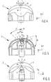
- Figure 1 is a perspective view of a part of a bicycle lamp according to the invention;
- Figure 2 is a cross-sectional view of the bicycle lamp which is shown in Figure 1;
- Figure 3 is a front view of the bicycle lamp which is shown in Figure 1;
- Figure 4 is a top plan view of the bicycle lamp which is shown in Figure 1;
- Figure 5 is a longitudinal sectional view of the bicycle lamp which is shown in Figure 1;
- Figure 6 is a bottom plan view of the bicycle lamp which is shown in Figure 1; and
- Figures 7 and 8 show embodiments of a light distributor of the bicycle lamp according to the invention which is shown in Figure 1.
-
- Parts corresponding to each other are indicated by the same numerals in the figures. In the figures, X,Y,Z-axes indicate, respectively, a horizontally rearward direction, a horizontal direction extending transversely thereto, and a vertically upward direction.
- Figures 1 - 6 show various views of a
bicycle lamp 1 according to the invention, which comprises a light-transmittingcover 2, which may for example be made of PMMA or PC. Disposed incover 2 is a light-emittingdiode 3, which is connected to a printed circuit board 4. Further connected to printed circuit board 4 is aswitch 5 disposed on a bottom side ofcover 2. Printed circuit board 4 andswitch 5 do not form part of the invention and will not be explained in detail herein, therefore. - The
cover 2 ofbicycle lamp 1 includes alight distributor 6, which comprises a V-shaped wall part 7 andparts 8 disposed on either side thereof. - As is shown most clearly in Figure 5, the V-
shaped wall part 7 comprises two facing surfaces 9 on a side facing towards light-emittingdiode 3, which surfaces intersect each other near acentral axis 10 extending parallel to the X-axis. V-shaped wall part 7 comprisessurfaces 11 on a side facing away from light-emittingdiode 3, which surfaces likewise intersect each other nearcentral axis 10. Joining V-shaped wall part 7 on either side thereof areparts 8, which are connected tospherical cover 2 on a side facing away from V-shaped wall part 7.Cover 2 has a line ofcurvature 13. The V-shaped wall part 7 of the bicycle lamp which is shown in Figures 1 - 6 is so dimensioned that the intersecting line 14 ofsurfaces 11 lies on said line ofcurvature 13. - As is clearly shown in Figure 2,
cover 2 also has acurvature 15 in a plane transversely to the Y-direction. Due to saidcurvature 15, thesurfaces 11 have a curved appearance in the front view of Figure 3. - The operation of the bicycle lamp as shown in Figures 1 - 6 will now be explained in more detail with respect to Figure 5. The light from light-emitting
diode 3 will be partially transmitted by surfaces 9, after which the light will exit the V-shaped wall part 7 viasurfaces 11. The light that partially exits fromsurfaces 11 forms a light beam extending through an angle α on either side ofcentral axis 10. Said angle α will for example be 12°. Said angle α has been selected so that a measuring point of 10° fromcentral axis 10 imposed by the law will fall within said angle. - The light reflected by a surface 9 or a
surface 11 is deflected and will exitcover 2 through an angle β. Angle β extends on either side ofcentral axis 10, for example ranging between 70° and 110°. - Light-emitting
diode 3 is further spaced from intersecting line 14 by such adistance 16 and V-shaped wall part 7 is further dimensioned such that the light from light-emittingdiode 3 can exitcover 2 at an angle of for example 45° without having passed throughlight distributor 7. This may for example be a condition which is imposed by law. - Accordingly, the light from a single light-emitting
diode 3 is distributed over a desired angle in a simple and efficient manner by the V-shaped wall part 7 of thelight distributor 6 according to the invention. - Figures 7 and 8 show a light distributor 6' and 6'', respectively, which are suitable for use as
light distributor 6 in thebicycle lamp 1 which is shown in Figures 1 - 6. - The V-shaped wall part 7' of the light distributor 6' which is shown in Figure 7 comprises parallel surfaces 9' and 11'. The
light 17 from light-emitting diode 3 will partially exit through surface 11' of V-shaped wall part 7' in alight beam 18. Thelight beam 18 extends parallel tobeam 17.Light beam 18 is staggered in Y-direction with respect tolight beam 17. Part of thelight beam 17 will be reflected aslight beam 19 by the surface 9' of V-shaped wall part 7'. - The V-shaped wall part 7'' of the light distributor 6'' which is shown in Figure 8 comprises convex surface 9'' and surfaces 11'' extending concentrically thereto. Due to the presence of said convex surfaces 9'', 1'', a
light beam 17 from light-emittingdiode 3 will form alight beam 20 upon exiting from surfaces 11'', which light beam is not fully parallel tobeam 17 and which is moreover wider than thebeam 18 of the light distributor 6' that is shown in Figure 7. Also thepart 21 oflight beam 17 that is reflected by wall part 9'' extends through a larger angle than thereflected light beam 19 of the light distributor 6' which is shown in Figure 7. - The form of
surfaces 9 and 11 of thelight distributor 6 of thebicycle lamp 1 which is shown in Figures 1 - 6 can be selected in dependence on the desired distribution of the light from light-emitting diode 3 that exits cover 2. - It is also possible for
cover 2 to join the V-shaped wall part 7 directly, wherein thewall part 7 is positioned substantially entirely before line ofcurvature 13. - It is also possible for
surfaces 9, 11 to be concave or spherical or have any other curved form. - Furthermore it is possible to interconnected the surfaces 9 disposed on either side of the central axis by means of a relatively small intermediate surface extending transversely to the central axis.
Claims (6)
- A bicycle lamp comprising a light source extending along a central axis, in particular a light-emitting diode and a cover disposed in front of the light source, which comprises a light distributor, characterized in that the light distributor comprises at least one wall part which is V-shaped both on a side facing towards the light source and on a side facing away from the light source, which V-shaped wall part comprises facing surfaces positioned on a side facing towards the light source, wherein said surfaces intersect each other near the central axis.
- A bicycle lamp according to claim 1, characterized in that said surfaces extend substantially parallel to a vertical axis extending transversely to said central axis.
- A bicycle lamp according to claim 1 or 2, characterized in that said surfaces are convex.
- A bicycle lamp according to claim 3, characterized in that a side of the V-shaped wall part facing away from the light source extends concentrically with respect to said surfaces.
- A bicycle lamp according to any one of the preceding claims, characterized in that the light distributor comprises parts disposed on either side of said V-shaped wall part, which parts are connected to the cover on sides facing away from the V-shaped wall part.
- A bicycle lamp according to any one of the preceding claims, characterized in that a line of curvature bounds the cover, wherein the V-shaped wall part touches the line of curvature near the central axis.
Applications Claiming Priority (2)
| Application Number | Priority Date | Filing Date | Title |
|---|---|---|---|
| NL1011343A NL1011343C2 (en) | 1999-02-19 | 1999-02-19 | Bicycle light. |
| NL1011343 | 1999-02-19 |
Publications (2)
| Publication Number | Publication Date |
|---|---|
| EP1029776A1 true EP1029776A1 (en) | 2000-08-23 |
| EP1029776B1 EP1029776B1 (en) | 2006-05-10 |
Family
ID=19768691
Family Applications (1)
| Application Number | Title | Priority Date | Filing Date |
|---|---|---|---|
| EP00200136A Expired - Lifetime EP1029776B1 (en) | 1999-02-19 | 2000-01-14 | Bicycle lamp |
Country Status (4)
| Country | Link |
|---|---|
| EP (1) | EP1029776B1 (en) |
| AT (1) | ATE325741T1 (en) |
| DE (1) | DE60027807T2 (en) |
| NL (1) | NL1011343C2 (en) |
Cited By (1)
| Publication number | Priority date | Publication date | Assignee | Title |
|---|---|---|---|---|
| NL1037224C2 (en) * | 2009-08-25 | 2011-02-28 | Spanninga Metaal | REAR WHEEL AND BACKLIGHT FOR A REAR WHEEL. |
Citations (4)
| Publication number | Priority date | Publication date | Assignee | Title |
|---|---|---|---|---|
| GB2184824A (en) * | 1985-12-19 | 1987-07-01 | Duracell Int | Improvements in rear lights for bicycles and other vehicles |
| CH682142A5 (en) * | 1992-04-14 | 1993-07-30 | Ver Drahtwerke Ag | |
| DE4433882A1 (en) * | 1993-09-22 | 1995-03-30 | Busch & Mueller | Rear light of a bicycle |
| EP0755850A2 (en) | 1995-07-25 | 1997-01-29 | Robert Bodenstedt | Rear light device |
-
1999
- 1999-02-19 NL NL1011343A patent/NL1011343C2/en not_active IP Right Cessation
-
2000
- 2000-01-14 DE DE60027807T patent/DE60027807T2/en not_active Expired - Lifetime
- 2000-01-14 EP EP00200136A patent/EP1029776B1/en not_active Expired - Lifetime
- 2000-01-14 AT AT00200136T patent/ATE325741T1/en not_active IP Right Cessation
Patent Citations (4)
| Publication number | Priority date | Publication date | Assignee | Title |
|---|---|---|---|---|
| GB2184824A (en) * | 1985-12-19 | 1987-07-01 | Duracell Int | Improvements in rear lights for bicycles and other vehicles |
| CH682142A5 (en) * | 1992-04-14 | 1993-07-30 | Ver Drahtwerke Ag | |
| DE4433882A1 (en) * | 1993-09-22 | 1995-03-30 | Busch & Mueller | Rear light of a bicycle |
| EP0755850A2 (en) | 1995-07-25 | 1997-01-29 | Robert Bodenstedt | Rear light device |
Cited By (1)
| Publication number | Priority date | Publication date | Assignee | Title |
|---|---|---|---|---|
| NL1037224C2 (en) * | 2009-08-25 | 2011-02-28 | Spanninga Metaal | REAR WHEEL AND BACKLIGHT FOR A REAR WHEEL. |
Also Published As
| Publication number | Publication date |
|---|---|
| NL1011343C2 (en) | 2000-08-22 |
| DE60027807D1 (en) | 2006-06-14 |
| DE60027807T2 (en) | 2006-10-19 |
| ATE325741T1 (en) | 2006-06-15 |
| EP1029776B1 (en) | 2006-05-10 |
Similar Documents
| Publication | Publication Date | Title |
|---|---|---|
| US7654721B2 (en) | LED lighting unit and vehicle lamp | |
| US6948838B2 (en) | Vehicle lamp having prismatic element | |
| US6814475B2 (en) | Led-type vehicular lamp having uniform brightness | |
| US7686497B2 (en) | Variable planar light guide module | |
| US6997587B2 (en) | Screenless elliptical illumination module producing an illumination beam with cutoff and lamp comprising such a module | |
| US11668445B2 (en) | Multi-beam vehicle light | |
| US20030169600A1 (en) | Led-type vehicular lamp having uniform brightness | |
| US20030174514A1 (en) | Vehicular lamp employing led light sources | |
| US20060234612A1 (en) | Vehicle lamp with a light guide of a multi-member configuration | |
| US20070177400A1 (en) | Vehicle lighting device | |
| EP1008801A3 (en) | A projection-type automobile light | |
| JP2009059689A (en) | Lighting module for automobile headlights | |
| JP4636678B2 (en) | Traffic lights | |
| JP2022512815A (en) | Luminous module for vehicle lighting fixtures | |
| JP2004103503A (en) | Light guide and vehicular lamp having this light guide | |
| JP5122177B2 (en) | Vehicle lighting | |
| JP2007294459A (en) | Lighting or signal transmission device with a deep appearance | |
| CN113531478B (en) | Hidden car light optical structure and car light thereof | |
| US10253940B1 (en) | Vehicle light assembly | |
| CN207661691U (en) | headlights | |
| JP6785673B2 (en) | Vehicle lighting | |
| JP5553214B2 (en) | Vehicle lighting | |
| JP2012209212A (en) | Lamp fitting for vehicle | |
| EP3540295B1 (en) | Vehicle headlamp assembly | |
| EP1029776B1 (en) | Bicycle lamp |
Legal Events
| Date | Code | Title | Description |
|---|---|---|---|
| PUAI | Public reference made under article 153(3) epc to a published international application that has entered the european phase |
Free format text: ORIGINAL CODE: 0009012 |
|
| AK | Designated contracting states |
Kind code of ref document: A1 Designated state(s): AT BE CH CY DE DK ES FI FR GB GR IE IT LI LU MC NL PT SE |
|
| AX | Request for extension of the european patent |
Free format text: AL;LT;LV;MK;RO;SI |
|
| 17P | Request for examination filed |
Effective date: 20010207 |
|
| AKX | Designation fees paid |
Free format text: AT BE CH CY DE DK ES FI FR GB GR IE IT LI LU MC NL PT SE |
|
| 17Q | First examination report despatched |
Effective date: 20050616 |
|
| GRAP | Despatch of communication of intention to grant a patent |
Free format text: ORIGINAL CODE: EPIDOSNIGR1 |
|
| GRAS | Grant fee paid |
Free format text: ORIGINAL CODE: EPIDOSNIGR3 |
|
| GRAA | (expected) grant |
Free format text: ORIGINAL CODE: 0009210 |
|
| AK | Designated contracting states |
Kind code of ref document: B1 Designated state(s): AT BE CH CY DE DK ES FI FR GB GR IE IT LI LU MC NL PT SE |
|
| PG25 | Lapsed in a contracting state [announced via postgrant information from national office to epo] |
Ref country code: AT Free format text: LAPSE BECAUSE OF FAILURE TO SUBMIT A TRANSLATION OF THE DESCRIPTION OR TO PAY THE FEE WITHIN THE PRESCRIBED TIME-LIMIT Effective date: 20060510 Ref country code: FI Free format text: LAPSE BECAUSE OF FAILURE TO SUBMIT A TRANSLATION OF THE DESCRIPTION OR TO PAY THE FEE WITHIN THE PRESCRIBED TIME-LIMIT Effective date: 20060510 Ref country code: LI Free format text: LAPSE BECAUSE OF FAILURE TO SUBMIT A TRANSLATION OF THE DESCRIPTION OR TO PAY THE FEE WITHIN THE PRESCRIBED TIME-LIMIT Effective date: 20060510 Ref country code: CH Free format text: LAPSE BECAUSE OF FAILURE TO SUBMIT A TRANSLATION OF THE DESCRIPTION OR TO PAY THE FEE WITHIN THE PRESCRIBED TIME-LIMIT Effective date: 20060510 Ref country code: IT Free format text: LAPSE BECAUSE OF FAILURE TO SUBMIT A TRANSLATION OF THE DESCRIPTION OR TO PAY THE FEE WITHIN THE PRESCRIBED TIME-LIMIT;WARNING: LAPSES OF ITALIAN PATENTS WITH EFFECTIVE DATE BEFORE 2007 MAY HAVE OCCURRED AT ANY TIME BEFORE 2007. THE CORRECT EFFECTIVE DATE MAY BE DIFFERENT FROM THE ONE RECORDED. Effective date: 20060510 |
|
| REG | Reference to a national code |
Ref country code: GB Ref legal event code: FG4D |
|
| REG | Reference to a national code |
Ref country code: CH Ref legal event code: EP |
|
| REF | Corresponds to: |
Ref document number: 60027807 Country of ref document: DE Date of ref document: 20060614 Kind code of ref document: P |
|
| REG | Reference to a national code |
Ref country code: IE Ref legal event code: FG4D |
|
| PG25 | Lapsed in a contracting state [announced via postgrant information from national office to epo] |
Ref country code: DK Free format text: LAPSE BECAUSE OF FAILURE TO SUBMIT A TRANSLATION OF THE DESCRIPTION OR TO PAY THE FEE WITHIN THE PRESCRIBED TIME-LIMIT Effective date: 20060810 Ref country code: SE Free format text: LAPSE BECAUSE OF FAILURE TO SUBMIT A TRANSLATION OF THE DESCRIPTION OR TO PAY THE FEE WITHIN THE PRESCRIBED TIME-LIMIT Effective date: 20060810 |
|
| PG25 | Lapsed in a contracting state [announced via postgrant information from national office to epo] |
Ref country code: ES Free format text: LAPSE BECAUSE OF FAILURE TO SUBMIT A TRANSLATION OF THE DESCRIPTION OR TO PAY THE FEE WITHIN THE PRESCRIBED TIME-LIMIT Effective date: 20060821 |
|
| PG25 | Lapsed in a contracting state [announced via postgrant information from national office to epo] |
Ref country code: PT Free format text: LAPSE BECAUSE OF FAILURE TO SUBMIT A TRANSLATION OF THE DESCRIPTION OR TO PAY THE FEE WITHIN THE PRESCRIBED TIME-LIMIT Effective date: 20061010 |
|
| REG | Reference to a national code |
Ref country code: CH Ref legal event code: PL |
|
| ET | Fr: translation filed | ||
| PG25 | Lapsed in a contracting state [announced via postgrant information from national office to epo] |
Ref country code: IE Free format text: LAPSE BECAUSE OF NON-PAYMENT OF DUE FEES Effective date: 20070115 |
|
| PG25 | Lapsed in a contracting state [announced via postgrant information from national office to epo] |
Ref country code: MC Free format text: LAPSE BECAUSE OF NON-PAYMENT OF DUE FEES Effective date: 20070131 |
|
| PLBE | No opposition filed within time limit |
Free format text: ORIGINAL CODE: 0009261 |
|
| STAA | Information on the status of an ep patent application or granted ep patent |
Free format text: STATUS: NO OPPOSITION FILED WITHIN TIME LIMIT |
|
| 26N | No opposition filed |
Effective date: 20070213 |
|
| GBPC | Gb: european patent ceased through non-payment of renewal fee |
Effective date: 20070114 |
|
| PG25 | Lapsed in a contracting state [announced via postgrant information from national office to epo] |
Ref country code: GB Free format text: LAPSE BECAUSE OF NON-PAYMENT OF DUE FEES Effective date: 20070114 |
|
| PG25 | Lapsed in a contracting state [announced via postgrant information from national office to epo] |
Ref country code: GR Free format text: LAPSE BECAUSE OF FAILURE TO SUBMIT A TRANSLATION OF THE DESCRIPTION OR TO PAY THE FEE WITHIN THE PRESCRIBED TIME-LIMIT Effective date: 20060811 |
|
| PG25 | Lapsed in a contracting state [announced via postgrant information from national office to epo] |
Ref country code: LU Free format text: LAPSE BECAUSE OF NON-PAYMENT OF DUE FEES Effective date: 20070114 Ref country code: CY Free format text: LAPSE BECAUSE OF FAILURE TO SUBMIT A TRANSLATION OF THE DESCRIPTION OR TO PAY THE FEE WITHIN THE PRESCRIBED TIME-LIMIT Effective date: 20060510 |
|
| REG | Reference to a national code |
Ref country code: FR Ref legal event code: PLFP Year of fee payment: 17 |
|
| REG | Reference to a national code |
Ref country code: FR Ref legal event code: PLFP Year of fee payment: 18 |
|
| REG | Reference to a national code |
Ref country code: FR Ref legal event code: PLFP Year of fee payment: 19 |
|
| PGFP | Annual fee paid to national office [announced via postgrant information from national office to epo] |
Ref country code: FR Payment date: 20190123 Year of fee payment: 20 Ref country code: NL Payment date: 20190121 Year of fee payment: 20 Ref country code: DE Payment date: 20190123 Year of fee payment: 20 |
|
| PGFP | Annual fee paid to national office [announced via postgrant information from national office to epo] |
Ref country code: BE Payment date: 20190121 Year of fee payment: 20 |
|
| REG | Reference to a national code |
Ref country code: DE Ref legal event code: R082 Ref document number: 60027807 Country of ref document: DE Representative=s name: ETL WABLAT & KOLLEGEN PATENT- UND RECHTSANWALT, DE |
|
| REG | Reference to a national code |
Ref country code: DE Ref legal event code: R071 Ref document number: 60027807 Country of ref document: DE |
|
| REG | Reference to a national code |
Ref country code: NL Ref legal event code: MK Effective date: 20200113 |
|
| REG | Reference to a national code |
Ref country code: BE Ref legal event code: MK Effective date: 20200114 |