JP2009059689A - Lighting module for headlight of automobile - Google Patents
Lighting module for headlight of automobile Download PDFInfo
- Publication number
- JP2009059689A JP2009059689A JP2008191554A JP2008191554A JP2009059689A JP 2009059689 A JP2009059689 A JP 2009059689A JP 2008191554 A JP2008191554 A JP 2008191554A JP 2008191554 A JP2008191554 A JP 2008191554A JP 2009059689 A JP2009059689 A JP 2009059689A
- Authority
- JP
- Japan
- Prior art keywords
- light emitting
- reflector
- module
- emitting diode
- light
- Prior art date
- Legal status (The legal status is an assumption and is not a legal conclusion. Google has not performed a legal analysis and makes no representation as to the accuracy of the status listed.)
- Pending
Links
Images


Classifications
-
- F—MECHANICAL ENGINEERING; LIGHTING; HEATING; WEAPONS; BLASTING
- F21—LIGHTING
- F21V—FUNCTIONAL FEATURES OR DETAILS OF LIGHTING DEVICES OR SYSTEMS THEREOF; STRUCTURAL COMBINATIONS OF LIGHTING DEVICES WITH OTHER ARTICLES, NOT OTHERWISE PROVIDED FOR
- F21V13/00—Producing particular characteristics or distribution of the light emitted by means of a combination of elements specified in two or more of main groups F21V1/00 - F21V11/00
- F21V13/02—Combinations of only two kinds of elements
- F21V13/04—Combinations of only two kinds of elements the elements being reflectors and refractors
-
- F—MECHANICAL ENGINEERING; LIGHTING; HEATING; WEAPONS; BLASTING
- F21—LIGHTING
- F21S—NON-PORTABLE LIGHTING DEVICES; SYSTEMS THEREOF; VEHICLE LIGHTING DEVICES SPECIALLY ADAPTED FOR VEHICLE EXTERIORS
- F21S41/00—Illuminating devices specially adapted for vehicle exteriors, e.g. headlamps
- F21S41/10—Illuminating devices specially adapted for vehicle exteriors, e.g. headlamps characterised by the light source
- F21S41/14—Illuminating devices specially adapted for vehicle exteriors, e.g. headlamps characterised by the light source characterised by the type of light source
- F21S41/141—Light emitting diodes [LED]
- F21S41/143—Light emitting diodes [LED] the main emission direction of the LED being parallel to the optical axis of the illuminating device
-
- F—MECHANICAL ENGINEERING; LIGHTING; HEATING; WEAPONS; BLASTING
- F21—LIGHTING
- F21S—NON-PORTABLE LIGHTING DEVICES; SYSTEMS THEREOF; VEHICLE LIGHTING DEVICES SPECIALLY ADAPTED FOR VEHICLE EXTERIORS
- F21S41/00—Illuminating devices specially adapted for vehicle exteriors, e.g. headlamps
- F21S41/10—Illuminating devices specially adapted for vehicle exteriors, e.g. headlamps characterised by the light source
- F21S41/14—Illuminating devices specially adapted for vehicle exteriors, e.g. headlamps characterised by the light source characterised by the type of light source
- F21S41/141—Light emitting diodes [LED]
- F21S41/147—Light emitting diodes [LED] the main emission direction of the LED being angled to the optical axis of the illuminating device
- F21S41/148—Light emitting diodes [LED] the main emission direction of the LED being angled to the optical axis of the illuminating device the main emission direction of the LED being perpendicular to the optical axis
-
- F—MECHANICAL ENGINEERING; LIGHTING; HEATING; WEAPONS; BLASTING
- F21—LIGHTING
- F21S—NON-PORTABLE LIGHTING DEVICES; SYSTEMS THEREOF; VEHICLE LIGHTING DEVICES SPECIALLY ADAPTED FOR VEHICLE EXTERIORS
- F21S41/00—Illuminating devices specially adapted for vehicle exteriors, e.g. headlamps
- F21S41/30—Illuminating devices specially adapted for vehicle exteriors, e.g. headlamps characterised by reflectors
- F21S41/32—Optical layout thereof
- F21S41/321—Optical layout thereof the reflector being a surface of revolution or a planar surface, e.g. truncated
-
- F—MECHANICAL ENGINEERING; LIGHTING; HEATING; WEAPONS; BLASTING
- F21—LIGHTING
- F21S—NON-PORTABLE LIGHTING DEVICES; SYSTEMS THEREOF; VEHICLE LIGHTING DEVICES SPECIALLY ADAPTED FOR VEHICLE EXTERIORS
- F21S41/00—Illuminating devices specially adapted for vehicle exteriors, e.g. headlamps
- F21S41/30—Illuminating devices specially adapted for vehicle exteriors, e.g. headlamps characterised by reflectors
- F21S41/32—Optical layout thereof
- F21S41/323—Optical layout thereof the reflector having two perpendicular cross sections having regular geometrical curves of a distinct nature
-
- F—MECHANICAL ENGINEERING; LIGHTING; HEATING; WEAPONS; BLASTING
- F21—LIGHTING
- F21S—NON-PORTABLE LIGHTING DEVICES; SYSTEMS THEREOF; VEHICLE LIGHTING DEVICES SPECIALLY ADAPTED FOR VEHICLE EXTERIORS
- F21S41/00—Illuminating devices specially adapted for vehicle exteriors, e.g. headlamps
- F21S41/30—Illuminating devices specially adapted for vehicle exteriors, e.g. headlamps characterised by reflectors
- F21S41/32—Optical layout thereof
- F21S41/36—Combinations of two or more separate reflectors
- F21S41/365—Combinations of two or more separate reflectors successively reflecting the light
-
- F—MECHANICAL ENGINEERING; LIGHTING; HEATING; WEAPONS; BLASTING
- F21—LIGHTING
- F21Y—INDEXING SCHEME ASSOCIATED WITH SUBCLASSES F21K, F21L, F21S and F21V, RELATING TO THE FORM OR THE KIND OF THE LIGHT SOURCES OR OF THE COLOUR OF THE LIGHT EMITTED
- F21Y2115/00—Light-generating elements of semiconductor light sources
- F21Y2115/10—Light-emitting diodes [LED]
Abstract
Description
本発明は、カットオフビーム、特にロービームを発生するための自動車のヘッドライト用照明モジュールに関する。 The present invention relates to an illumination module for a headlight of an automobile for generating a cut-off beam, in particular a low beam.
例えば、特許文献1により、
少なくとも1つの光源と、
複合表面タイプの反射器とを備え、前記光源は、光軸、またはその光軸に近い焦点に位置し、前記反射器は、前方に向けてカットオフビームを発生するようになっており、
楕円の弧の2つの焦点の間に位置する垂直の母線を有する円筒形レンズとを更に備え、1つの光軸を有するモジュールは、公知となっている。
For example, according to
At least one light source;
A reflector of a composite surface type, the light source is located at an optical axis or a focal point close to the optical axis, and the reflector generates a cut-off beam toward the front,
Modules having one optical axis are further known, further comprising a cylindrical lens having a vertical generatrix located between the two focal points of an elliptical arc.
前記特許文献1では、かかるモジュールと補助反射器とを組み合わせているが、このような装置は、垂直方向に比較的かさばるので、徐々に曲がる照明光(PBL)を発生するヘッドライトを得るために、モジュールを垂直方向に重ねることはほとんど不可能である。そのため、モジュールを水平方向に並置しなければならず、幅の広い組立体となっている。
In
本発明の目的は、垂直方向に比較的かさばらない照明モジュールを提供すること、特に、高さ方向に数個のモジュールを積み重ねることができるようにすることである。 The object of the present invention is to provide a lighting module which is relatively bulky in the vertical direction, in particular to allow several modules to be stacked in the height direction.
本発明の別の目的は、同じ光束を発生するのにエネルギー消費量が少ない、高効率の照明モジュールを提供することにある。仕様条件を満たすために、モジュールが発生する光ビームを良好に拡散することも望ましい。
本発明によれば、照明モジュールは、
少なくとも1つの光源と、
複合表面タイプの反射器とを備え、前記光源は、光軸、またはその光軸に近い焦点に位置しており、水平平面を通る前記反射器の断面は、前記光源が位置する焦点と合流するか、またはこの焦点の近くにある第1焦点、および前記モジュールの光軸上で前方に位置する第2焦点を有する楕円の弧内に実質的にあり、前記反射器は、前方に向けてカットオフビームを発生し、
楕円の前記弧の2つの焦点の間に位置する実質的に垂直な母線を有する円筒形レンズとを更に備え、1つの光軸を有し、カットオフビーム、特にロービームを発生するための自動車のヘッドライト用照明モジュールであって、
前記光源は、発光ダイオードからの光ビームが前記反射器の幾何学的軸線に実質的に直交する平均方向を有するように配置された、少なくとも1つの発光ダイオードを備え、
前記反射器は、発光ビーム側において、前記発光ダイオードの背面に位置しており、反射器の表面積の計算は、前記発光ダイオードの保護光学的部分を考慮して行われるようになっている。
According to the invention, the lighting module comprises:
At least one light source;
A reflector of a composite surface type, wherein the light source is located at an optical axis or a focal point close to the optical axis, and a cross section of the reflector passing through a horizontal plane meets a focal point where the light source is located Or substantially within an elliptical arc having a first focus near this focus and a second focus located forward on the optical axis of the module, the reflector being cut forward Generate off-beam,
A cylindrical lens having a substantially vertical generatrix located between the two focal points of the arc of the ellipse, and having a single optical axis and an automobile for generating a cut-off beam, in particular a low beam A lighting module for headlights,
The light source comprises at least one light emitting diode arranged such that a light beam from the light emitting diode has an average direction substantially perpendicular to the geometric axis of the reflector;
The reflector is positioned on the back side of the light emitting diode on the emission beam side, and the calculation of the surface area of the reflector is performed in consideration of the protective optical part of the light emitting diode.
上記したところにより、選択された光源から発生される光線を保護することに起因して生じる偏差(保護ドームを有するLEDの球形キャップ)、またはオフセット(ブレードが保護するLEDの平面状ブレード)を適当に考慮して、反射器の表面積を計算することが理解できると思う。 As described above, the deviation (spherical cap of LED with protective dome) or offset (planar blade of LED that the blade protects) caused by protecting the light emitted from the selected light source is appropriate. I think you can understand how to calculate the surface area of the reflector.
上記水平方向の平面は、発光ダイオードの出口面に合流するか、またはこれに極めて接近していることが好ましい。 Preferably, the horizontal plane meets or is very close to the exit face of the light emitting diode.
レンズは、ほぼ発散タイプであることが好ましいが、レンズにおける1つまたは複数の領域を、発散タイプとすることはできない。 The lens is preferably approximately divergent, but one or more regions in the lens cannot be divergent.
「複合表面」なる用語は、カバーまたはディッシュが存在しない場合に、画像を整合することにより、カットオフを発生するように構成された表面を意味する。この用語は、当技術分野においては、「フリー表面」とも呼ばれている。 The term “composite surface” refers to a surface that is configured to generate a cut-off by aligning images in the absence of a cover or dish. This term is also referred to in the art as “free surface”.
前記発光ダイオードは、前記反射器の反対側に位置するヒートシンクを有することが好ましい。 Preferably, the light emitting diode has a heat sink located on the opposite side of the reflector.
このような組立体により、シャープなカットオフラインを有し、出力が大きく、エネルギー消費量が少ない、広い発散ビームを得ることが可能となる。 Such an assembly makes it possible to obtain a wide divergent beam having a sharp cut-off line, high output and low energy consumption.
前記発光ダイオードは、実質的に垂直平均方向に光ビームを、下向きに発生するよう、その背面が水平平面内にあるように配置されており、前記発光ダイオードの前記ヒートシンクは、前記発光ダイオードの上方に位置し、一方、前記反射器は、前記ダイオードの前記背面の前記水平平面より下方に位置していることができる。 The light emitting diode is disposed so that a back surface thereof is in a horizontal plane so as to generate a light beam in a substantially vertical average direction downward, and the heat sink of the light emitting diode is located above the light emitting diode. While the reflector may be located below the horizontal plane of the back of the diode.
上記とは異なり、前記発光ダイオードは、実質的に垂直平均方向に光ビームを上向きに発生するよう、その背面が水平平面内にあるように配置されており、前記発光ダイオードの前記ヒートシンクは、前記発光ダイオードの下方に位置し、一方、前記反射器は、前記ダイオードの前記背面の前記水平平面より上方に位置していることもある。 Unlike the above, the light emitting diode is disposed so that its back surface is in a horizontal plane so as to generate a light beam upward in a substantially vertical average direction, and the heat sink of the light emitting diode is The reflector may be located below the light emitting diode, while the reflector is located above the horizontal plane on the back of the diode.
前記発光ダイオードは、実質的に水平の平均的方向を有する光ビームを発生するよう、その背面が、実質的に垂直平面にあるように配置されており、前記発光ダイオードのヒートシンクは、前記発光ダイオードの後方に位置している。一方、前記反射器は、前記発光ダイオードの前方に位置するとともに、下方を向いており、光ビームを前記レンズに向けて戻すよう、前記反射器の下方には、リターンミラーが配置されている。 The light emitting diode is disposed such that a back surface thereof is in a substantially vertical plane so as to generate a light beam having a substantially horizontal average direction, and the heat sink of the light emitting diode is the light emitting diode. Located behind. On the other hand, the reflector is located in front of the light emitting diode and is directed downward, and a return mirror is disposed below the reflector so as to return the light beam toward the lens.
上記とは異なり、前記発光ダイオードは、実質的に水平平均方向を有する光ビームを発生するよう、その背面が実質的に垂直平面にあるように配置されている。前記発光ダイオードのヒートシンクは、前記発光ダイオードの後方に位置しており、一方、前記反射器は、前記発光ダイオードの前方に位置すると共に上方に向いている。光ビームを前記レンズに向けて戻すよう、前記反射器の上方には、リターンミラーが配置されている。 Unlike the above, the light emitting diodes are arranged so that their backs are in a substantially vertical plane so as to generate a light beam having a substantially horizontal average direction. The heat sink of the light emitting diode is located behind the light emitting diode, while the reflector is located in front of the light emitting diode and facing upward. A return mirror is disposed above the reflector so as to return the light beam toward the lens.
前記リターンミラーは、平面状とするのが良く、水平平面に対して、約45°傾斜させられる。ダイオードの平面が厳密に垂直ではない場合には、この角度を変えることができる。 The return mirror is preferably flat and is inclined about 45 ° with respect to a horizontal plane. This angle can be varied if the diode plane is not exactly vertical.
本発明は、上記モジュールを少なくとも1つ備えるヘッドライトにも関する。 The present invention also relates to a headlight comprising at least one of the above modules.
このヘッドライトは、背面が、水平平面に位置するよう配置された、発光ダイオードを有する数個のモジュールを含むのがよく、前記モジュールは、発光ダイオードの背面が同一水平平面に位置するよう並置される。 This headlight may include several modules with light emitting diodes arranged so that the back side is located in a horizontal plane, said modules being juxtaposed so that the back side of the light emitting diodes is located in the same horizontal plane. The
このヘッドライトは、数個のモジュールを含むことができ、この場合、このモジュールは、発光ダイオードの背面が同一平面に位置するように、並置または積み重ねられる。 The headlight can include several modules, in which case the modules are juxtaposed or stacked so that the backside of the light emitting diodes are coplanar.
このヘッドライトは、背面が、1つの同じ平面に位置するよう配置された、発光ダイオードを有する数個のモジュールを含むことができ、前記モジュールは、発光ダイオードの背面が同一垂直平面にあり、同一のプリント回路基板の位置するよう積み重ねられている。 The headlight can include several modules with light emitting diodes arranged so that the back side is located in one and the same plane, said modules having the back side of the light emitting diodes in the same vertical plane and the same The printed circuit boards are stacked to be positioned.
一実施例に係わる前記モジュールは、積み重ねられており、底部から頂部までの水平投影面において、回転角方向にオフセットしたビームを有し、プログレッシブベンディング照明(英語のprogressive bending lightの略であるPBL)が得られるように、車輪の方向転換に従って、逐次オンに切り換えられる。 The module according to one embodiment is stacked, has a beam offset in the rotational angle direction in a horizontal projection plane from the bottom to the top, and is a progressive bending light (PBL for English progressive bending light). Is sequentially switched on as the wheels change direction.
このヘッドライトは、ビームが回転角方向にオフセットしている3つまたは4つの積み重ねられたモジュールを備えている。 This headlight comprises three or four stacked modules in which the beam is offset in the direction of the rotation angle.
前記リターンミラーは、前記底部モジュールの反射器の上方または下方に配置されることが好ましく、また、前記モジュールの反射器と単一の部品を形成することが好ましい。 The return mirror is preferably arranged above or below the reflector of the bottom module and preferably forms a single part with the reflector of the module.
本発明は、上記記載の手段とは別に、以下、添付図面を参照して説明する実施例において明瞭に示されている所定の数の別の手段を備えている。 In addition to the above-described means, the present invention comprises a predetermined number of other means clearly shown in the embodiments described below with reference to the accompanying drawings.
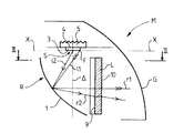
図1および図2には、カットオフビーム、特にロービームを発生するようになっている自動車用ヘッドライトのための照明モジュールMが示されている。このモジュールは、水平方向の光軸X−Xを有し、少なくとも1つの光源Sと、複合表面タイプの反射器Rとを備えている。反射器Rの幾何学的な軸線は、光軸X−Xと合流している。 1 and 2 show an illumination module M for an automotive headlight adapted to generate a cut-off beam, in particular a low beam. This module has a horizontal optical axis XX and comprises at least one light source S and a composite surface type reflector R. The geometric axis of the reflector R meets the optical axis XX.
光軸X−Xに平行な垂直平面を通過する反射器Rの断面、例えば1は、凹部が前方に向いた、すなわち、図1の右側を向く放物面の弧内に実質的にある。モジュールの光軸X−Xを通過する水平平面内に焦点が位置し、弧1は、光軸X−Xを通過する垂直平面が通る反射器Rの断面に対応し、この軸線に焦点Fが位置している。
The cross section of the reflector R, for example 1 passing through a vertical plane parallel to the optical axis XX, is substantially within a parabolic arc with the recess pointing forward, i.e. to the right in FIG. The focal point is located in the horizontal plane passing through the optical axis XX of the module, and the
光源Sは、焦点Fに位置するか、またはその近くに位置している。光軸を通る水平平面が通過する反射器Rの断面は、焦点Fに合流するか、またはこの焦点Fに隣接する第1焦点F1と、モジュールの光軸の前方に位置する第2焦点F2を有する楕円2(図2)の弧内に実質的に位置している。 The light source S is located at or near the focal point F. The cross section of the reflector R through which the horizontal plane passing through the optical axis passes has a first focal point F1 adjacent to or adjacent to the focal point F and a second focal point F2 located in front of the optical axis of the module. It is substantially located within the arc of the ellipse 2 (FIG. 2) it has.
複合表面タイプの反射器Rは、カットオフを有するビームを、前方に向けて発生する。このカットオフは、平坦なライン、特にフォグ機能のためには、水平の平らなラインに対応している。カットオフは、特にロータイプのビーム(このタイプのビームは、欧州の交通規則によれば、15°傾斜した水平方向の平坦なセグメントを含む破線状のカットオフを有する)の斜め部分の形成に寄与する、平らで、かつ斜めのラインにも、対応できる。 The composite surface type reflector R generates a beam having a cutoff toward the front. This cutoff corresponds to a flat line, especially a horizontal flat line for the fog function. The cut-off is in particular the formation of an oblique part of a low-type beam (this type of beam has a dashed cut-off comprising a horizontal flat segment inclined 15 ° according to European traffic regulations). Contributes to flat and diagonal lines that contribute.
楕円2の弧の焦点F1およびF2を通過し、光軸と直交する2つの平面の間には、垂直の母線を有する円筒形レンズLが配置されている。このレンズは、全体として発散レンズの形状となっており、発散レンズの少なくとも一部の領域を、発散タイプとすることはできない。
A cylindrical lens L having a vertical generatrix is disposed between two planes passing through the focal points F1 and F2 of the arc of the
本発明によれば、LEDなる略語で示される,少なくとも発光ダイオード3により、光源Sが形成される。LED3のエミッタは、1〜5mmの辺を有する四角形または正方形の平坦なタイプであることが好ましい。反射器Rの焦点距離は、このようなエミッタでは、約5mmである。LED3は、その光ビームの平均方向Δが、反射器Rの幾何学的軸線に対して、実質的に垂直方向および/または直角方向となるように、下方を照明するようになっている。この反射器Rは、LEDの背面4の平面に対して、LED3が発光する光ビームの側に位置している。反射器Rの表面積を計算する際には、LED3の保護レンズを考慮に入れる。
According to the present invention, the light source S is formed by at least the
図1および図2に示すように、LED3の前方エッジは、焦点Fに位置し、LEDは、焦点Fから後方に向いて延びている。集光反射器Rは、この反射器の各ポイントにおいて、LED3の前方エッジから発するような光線、例えばI1が、光線、例えばR1として水平方向に反射されるか、または水平線に対して、15°で上昇する斜めの平坦なカットオフラインを構成するように定められている。
As shown in FIGS. 1 and 2, the front edge of the
前方エッジの後方に位置するLED3上のポイントから発せられる光線、例えばI2は、水平線より下方に降下する光線、例えばR2に沿って反射される。従って、このような構造により、照明されるゾーンは、水平のカットオフ、または水平線から上昇する傾斜したカットオフよりも下に位置する。
Rays emanating from a point on
照明される部分が、カットオフラインよりも上方に位置し、このカットオフラインよりも下方に暗い部分があるビームを得たい場合、LED3の後方エッジが焦点Fを通過し、この焦点の前方にLED3が位置するようにLED3を配置する。
If the part to be illuminated is located above the cut-off line and it is desired to obtain a beam with a dark part below this cut-off line, the rear edge of
反射器Rと反対側において、このLEDの背面に対して、LED3が放出する熱を排出するためのヒートシンク5が配置されている。
On the side opposite to the reflector R, a
このモジュール全体は、ハウジング内に配置されており、このハウジングは、前方が透明レンズGによって閉じられている。 The entire module is arranged in a housing, and the front of the housing is closed by a transparent lens G.
図1および図2に示す実施例においては、LED3の背面4は水平となり、ヒートシンク5が上方向を向くように、LED3が配置されている。この反射器は、背面4の水平平面よりも下方に位置している。
In the embodiment shown in FIGS. 1 and 2, the
集光反射器Rと焦点F2との間の任意のポイントに、基本的には発散性の円筒形レンズLを配置でき、このレンズによって、ビーム内の光の水平方向の分布を調節することが可能となる。 A divergent cylindrical lens L can be placed at any point between the collector reflector R and the focal point F2, and this lens can adjust the horizontal distribution of light in the beam. It becomes possible.
効率を改善するために、図3〜図5のローカットオフを有する変形実施例では、レンズLaは、ビームを曲げる前に反射器を超えて上に移動し、かつ図1および図2の場合、レンズLは反射器を超えて下方に移動しなければならない。その理由は、ビームが発散すれば、かえってビームは反射器から離間するからである。 To improve efficiency, in the alternative embodiment with the low cutoff of FIGS. 3-5, the lens La moves over the reflector before bending the beam, and in the case of FIGS. 1 and 2, The lens L must move down past the reflector. The reason for this is that if the beam diverges, it will be separated from the reflector.
他方、レンズL、LaがF2に近くなればなるほど、このレンズは、潜在的により狭くなる(幅は図1の平面に垂直な方向の寸法に対応する)。その理由は、平面図におけるビームは、F2に向かって収束するが、その効果は光源のサイズに起因する発散のため、選択する光源、およびその向きに従って、一部または全体が相殺されるからである。しかしながら、レンズを反射器Rに接近させ、水平方向の分布を良好に制御することが望ましい。 On the other hand, the closer the lens L, La is to F2, the narrower this lens will be (the width corresponds to the dimension in the direction perpendicular to the plane of FIG. 1). The reason is that the beam in the plan view converges towards F2, but the effect is divergence due to the size of the light source, so that it is partially or wholly offset depending on the selected light source and its orientation. is there. However, it is desirable to bring the lens closer to the reflector R and to better control the horizontal distribution.
図1および図2のモジュールMにより、効率を高くできる。これにより、低い電気エネルギー消費量で満足できる光束を得ることが可能となるが、第1にヒートシンク5の配置により、第2に同じ平面にLEDが位置せず、これによって、LEDを単一のプリント回路基板に設置することが阻害されると共に、電気的な接続が複雑となるという理由から、モジュール自体を垂直方向に積み重ねることはできない。しかし、モジュールを水平方向に並置し、同じ水平平面にLEDの背面が位置するよう、単一の水平のプリント回路基板に実装することが可能である。
Efficiency can be increased by the module M of FIGS. This makes it possible to obtain a satisfactory luminous flux with low electric energy consumption, but firstly, due to the arrangement of the
図3に示すように、垂直方向の積み重ねを容易に可能にするため、本発明に係わるモジュールMaは、少なくとも1つのLED3aを備え、実質的に水平方向の平均方向Δaを有する光ビームを前方に向けて発生するよう、このLEDの背面4aは、垂直平面6に位置しているのが好ましい。
As shown in FIG. 3, in order to facilitate vertical stacking, the module Ma according to the present invention comprises at least one
LEDのヒートシンク5aは、LEDの後方に位置しているが、反射器Raは、LEDの凹部が下に向いた状態で、LEDの前方に位置している。反射器Raの幾何学的軸線(図3では示されていない)は、垂直となっている。LEDのビームの平均方向Δaは、水平方向であり、よって反射器Raの幾何学的軸線に対して直角となっている。垂直母線を有するレンズLaにビームを向けるよう、反射器RaとRa1,Ra2との間に、平坦なリターンミラー7が配置されている。このミラー7は、水平平面に対して、好ましくは45°傾斜している。
The
図3に示す数個のモジュール、例えば3つの同様なモジュールMa、Ma1、Ma2を、垂直方向に積み重ねることができる。ここで、LED3a、3a1、3a2の背面4a、4a1、4a2は、1つの同一の垂直平面6に位置し、同一の垂直のプリント回路基板8に接続できる。ヒートシンク5a、5a1、5a2は、それぞれ、各LEDの後方に配置されているが、変形例では、複数のヒートシンクを、単一の共通ヒートシンクにまとめることも可能である。
Several modules shown in FIG. 3, for example three similar modules Ma, Ma1, Ma2, can be stacked vertically. Here, the rear surfaces 4a, 4a1, 4a2 of the
リターンミラー7によって生じるビームを回転させることにより、LED3aの頂部エッジが、反射器Raの焦点Faに実質的に位置するように、LED3aは配置されている。焦点より下方に位置するLED3aの領域から生じるI3のような光線は、Raにより下方に反射され、外側に向かって戻され、次に、r3のような光線に沿って、ミラー7により下方に反射される。レンズLaは、3つのモジュールに共通し、この目的のために十分な高さを有する。
The
例えば欧州特許第EP-A-1,500,553号に開示されているPBL機能(プログレッシブベンディング光、すなわち英語で「progressive bending light」)を満たすために、モジュールを、次々にスイッチオンすることにより、例えば底部モジュールから、頂部モジュールまで逐次オンにスイッチングすることにより、光ビームがカーブの内側に向くように重ねられたモジュールMa、Ma1、Ma2のビームの平均方向は、垂直軸線を中心として回転角方向にオフセットされる。 For example, the bottom module is switched on one after another in order to fulfill the PBL function (progressive bending light, ie “progressive bending light” in English) as disclosed in EP-A-1,500,553, for example. By switching on sequentially from the top module to the top module, the average direction of the beams of the modules Ma, Ma1 and Ma2 stacked so that the light beam faces the inside of the curve is offset in the rotation angle direction about the vertical axis The
下方に位置するモジュールの反射器Ra1、Ra2の背部には、モジュールの平らなリターンミラー7が固定されており、このミラーは、この反射器と一体的な部品を形成している。レンズLaの入口面9は、種々のモジュールの間の移行領域にて段部を有することができるが、一方、このレンズの出口面10は、段部を有しないスムーズな面となっている。
A
本発明によるモジュール、または複数のモジュールのスタックから成るヘッドライトは、次の特徴事項を有する。
−レンズは、各モジュールに対し、垂直軸線を有する円筒形となっており、レンズは垂直方向の度を有しておらず、そのため、レンズの上流側でビームのカットオフを完全に実行しなければならない。これは、反射器R、Ra、Ra1、Ra2によってカットオフが生じるケースである。
−モジュールまたはヘッドライトは、ベンダーを有するモジュールと同じような良好な効率を有し、密な光、すなわち光束はPBL機能に対して大きくなっている。
−図3〜図5に示す変形例におけるLEDは、同じ垂直平面に位置し、ヒートシンクに対して直立しているので、これにより、製造プロセスは簡単となり、コストを削減できる。
A headlight comprising a module according to the invention or a stack of modules has the following characteristics.
-The lens has a cylindrical shape with a vertical axis for each module, and the lens does not have a vertical degree, so the beam cut-off must be performed completely upstream of the lens. I must. This is the case where a cut-off occurs due to the reflectors R, Ra, Ra1, Ra2.
The module or headlight has a good efficiency similar to the module with the vendor, the dense light, i.e. the luminous flux, is larger for the PBL function.
The LEDs in the variants shown in FIGS. 3 to 5 are located in the same vertical plane and stand upright with respect to the heat sink, which simplifies the manufacturing process and reduces costs.
平らなリターンミラーを必要とする図3〜図5のベンディングバージョンにおける反射器の位置を検討すると、対応するモジュールMa、Ma1、Ma2は、平坦なミラーにより、曲げる前に、下方のカットオフを発生しなければならず、すべての光は、前の図の基準フレーム内で水平線よりも上に位置していなければならないことに留意する必要がある。 Considering the position of the reflector in the bending version of FIGS. 3-5, which requires a flat return mirror, the corresponding modules Ma, Ma1, Ma2 generate a lower cut-off before bending due to the flat mirror Note that all light must be above the horizon in the reference frame of the previous figure.
ロケーション上の理由から、すべての反射器を含む部分が、頂部端部よりも上ではなく、レンズの底部より下方に投影させると判断した場合、非曲げ基本システムは、使用する基準フレーム内でロータイプのカットオフを発生しなければならず、この場合、すべての光は、水平のカットオフよりも下方に位置しなければならない。この場合、集光ミラーRよりも上にLEDが位置し、集光ミラー自体が、リターンミラー7よりも下方に位置し、図に示されている構造と比較して、反転された構造が得られる。
If, for location reasons, it is determined that the part containing all the reflectors is projected below the bottom of the lens rather than above the top edge, the unbent basic system will A type of cut-off must be generated, in which case all the light must be located below the horizontal cut-off. In this case, the LED is located above the condenser mirror R, the condenser mirror itself is located below the
複合表面タイプの反射器R、Ra、Ra1、Ra2は、LED3に適合している。その理由は、必要とする焦点距離(1〜5mmの側面を有する発光器では約5mm)を鑑みれば、LEDの保護レンズを考慮しなければならないからである。 Composite surface type reflectors R, Ra, Ra1, Ra2 are adapted to LED3. The reason is that in view of the required focal length (about 5 mm for a light emitter with 1-5 mm side), a protective lens for the LED must be considered.
反射器の表面積の計算。
第1のケース:焦点を通過する垂直平面が通るLED(発光器+保護レンズ)の断面は、発光器の断面を示すセグメントの焦点の後方の長さ、またはハイカットオフではなく、ロータイプのカットオフを得たい場合には、焦点の前方の長さを除き、当該カッティング平面からは独立する。
Calculation of reflector surface area.
First case: The cross section of the LED (light emitter + protective lens) through the vertical plane passing through the focus is the length behind the focus of the segment showing the cross section of the light emitter, or the low type cut, not the high cut off If it is desired to get off, it is independent of the cutting plane except for the length in front of the focal point.
このケースは、平行な面を有するブレード、またはプレートタイプの保護レンズに対応している。 This case corresponds to a blade having parallel surfaces or a plate type protective lens.
これらの条件下では、所定の平坦なパラメータ曲線(水平平面に含まれる直線および曲線)に対し、検討するポイントPで接する直線を検討する場合、およびこの直線に対して垂直で、かつ(発光器上で注意深く選択されたポイントである)焦点Fを通過する平面を検討する場合、仮想的反射器表面に対するこの垂直平面内の2Dの光学的構造を有効に円筒形とすることができる。この円筒形の断面は、構造の結果によるものであり、かつ、その方向に、上記直線(この直線は円筒形の母線のうちの1つである)がある。その理由は、この構造の平面における焦点から発せられるすべての光線は、その内部に含まれたままである(上記断面での性質の結果である)からであり、この構造は、円筒形の任意のポイントにおける円筒形の方向への投影が有効であるからである。 Under these conditions, when considering a straight line tangent at a point P to be examined with respect to a predetermined flat parameter curve (straight line and curve included in the horizontal plane), and perpendicular to this straight line and (light emitting device) When considering a plane through the focal point F (which is a carefully selected point above), the 2D optical structure in this vertical plane relative to the virtual reflector surface can be effectively cylindrical. This cylindrical cross section is the result of the structure and in that direction is the straight line (this straight line is one of the cylindrical bus bars). The reason is that all rays emanating from the focal point in the plane of this structure remain contained within it (which is a result of the properties in the cross section above), and this structure can be any cylindrical shape This is because the projection in the cylindrical direction at the point is effective.
この第1のケースは、次のようなLEDの2つの公知のファミリーに対応している。 This first case corresponds to two known families of LEDs as follows.
1a/発光器が平らな出口面において透明材料、特に樹脂の保護層内に封入されているファミリー(図6)。 1a / family in which the light emitter is encapsulated in a protective layer of transparent material, in particular resin, at the flat exit face (FIG. 6).
1b/発光器が発光器とブレードとの間の空気層により、平らで透明なブレード、特にガラスブレードによって保護されているだけのファミリー。 1b / family in which the light emitter is only protected by a flat and transparent blade, in particular a glass blade, by the air layer between the light emitter and the blade.
x(発光器の側面の1つに自ら平行な基準フレームの軸)に平行な方向に関し、上記LEDの2つのファミリー(1a、1b)に対する断面、ローカットオフの場合には曲げて、集光した後のデッドゾーンを計算する方法を下記に示す。この場合、焦点は構成の際の反射器の部分までのxに沿った反対側での、光軸に沿った最も前方に位置する発光器のコーナーであり、反対の側面は、対称性によって構成できるが、必ずしも同じパラメータを有するわけではなく、すなわち、z=0に沿った同じ断面を有するわけではない。ここに開示する計算方法は、差分方程式である基礎となる方程式の1つの基本的な数値解法である。 x (cross-section for the two families of LEDs (1a, 1b) above in the direction parallel to x (the axis of the reference frame parallel to one of the side surfaces of the light emitter); The method for calculating the later dead zone is shown below. In this case, the focal point is the corner of the most forward emitter along the optical axis on the opposite side along x to the part of the reflector in construction, the opposite side being configured by symmetry Although not necessarily having the same parameters, i.e. not having the same cross section along z = 0. The calculation method disclosed here is one basic numerical solution of an underlying equation that is a difference equation.
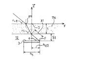
図6を参照すると、次のことが分かる。
hs=方向Yでの発光器の寸法
δ=発光器より上の透明層の厚み
δ1=(図7に示されるような)発光器と保護ブレードとの間の空気の厚さ
e=層の出口表面を有する焦点から生じた光線の角度
ye=光線の出口ポイントのyに沿った座標
r=層の出口表面により空気内で屈折される光線の角度
M0=反射器の表面における既知のポイント
ベクトル(数1)は、反射器の表面に対するM0での垂線である。

ベクトル(数2)は、反射器の表面に対するMにおける垂線である。
λ=Mと垂線の出口ポイントとの間のセグメントの長さ
Referring to FIG. 6, the following can be understood.
h s = dimension of the emitter in direction Y δ = thickness of the transparent layer above the emitter δ1 = the thickness of the air between the emitter and the protective blade (as shown in FIG. 7) e = of the layer The angle of the ray originating from the focal point with the exit surface y e = coordinate along y of the exit point of the ray r = the angle of the ray refracted in air by the exit surface of the layer M 0 = known point on the surface of the reflector The vector (Equation 1) is a perpendicular at M 0 to the reflector surface.
ベクトル(数3)は、入射光線と水平線との間の角度の二等分線に従って配向される。
反射器の断面の計算
1a−透明保護プレート11または層内に埋め込まれた、封入されたLEDのケース(図6のダイヤグラム):
δ1=空気層12の厚さであり、
t=透明プレートまたは層1aの厚さである。
δ1 = the thickness of the
t = the thickness of the transparent plate or layer 1a.
ここで、eminは、ye=−f(eを単位とする方程式)となるような値であり、この場合、fは図2に示されるように、Fと光軸に沿って測定されたミラーの底部との間の距離である。 Here, e min is a value such that (equation in units of e) y e = -f, in this case, f is as shown in FIG. 2, measured along the F and the optical axis The distance between the bottom of the mirror.
この計算式の残りの部分は、前のケースと同様である。 The rest of this calculation is the same as in the previous case.
次に、パラメータ曲線上の検討する任意のポイントPでの適当な正接円筒体を計算し、完全な表面(この表面は円筒体の無限の内側エンベロープ、すなわち光源側のエンベロープである)を構築することが可能である。求めるエンベロープに属する円筒体の各々の断面、すなわち、Pにおける反射をF1から生じる光線に並列な、含まれる垂直平面Pを通る断面を計算する。Pを通過し、Pで全体が楕円のパラメータ曲線に対する垂線を含む垂直平面へのFおよびエミッタの投影後、上記のように円筒体の断面を計算する。 Next, calculate an appropriate tangent cylinder at any point P to consider on the parameter curve, and build a complete surface (this surface is the infinite inner envelope of the cylinder, ie the light source side envelope). It is possible. Compute the cross-section of each cylindrical body belonging to the desired envelope, i.e., the cross-section through the included vertical plane P parallel to the rays resulting from reflection at P. After projecting F and the emitter onto a vertical plane that passes through P and contains a normal to a parameter curve that is entirely elliptical at P, calculate the cross-section of the cylinder as described above.
焦点FおよびF2の楕円の弧は、パラメータ曲線に対してとることが好ましい。 The elliptical arc of the focal points F and F2 is preferably taken for the parameter curve.
例えばFとF1とは、合流されるか、または実質的に合流されるが、このことは、1つの例にすぎず、FとF1とは別個でもよい。 For example, F and F1 are merged or substantially merged, but this is only one example, and F and F1 may be separate.
次に計算により、測定スクリーン上の等照度曲線の形状、およびビームの全幅を制御できるようにする画像の水平方向の偏差パラメータに従って、出口レンズを構成する。より詳細については、欧州特許第EP1243846号に記載の構成方法を参考とすることができる。 The exit lens is then constructed according to the shape of the iso-illuminance curve on the measurement screen and the horizontal deviation parameter of the image allowing the total beam width to be controlled by calculation. For more details, the construction method described in European Patent No. EP1243846 can be referred to.
第2のケース−このケースは、特に球形ドームによってLEDが保護されるケースである。保護レンズへの垂線は、構成平面には含まれない(従ってこの光線は、切断平面内に留まらない)ので、2D構造には意味がない。 Second case-this is the case where the LED is protected in particular by a spherical dome. The normal to the protective lens is not included in the construction plane (thus this ray does not stay in the cutting plane), so there is no meaning in the 2D structure.
使用する原理は、エミッタのコーナー(上記のようにF)から、中心の球形波F2に生じる球形波を変換することから成っている。この計算は、明らかに保護ドーム(このドームは焦点を中心としない)に起因する偏差を考慮する。 The principle used consists of transforming the spherical wave generated in the central spherical wave F2 from the corner of the emitter (F as described above). This calculation clearly accounts for deviations due to the protective dome (which is not centered on the focal point).
この計算手順は、比較的簡単であり、その理由は、平面図において、F2に向かって収束するビームの選択とは関係なく、ローカットオフを有するビームを作成したいということによるものである。 This calculation procedure is relatively simple because it is desired to create a beam with a low cutoff in the plan view regardless of the selection of the beam that converges towards F2.
本発明によって得られる利点として、垂直レンズL、Laがスムーズな出口表面を有することを挙げることができる。更に、3つの光学的部品だけを組み立てればよい。すなわち、
プリント回路基板および/またはヒートシンクに固定されたすべてのLEDと、
ヒートシンクおよびレンズに固定するためのラグ(図示せず)を含む反射器と、
レンズとを組み立てるだけでよい。
An advantage obtained by the present invention is that the vertical lenses L and La have a smooth exit surface. Furthermore, only three optical components need be assembled. That is,
All LEDs fixed to the printed circuit board and / or heat sink;
A reflector including a heat sink and a lug (not shown) for securing to the lens;
Just assemble the lens.
S 光源
R、Ra、Ra1、Ra2 反射器
F1 第1焦点
F2 第2位焦点
L、La 円筒形レンズ
3、3a、3a1、3a2 発光ダイオード
4、4a、4a1、4a2 背面
5、5a、5a1、5a2 ヒートシンク
7 リターンミラー
9 入口面
10 出口面
S Light source R, Ra, Ra1, Ra2 Reflector F1 First focus F2 Second focus L,
Claims (13)
複合表面タイプの反射器(R、Ra、Ra1、Ra2)とを備え、
前記光源は、光軸、またはその光軸に近い焦点(F)に位置しており、水平平面を通る前記反射器の断面は、前記光源が位置する焦点(F)と合流するか、またはこの焦点の近くにある第1焦点(F1)、および前記モジュールの光軸上で前方に位置する第2焦点(F2)を有する楕円の弧内に実質的にあり、前記反射器は、前方に向けてカットオフビームを発生するようになっており、更に
楕円の前記弧の2つの焦点(F1、F2)の間に位置する実質的に垂直な母線を有する円筒形レンズ(L、La)を備え、1つの光軸を有し、カットオフビーム、特にロービームを発生するための自動車のヘッドライト用照明モジュールにおいて、
前記光源は、発光ダイオードからの光ビームが前記反射器(R、Ra、Ra1、Ra2)の幾何学的軸線に実質的に直交する平均方向(Δ、Δa)を有するように配置された、少なくとも1つの発光ダイオード(3、3a、3a1、3a2)を備え、
前記反射器(R、Ra、Ra1、Ra2)は、発光ビーム側において、前記発光ダイオードの背面(4、4a、4a1、4a2)の平面に対して位置しており、反射器の表面積の計算に当たっては、前記発光ダイオードの保護光学的部分を考慮することを特徴とする照明モジュール。 At least one light source (S);
A composite surface type reflector (R, Ra, Ra1, Ra2),
The light source is located at the optical axis or at a focal point (F) close to the optical axis, and the cross section of the reflector passing through a horizontal plane meets the focal point (F) where the light source is located, or this Substantially within an elliptical arc having a first focal point (F1) near the focal point and a second focal point (F2) located forward on the optical axis of the module, the reflector facing forward And a cylindrical lens (L, La) having a substantially vertical generatrix located between the two focal points (F1, F2) of the elliptical arc. In an automotive headlight lighting module for generating a cut-off beam, in particular a low beam, having one optical axis,
The light source is arranged such that the light beam from the light emitting diode has an average direction (Δ, Δa) substantially orthogonal to the geometric axis of the reflector (R, Ra, Ra1, Ra2), at least One light emitting diode (3, 3a, 3a1, 3a2),
The reflectors (R, Ra, Ra1, Ra2) are located on the emission beam side with respect to the plane of the back surface (4, 4a, 4a1, 4a2) of the light emitting diode, and are used for calculating the surface area of the reflector. Takes into account the protective optical part of the light emitting diode.
Applications Claiming Priority (1)
| Application Number | Priority Date | Filing Date | Title |
|---|---|---|---|
| FR0705535A FR2919378B1 (en) | 2007-07-27 | 2007-07-27 | LIGHTING MODULE FOR MOTOR VEHICLE PROJECTOR. |
Publications (1)
| Publication Number | Publication Date |
|---|---|
| JP2009059689A true JP2009059689A (en) | 2009-03-19 |
Family
ID=39125220
Family Applications (1)
| Application Number | Title | Priority Date | Filing Date |
|---|---|---|---|
| JP2008191554A Pending JP2009059689A (en) | 2007-07-27 | 2008-07-25 | Lighting module for headlight of automobile |
Country Status (4)
| Country | Link |
|---|---|
| US (1) | US7980742B2 (en) |
| EP (1) | EP2019256A1 (en) |
| JP (1) | JP2009059689A (en) |
| FR (1) | FR2919378B1 (en) |
Cited By (1)
| Publication number | Priority date | Publication date | Assignee | Title |
|---|---|---|---|---|
| JP2011029183A (en) * | 2009-07-21 | 2011-02-10 | Valeo Vision | Lighting module for headlamp of motor vehicle, and headlamp comprising at least one module |
Families Citing this family (10)
| Publication number | Priority date | Publication date | Assignee | Title |
|---|---|---|---|---|
| WO2012162927A1 (en) * | 2011-06-02 | 2012-12-06 | 天津方合科技发展有限公司 | Automobile head light led optical assembly with low beam having cut-off line |
| DE102012220455A1 (en) * | 2012-11-09 | 2014-05-15 | Osram Gmbh | LIGHTING DEVICE WITH SEMICONDUCTOR LIGHT SOURCE |
| US20150091031A1 (en) * | 2013-09-30 | 2015-04-02 | Goodrich Corporation | Locating optical structures to leds |
| USD762324S1 (en) | 2014-06-08 | 2016-07-26 | Valeo North America, Inc. | Stylized signature lamp |
| WO2015191387A1 (en) | 2014-06-08 | 2015-12-17 | Valeo North America, Inc. | Lighting device with reflector and lens generating a light pattern with cutoff line |
| EP3169547B1 (en) | 2014-07-15 | 2022-01-26 | Lumileds LLC | Vehicle lighting module |
| JP2016181388A (en) * | 2015-03-24 | 2016-10-13 | スタンレー電気株式会社 | Lighting appliance of vehicle |
| FR3039630A1 (en) * | 2015-07-28 | 2017-02-03 | Valeo Vision | LIGHTING SYSTEM FOR MOTOR VEHICLE PROJECTOR |
| FR3063795B1 (en) * | 2017-03-13 | 2019-04-05 | Valeo Vision | LUMINOUS DEVICE, IN PARTICULAR LIGHTING AND / OR SIGNALING, FOR MOTOR VEHICLE |
| FR3138789A1 (en) * | 2022-08-12 | 2024-02-16 | Valeo Vision | CUT-OFF AND VERTICALLY EXTENDED HEADLIGHT FOR MOTOR VEHICLES |
Family Cites Families (7)
| Publication number | Priority date | Publication date | Assignee | Title |
|---|---|---|---|---|
| DE60236976D1 (en) * | 2001-01-22 | 2010-08-26 | Ichikoh Industries Ltd | Vehicle Scheinwefer |
| FR2822550B1 (en) * | 2001-03-21 | 2003-05-16 | Valeo Vision | MOTOR VEHICLE PROJECTOR WITH MIRROR AND DEVICE FOR DIVERSION |
| ES2314350T3 (en) * | 2003-06-27 | 2009-03-16 | Valeo Vision | PROJECTOR FOR AUTOMOBILE VEHICLE PROVIDED WITH A REFLECTOR AND AN OPTICAL DEVIATION ELEMENT. |
| FR2857921B1 (en) * | 2003-07-24 | 2006-11-24 | Valeo Vision | FIXED LIGHT PROJECTOR OF TURN FOR MOTOR VEHICLE |
| JP4391870B2 (en) * | 2004-04-02 | 2009-12-24 | 株式会社小糸製作所 | Lighting fixtures for vehicles |
| JP4471169B2 (en) * | 2005-04-21 | 2010-06-02 | 株式会社小糸製作所 | Projector type vehicle lamp unit |
| JP4468857B2 (en) * | 2005-05-17 | 2010-05-26 | 株式会社小糸製作所 | Lighting fixtures for vehicles |
-
2007
- 2007-07-27 FR FR0705535A patent/FR2919378B1/en active Active
-
2008
- 2008-07-23 EP EP08160944A patent/EP2019256A1/en not_active Withdrawn
- 2008-07-24 US US12/178,825 patent/US7980742B2/en not_active Expired - Fee Related
- 2008-07-25 JP JP2008191554A patent/JP2009059689A/en active Pending
Cited By (1)
| Publication number | Priority date | Publication date | Assignee | Title |
|---|---|---|---|---|
| JP2011029183A (en) * | 2009-07-21 | 2011-02-10 | Valeo Vision | Lighting module for headlamp of motor vehicle, and headlamp comprising at least one module |
Also Published As
| Publication number | Publication date |
|---|---|
| FR2919378A1 (en) | 2009-01-30 |
| US7980742B2 (en) | 2011-07-19 |
| FR2919378B1 (en) | 2009-10-23 |
| EP2019256A1 (en) | 2009-01-28 |
| US20090027909A1 (en) | 2009-01-29 |
Similar Documents
| Publication | Publication Date | Title |
|---|---|---|
| JP2009059689A (en) | Lighting module for headlight of automobile | |
| JP6864633B2 (en) | Vehicle lighting fixtures and boards | |
| CN103672664B (en) | Lighting device for vehicle | |
| JP2024010219A (en) | Luminous module that images illuminated surface of collector | |
| JP4970136B2 (en) | Vehicle headlamp lamp unit | |
| JP6207874B2 (en) | Lamp unit for vehicle lamp | |
| JP6516495B2 (en) | Vehicle lamp | |
| EP2525140B1 (en) | Vehicle lighting unit | |
| US7097334B2 (en) | Light source unit for vehicular lamp | |
| JP6131571B2 (en) | Vehicle lighting | |
| EP2561268B1 (en) | Led front lighting arrangement | |
| EP2284435B1 (en) | Lamp unit for vehicular headlamp | |
| JP2006127856A (en) | Vehicular lighting lamp | |
| US20070091630A1 (en) | Bifunctional LED headlamp | |
| US20070177400A1 (en) | Vehicle lighting device | |
| JP2004349130A (en) | Vehicular lighting fixture | |
| JP2009266434A (en) | Light source module and lighting fixture for vehicle | |
| JP2010170836A (en) | Projector type vehicular headlight | |
| JP2016046129A (en) | Lens body and vehicular lighting tool | |
| JP6205713B2 (en) | Vehicle lighting | |
| JP2005294166A (en) | Headlamp for vehicle and automobile headlamp | |
| JP4317067B2 (en) | Vehicle headlamp | |
| JP5266034B2 (en) | Vehicle lighting | |
| US10113703B2 (en) | Vehicle headlamp for forming spot and diffusion light distribution patterns | |
| JP2012018847A (en) | Lighting lamp fitting for vehicle |