EP1029605A2 - Roll position adjustment - Google Patents
Roll position adjustment Download PDFInfo
- Publication number
- EP1029605A2 EP1029605A2 EP00301039A EP00301039A EP1029605A2 EP 1029605 A2 EP1029605 A2 EP 1029605A2 EP 00301039 A EP00301039 A EP 00301039A EP 00301039 A EP00301039 A EP 00301039A EP 1029605 A2 EP1029605 A2 EP 1029605A2
- Authority
- EP
- European Patent Office
- Prior art keywords
- roll
- sensing positions
- rolling mill
- actually measured
- caliber
- Prior art date
- Legal status (The legal status is an assumption and is not a legal conclusion. Google has not performed a legal analysis and makes no representation as to the accuracy of the status listed.)
- Withdrawn
Links
Images


Classifications
-
- B—PERFORMING OPERATIONS; TRANSPORTING
- B21—MECHANICAL METAL-WORKING WITHOUT ESSENTIALLY REMOVING MATERIAL; PUNCHING METAL
- B21B—ROLLING OF METAL
- B21B38/00—Methods or devices for measuring, detecting or monitoring specially adapted for metal-rolling mills, e.g. position detection, inspection of the product
-
- B—PERFORMING OPERATIONS; TRANSPORTING
- B21—MECHANICAL METAL-WORKING WITHOUT ESSENTIALLY REMOVING MATERIAL; PUNCHING METAL
- B21B—ROLLING OF METAL
- B21B37/00—Control devices or methods specially adapted for metal-rolling mills or the work produced thereby
-
- B—PERFORMING OPERATIONS; TRANSPORTING
- B21—MECHANICAL METAL-WORKING WITHOUT ESSENTIALLY REMOVING MATERIAL; PUNCHING METAL
- B21B—ROLLING OF METAL
- B21B31/00—Rolling stand structures; Mounting, adjusting, or interchanging rolls, roll mountings, or stand frames
- B21B31/16—Adjusting or positioning rolls
-
- B—PERFORMING OPERATIONS; TRANSPORTING
- B21—MECHANICAL METAL-WORKING WITHOUT ESSENTIALLY REMOVING MATERIAL; PUNCHING METAL
- B21B—ROLLING OF METAL
- B21B2273/00—Path parameters
- B21B2273/22—Aligning on rolling axis, e.g. of roll calibers
Definitions
- the present invention relates to roll position alignment that is carried out after rolls are assembled in a bar steel rolling mill.
- the present invention relates to a method of adjusting a roll position using a roll caliber and a guidance apparatus for adjusting the roll position.
- the position of a roll assembled in the housing of a bar steel rolling mill is directly visually adjusted by a worker using a gauge or the like.
- the roll caliber is a curved position for connecting the points at which a roll is in contact with a material to be rolled and determined by the roll position, the roll surface shape, and the like, in a rolling mill.
- the amount of adjustment cannot be quantitatively obtained even if an optical gauge is used. Accordingly, the roll adjustment does not have good accuracy and greatly depends on a worker's skill.
- the roll position adjusting job is also called a centering job. Moreover, because the adjusting job alone may require a long amount of time depending upon the degree of skill of the worker, there is also a problem that working efficiency is poor.
- Japanese Unexamined Patent Publication Nos. 6-167313 and 8-5343 propose a method of measuring the caliber profile of a roll caliber using image processing and determining the center and the radius of an affine circle corresponding to the thus obtained caliber profile. With this method, it is possible to automatically measure a roll position and to adjust the roll position based on a determined affine circle.
- an overall caliber profile must be expressed with an affine circle. For this purpose, measurement must be carried out at many points, whereby control is made complicated.
- the methods disclosed in both of the above-mentioned publications mainly make use of the profile of the arc portion of a roll caliber in the vicinity of the center of the role caliber in an axial direction.
- the roll caliber is more worn at its center in the axial direction in rolling. Consequently, there is a possibility that an error is included in an amount corresponding to the amount of wear with respect to the coordinates of the determined affine circle. Thus, there is a possibility that positional accuracy is deteriorated by the amount of error due to the wear.
- Embodiments of the present invention may provide a roll position adjusting method of rolls in a rolling mill and a roll position adjusting guidance apparatus that can accurately adjust a roll position by a simple system.
- the present invention can provide a method of adjusting a roll position in a bar steel rolling mill by using two portions of a roll caliber, which are located at approximately symmetrical positions with respect to a rolling reduction direction, as sensing positions and determining the sum of, and the difference between, the areas located between the reference profile and the actually measured profile at the two sensing positions.
- the present invention is applicable, for example, to any one of a two-roll rolling mill, a three-roll rolling mill, and a four-roll rolling mill, as types of bar steel rolling mill.
- the sensing positions are located at material escape portions at both of the ends of a roll in a roll axial direction, and that the actually measured profile of the sensing positions is extracted by subjecting video signals of the sensing positions of the rolls to image processing.
- Exemplary embodiments of the roll position adjusting guidance apparatus of the present invention can comprise a roll caliber illuminating device, a video signal input device that inputs the video signals of the sensing positions of a roll caliber at the two portions of the roll caliber located approximately symmetrically with respect to a rolling reduction direction, an image processing apparatus that determines the actually measured profile of the sensing positions based on the video signals, and a determining device that determines a guidance in the rolling reduction direction from the sum of the areas located between the actually measured profile and the reference profile at the sensing positions, and a guidance in the roll axial direction from the difference between these areas.
- an error due to wear of the roll caliber can be reduced to a low level because the roll position is adjusted making use of both of the ends of the roll caliber in the roll axial direction, which are less worn by rolling as compared with the central portion of the roll caliber in the axial direction of the roll caliber.
- the roll position can be adjusted without being affected by the complex shape of the roll at the central portion of the roll in the roll axial direction. Therefore, the calculations and the like in the image processing can be simplified. Further, the amounts of location discrepancy of the roll in the rolling reduction direction and the roll axial direction and the dislocating directions of the roll can be simply determined from the sum of, and the difference between, the areas located between the reference profile and the actually measured profile of the roll caliber at the sensing positions. That is, the guidances for the adjustment of the roll position can be simply provided quantitatively.
- the employment of the material escaping portions located at both of the ends of the roll caliber as the sensing positions is advantageous in the simplification and the accuracy of the calculation of the areas and the like, because the material escaping portions are less worn by rolling in the roll caliber and further have a linear or a smooth curved profile.
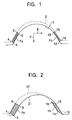
- a reference roll caliber 1 is shown by a solid line and an actual roll caliber 2 is shown by a broken line.
- Sensing positions are located at a 3-5 portion and a 13-15 portion on the reference roll caliber 1.
- Sensing positions are located at a 4-6 portion and a 14-16 portion located on the actual roll caliber 2.
- These portions on the reference roll caliber 1 are called a reference profile, and these portions on the actual roll caliber 2 are called an actually measured profile.
- Fa the area of the hatched portion defined by 3-5-6-4
- Fab the area of the hatched portion defined by 13-15-16-14 is denoted by Fb.
- a rolling reduction is shown by an arrow 7 and a roll axial direction is shown by an arrow 8.
- the areas Fa and Fb are represented by negative values, whereas when the actually measured profile is located above the reference profiles, the areas Fa and Fb are represented by positive values.
- the setting of the positive values and the negative values are not limited to the above setting.
- both Fa and Fb are set to positive values.
- an actual roll position is dislocated upward from a reference roll position by an amount proportional to the sum of the actual and reference roll positions.
- both Fa and Fb are set to negative values.
- the actual roll position is dislocated downward from the reference roll position by an amount proportional to the sum of the actual and reference roll positions.
- a roll is dislocated leftward in the roll axial direction in Fig. 1, it can be found that it is in coincidence with the Fa side, that is, the side having a larger area. Accordingly, it can be found that the roll is dislocated to the side having the larger area by an amount proportional to the difference between Fa and Fb.
- the sum of Fa and Fb is proportional to the location discrepancy of the roll in the rolling reduction direction. Further, the difference between Fa and Fb is proportional to the roll axial direction. Moreover, the directions in which the roll is dislocated can be determined depending upon whether the sum of, and the difference between, Fa and Fb is positive or negative.
- the roll can be adjusted to an ideal position by adjusting the position thereof in the rolling reduction direction and in the roll axial direction so that the sum of, and the difference between, Fa and Fb approach zero from the amounts of location discrepancy in the two directions, and the directions of location discrepancy, which have been determined as described above.
- the amounts of adjustment and the adjusting directions are called guidances.
- Fig. 3 shows an exemplary embodiment in which the present invention is employed in a two-roll rolling mill for rolling wire rod and steel bar.
- An illuminating device 32 is mounted on a guide mounting surface on the inlet side of the rolling mill so as to illuminate the calibers of rolls 31 along a rolling direction.
- a video input device is mounted on a guide mounting surface on the outlet side of the rolling mill.
- a CCD camera 33 is mounted on the video input device.
- the video of each caliber of the rolls 31 is input to the CCD camera 33, and the video signal of the CCD camera 33 can be supplied to a determining device that can be a calculating device 34.
- the calculating device 34 includes an image processing device 35 and a guidance calculating device 36.
- the image processing device 35 subjects the video signals from the CCD camera 33 to image processing, such as binary processing and the like, and extracts the actually measured profile of a sensing position and supplies the coordinates of the profile to the guidance calculating device 36.
- a coordinate system used in the calculating device 34 uses the center of a caliber as a point of origin, a roll axial direction is set on the X-axis, and a rolling reduction direction is set on the Y-axis as shown, for example, in Fig. 4.
- the coordinates of the reference profile of each roll 31 to be processed are preset to the guidance calculating device 36.
- the guidance calculating device 36 calculates the respective areas Fa and Fb between the reference profile and the actually measured profile at the right and left sensing positions based on the coordinates of the reference profile at the sensing positions and the coordinates of the actually measured profile supplied from the image processing device 35. Subsequently, the guidance calculating device 36 calculates the amount of location discrepancy S R in the rolling reduction direction and the amount of location discrepancy S A in the roll axial direction from the following formulae (1) and (2). S R and S A can be supplied to a display 37 (Fig. 3) as guidances. The absolute values of S R and S A correspond to the amounts of guidance and the positive and negative signs of S R and S A correspond to guidance directions.
- S R K 1 ⁇ (Fa + Fb)
- S A K 2 ⁇ (Fa-Fb) where, K 1 and K 2 are proportionality constants.
- the values S R , and S A which approximate actual amounts of location discrepancy, are displayed as the guidances.
- the guidances are not limited to these guidances and may be displayed by being converted into amounts of operation, such as angles of rotation and operating directions, or the like.
- material escaping portions are used as the sensing positions in the embodiment.
- the material escaping portions are located at both of the ends of each caliber in the roll axial direction, that is, a 3-5 portion and a 13-15 portion, which are actually measured on one of the roll calibers as shown in Fig. 4.
- a roll position is adjusted by the following procedure using the apparatus as described above.
- the example required only two minutes to process the upper and lower rolls using the portions 1.0 mm and 6.0 mm from both of the ends of the rolls as sensing positions until S R ⁇ 0.5 and S A ⁇ 0.25.
- the deviation of a rolled material diameter was less than 0.1 mm during this time.
- the roll positions of a pair of upper and lower rolls can be simply adjusted to approach or reach target positions in a short amount of time only by repeatedly moving the roll positions according to the guidances displayed on the display regardless of the degree of skill of the worker.
- the dimensional accuracy of a product greatly depends on the roll position adjusting job in the rolling of bar steel. Because an amount of adjustment (amount of guidance) of a roll position can be simply displayed quantitatively during the image processing, the roll position can be adjusted with high accuracy in a short amount of time without the need of a skilled worker.
- Fig. 5 shows the calibers of an embodiment of a three-roll rolling mill.
- Fig. 6 shows the calibers of an embodiment of a four-roll rolling mill. Similar numerals as used in Fig. 4 are used in Figs. 5 and 6.
- the procedures used in these three-roll and four-roll rolling mills are the same as those used in the two-roll rolling mill and the number of repetitions of the procedures is changed depending upon the number of rolls.
- the caliber of a roll for rolling bar steel has a complex overall shape.
- the profile of the caliber at the center of the caliber is not included in the sensing positions.
- the profile of an overall roll caliber need not be necessarily extracted in the image processing.
- the image processing can be effectively carried out by extracting a profile of only a portion of the roll caliber.
- the location discrepancy of a roll and the dislocating direction of the roll can be provided as guidances by the sum of, and the difference between, the areas Fa and Fb, which are calculated from the profiles at the sensing positions. Accordingly, the cost of the overall apparatus can be reduced.
- the portions of the roll caliber that are less worn by rolling are used as the sensing positions of the embodiment. Therefore, an error due to wear can be reduced to a low level, and an accurate position of the roll can be determined.
- the material escaping portion used as the sensing position of the embodiment has an approximately linear or smooth curved profile.
- Fa and Fb the areas Fa' and Fb' of the squares, which are surrounded by four coordinates in total; that is, the coordinates at both of the ends of the reference profile and the coordinates at both of the ends of the actually measured profile.
- a worker adjusts a roll position based on the values displayed on the display 37 in Fig. 3.
- the fine adjustment of the roll position may be automatically carried out by operating a roll position adjusting apparatus in association with the value output from the guidance calculating device 36 in Fig 3.
- an amount of adjustment of a roll position can be accurately determined by the present invention, which can have a simple arrangement. As a result, the roll position can be simply and accurately adjusted.
- the use of the material escaping portion, having a small degree of wear due to rolling and a non-complex profile, as the sensing position can further enhance the accuracy of the amount of adjustment of the roll position.
Landscapes
- Engineering & Computer Science (AREA)
- Mechanical Engineering (AREA)
- Control Of Metal Rolling (AREA)
- Length Measuring Devices By Optical Means (AREA)
- Reduction Rolling/Reduction Stand/Operation Of Reduction Machine (AREA)
- Length Measuring Devices With Unspecified Measuring Means (AREA)
Abstract
Description
Claims (15)
- A method of adjusting a roll position in a rolling mill, comprising:selecting two portions of a caliber of a roll as sensing positions, the two portions being located at approximately symmetrical positions with respect to a rolling reduction direction of the roll;determining the sum of, and the difference between, areas located between a reference profile and an actually measured profile at the sensing positions; and adjusting the roll position based on the determined sum of, and the difference between, the areas located between the reference profile and the actually measured profile at the sensing positions.
- The method of claim 1, wherein the bar steel rolling mill is a two-roll bar steel rolling mill.
- The method of claim 1, wherein the bar steel rolling mill is a three-roll bar steel rolling mill.
- The method of claim 1, wherein the bar steel rolling mill is a four-roll bar steel rolling mill.
- The method of any preceding claim, wherein the sensing positions are located at material escaping portions at each of two opposed ends of the roll in an axial direction of the roll.
- The method of any preceding claim, wherein the actually measured profiles at the sensing positions of the roll are determined by inputting video signals of the sensing positions, and subjecting the video signals at the sensing positions to image processing.
- The method of any preceding claim, further comprising:determining a first guidance in the rolling reduction direction from the sum of the areas located between the actually measured profiles and the reference profiles at the sensing positions;determining a second guidance in the roll axial direction from the difference between the areas located between the actually measured profiles and the reference profiles at the sensing positions; and adjusting the roll position in the rolling reduction direction and the roll axial direction based on the first guidance and the second guidance, respectively.
- A roll position adjusting guidance apparatus, comprising:an illuminating device that illuminates a caliber of a roll;a video signal input device that inputs video signals of sensing positions of the roll caliber at portions of the roll caliber located approximately symmetrically with respect to a rolling reduction direction of the roll;an image processing apparatus that determines actually measured profiles of the sensing positions based on the video signals; anda determining device that determines (a) a guidance in the rolling reduction direction from the sum of the areas located between the actually measured profiles and the reference profiles at the sensing positions, and (b) a guidance in the roll axial direction from the difference between the areas located between the actually measured profiles and the reference profiles at the sensing positions.
- A method of adjusting a roll position in a rolling mill, comprising:(a) illuminating a caliber of a roll;(b) inputting video signals of sensing positions of the roll caliber located at portions of the roll caliber located approximately symmetrically with respect to a rolling reduction direction of the roll;(c) determining actually measured profiles of the sensing positions based on the video signals; and(d) determining a first guidance in the rolling reduction direction from the sum of the areas located between the actually measured profiles and the reference profiles at the sensing positions;(e) determining a second guidance in the roll axial direction from the difference between the areas located between the actually measured profiles and the reference profiles at the sensing positions; and(f) adjusting the roll position in the rolling reduction direction and the roll axial direction based on the first guidance and the second guidance, respectively.
- The method of claim 9, wherein the rolling mill is a two-roll bar steel rolling mill.
- The method of claim 9, wherein the rolling mill is a three-roll bar steel rolling mill.
- The method of claim 9, wherein the rolling mill is a four-roll bar steel rolling mill.
- The method of any of claims 9 to 12, wherein the sensing positions are located at material escaping portions at each of two opposed ends of the roll in an axial direction of the roll.
- The method of any of claims 9 to 13, further comprising repeating steps (a)-(f) until absolute values of the first and second guidances are equal to a value within a desired range.
- The method of claim 14, wherein the value is zero.
Applications Claiming Priority (2)
| Application Number | Priority Date | Filing Date | Title |
|---|---|---|---|
| JP4228199 | 1999-02-19 | ||
| JP04228199A JP3873505B2 (en) | 1999-02-19 | 1999-02-19 | Roll position adjustment method and roll position adjustment guidance device for rolling roll for steel bars |
Publications (2)
| Publication Number | Publication Date |
|---|---|
| EP1029605A2 true EP1029605A2 (en) | 2000-08-23 |
| EP1029605A3 EP1029605A3 (en) | 2003-11-05 |
Family
ID=12631680
Family Applications (1)
| Application Number | Title | Priority Date | Filing Date |
|---|---|---|---|
| EP00301039A Withdrawn EP1029605A3 (en) | 1999-02-19 | 2000-02-09 | Roll position adjustment |
Country Status (6)
| Country | Link |
|---|---|
| US (1) | US6216518B1 (en) |
| EP (1) | EP1029605A3 (en) |
| JP (1) | JP3873505B2 (en) |
| KR (1) | KR20000058084A (en) |
| AU (1) | AU752923B2 (en) |
| TW (1) | TW473407B (en) |
Cited By (1)
| Publication number | Priority date | Publication date | Assignee | Title |
|---|---|---|---|---|
| WO2006045629A1 (en) * | 2004-10-29 | 2006-05-04 | Vai Pomini S.R.L. | Device and method for aligning the input apparatuses and the channels in a rolling stand |
Families Citing this family (8)
| Publication number | Priority date | Publication date | Assignee | Title |
|---|---|---|---|---|
| JP3612711B2 (en) | 2002-07-03 | 2005-01-19 | トヨタ自動車株式会社 | Automobile |
| JP4300518B2 (en) * | 2003-10-07 | 2009-07-22 | 住友金属工業株式会社 | Multi-stage rolling mill misalignment measuring device |
| JP4752014B2 (en) * | 2006-05-24 | 2011-08-17 | 株式会社神戸製鋼所 | Strip rolling method |
| KR101141013B1 (en) * | 2009-03-26 | 2012-05-02 | 현대제철 주식회사 | Apparatus for error measuring of rolling mill for section shape steel |
| WO2013041083A2 (en) * | 2011-09-23 | 2013-03-28 | Sms Meer Gmbh | Rolling mill and rolling method |
| CN104233660B (en) * | 2014-10-10 | 2016-08-17 | 星菱缝纫机(宁波)有限公司 | A kind of intelligence zipper sewing machine |
| JP7338732B1 (en) * | 2022-03-31 | 2023-09-05 | Jfeスチール株式会社 | Roll information calculation device, roll information calculation method, rolling equipment adjustment method, and round bar product manufacturing method |
| KR102523049B1 (en) * | 2022-05-12 | 2023-04-19 | 한국기계연구원 | Roller gap measuring system using a light and method for measuring roller gap using the same |
Family Cites Families (6)
| Publication number | Priority date | Publication date | Assignee | Title |
|---|---|---|---|---|
| US3574280A (en) * | 1968-11-12 | 1971-04-13 | Westinghouse Electric Corp | Predictive gauge control method and apparatus with adaptive plasticity determination for metal rolling mills |
| SE371757B (en) * | 1972-02-07 | 1974-12-02 | Morgaardshammar Ab | |
| GB1511558A (en) * | 1975-07-18 | 1978-05-24 | British Steel Corp | Optical roll alignment device |
| DE4137451C2 (en) * | 1991-11-14 | 1994-07-14 | Kocks Technik | Method and device for setting three rollers or guide rollers forming a common caliber opening |
| JP2595413B2 (en) | 1992-05-08 | 1997-04-02 | 新日本製鐵株式会社 | Method and apparatus for measuring shape of roll caliber |
| JPH085343A (en) | 1994-06-16 | 1996-01-12 | Sumitomo Metal Ind Ltd | Roll caliber measurement adjustment equipment |
-
1999
- 1999-02-19 JP JP04228199A patent/JP3873505B2/en not_active Expired - Fee Related
-
2000
- 2000-02-04 US US09/497,479 patent/US6216518B1/en not_active Expired - Fee Related
- 2000-02-09 EP EP00301039A patent/EP1029605A3/en not_active Withdrawn
- 2000-02-11 TW TW089102352A patent/TW473407B/en not_active IP Right Cessation
- 2000-02-17 KR KR1020000007523A patent/KR20000058084A/en not_active Ceased
- 2000-02-21 AU AU18445/00A patent/AU752923B2/en not_active Ceased
Cited By (2)
| Publication number | Priority date | Publication date | Assignee | Title |
|---|---|---|---|---|
| WO2006045629A1 (en) * | 2004-10-29 | 2006-05-04 | Vai Pomini S.R.L. | Device and method for aligning the input apparatuses and the channels in a rolling stand |
| CN101052480B (en) * | 2004-10-29 | 2010-12-22 | 西门子Vai金属技术有限公司 | Apparatus and method for aligning a feeding device and a channel in a rolling stand |
Also Published As
| Publication number | Publication date |
|---|---|
| TW473407B (en) | 2002-01-21 |
| KR20000058084A (en) | 2000-09-25 |
| US6216518B1 (en) | 2001-04-17 |
| JP3873505B2 (en) | 2007-01-24 |
| EP1029605A3 (en) | 2003-11-05 |
| AU752923B2 (en) | 2002-10-03 |
| AU1844500A (en) | 2000-08-24 |
| JP2000237808A (en) | 2000-09-05 |
Similar Documents
| Publication | Publication Date | Title |
|---|---|---|
| EP0289084B2 (en) | Non-contact determination of the position of a rectilinear feature of an article | |
| US5933231A (en) | Method and system for measuring cavities and probe for use therein | |
| US6216518B1 (en) | Method of adjusting position in bar steel rolling mill and roll position adjusting guidance apparatus | |
| EP3995222A1 (en) | Inappropriate quality judgment apparatus and inappropriate quality judgment method | |
| EP4231232B1 (en) | Strip shape determining apparatus for metal strip, rolling mill, and determination method | |
| CN110220481B (en) | Handheld visual detection equipment and pose detection method thereof | |
| RU2389574C2 (en) | Device and method to position loaders and calibers at rolling mill stand | |
| EP1018633A2 (en) | Bar angle measurement system | |
| KR100373679B1 (en) | Camber measuring device and method for controlling camber using the device in hot rolling | |
| EP0722078A2 (en) | Gob measuring apparatus | |
| US4805019A (en) | Non-contact apparatus and method for measuring the length of aluminum sheet and plate | |
| JP3147797B2 (en) | Video non-contact extensometer | |
| KR20040058742A (en) | Optimal target shape decision system and its method for improving flatness of cold rolled strip | |
| JP5024102B2 (en) | Roll caliber position detection device and roll caliber position detection method | |
| KR100433256B1 (en) | Apparatus for measuring the sectional shape of the rolled bar | |
| JPS63134903A (en) | Measuring instrument for flatness of rolled stock | |
| JPH1144518A (en) | Caliber shape measuring device and shape adjusting method | |
| JPH04167911A (en) | Device for controlling plate bending in hot roughing mill | |
| KR20060130026A (en) | Size measurement method using digital camera | |
| KR100523219B1 (en) | Method for measuring dog-bone profile of bar using both CCD camera and laser slit beam in hot strip mill | |
| JP3620891B2 (en) | Thin film evaluation apparatus and thin film evaluation method | |
| JPH04178209A (en) | Device for controlling bent of plate on hot finish rolling mill | |
| JPH06258027A (en) | Position detecting method of plate member using tv camera | |
| JP5458606B2 (en) | Roll caliber position detection device and roll caliber position detection method | |
| JPS6244202B2 (en) |
Legal Events
| Date | Code | Title | Description |
|---|---|---|---|
| PUAI | Public reference made under article 153(3) epc to a published international application that has entered the european phase |
Free format text: ORIGINAL CODE: 0009012 |
|
| AK | Designated contracting states |
Kind code of ref document: A2 Designated state(s): AT BE CH CY DE DK ES FI FR GB GR IE IT LI LU MC NL PT SE |
|
| AX | Request for extension of the european patent |
Free format text: AL;LT;LV;MK;RO;SI |
|
| PUAL | Search report despatched |
Free format text: ORIGINAL CODE: 0009013 |
|
| AK | Designated contracting states |
Kind code of ref document: A3 Designated state(s): AT BE CH CY DE DK ES FI FR GB GR IE IT LI LU MC NL PT SE |
|
| AX | Request for extension of the european patent |
Extension state: AL LT LV MK RO SI |
|
| RIC1 | Information provided on ipc code assigned before grant |
Ipc: 7B 21B 31/16 B Ipc: 7B 21B 38/10 B Ipc: 7B 21B 38/00 A |
|
| RAP1 | Party data changed (applicant data changed or rights of an application transferred) |
Owner name: JFE STEEL CORPORATION |
|
| AKX | Designation fees paid | ||
| REG | Reference to a national code |
Ref country code: DE Ref legal event code: 8566 |
|
| STAA | Information on the status of an ep patent application or granted ep patent |
Free format text: STATUS: THE APPLICATION IS DEEMED TO BE WITHDRAWN |
|
| 18D | Application deemed to be withdrawn |
Effective date: 20040507 |