EP1029158B1 - Device for controlling a gas shuttle valve for internal combustion engines - Google Patents
Device for controlling a gas shuttle valve for internal combustion engines Download PDFInfo
- Publication number
- EP1029158B1 EP1029158B1 EP99916743A EP99916743A EP1029158B1 EP 1029158 B1 EP1029158 B1 EP 1029158B1 EP 99916743 A EP99916743 A EP 99916743A EP 99916743 A EP99916743 A EP 99916743A EP 1029158 B1 EP1029158 B1 EP 1029158B1
- Authority
- EP
- European Patent Office
- Prior art keywords
- valve
- pressure
- gas exchange
- valve member
- electrical control
- Prior art date
- Legal status (The legal status is an assumption and is not a legal conclusion. Google has not performed a legal analysis and makes no representation as to the accuracy of the status listed.)
- Expired - Lifetime
Links
Images
Classifications
-
- F—MECHANICAL ENGINEERING; LIGHTING; HEATING; WEAPONS; BLASTING
- F01—MACHINES OR ENGINES IN GENERAL; ENGINE PLANTS IN GENERAL; STEAM ENGINES
- F01L—CYCLICALLY OPERATING VALVES FOR MACHINES OR ENGINES
- F01L9/00—Valve-gear or valve arrangements actuated non-mechanically
- F01L9/10—Valve-gear or valve arrangements actuated non-mechanically by fluid means, e.g. hydraulic
Definitions
- the invention relates to a control device a gas exchange valve for internal combustion engines.
- a control device a gas exchange valve for internal combustion engines.
- Control device is a piston-shaped valve member axially displaceable in a housing, the Valve member at its end near the combustion chamber a plate-shaped Has valve sealing surface with which it with a valve seat fixed to the housing for controlling an inlet or Exhaust cross section at the combustion chamber of the to be supplied Internal combustion engine interacts.
- the valve member On his distant combustion chamber Shaft end, the valve member has a hydraulic piston on, two hydraulic work rooms in the axial direction separates from one another, a lower one, near the combustion chamber Workspace the valve member of the gas exchange valve in Closing direction and an upper work area that is far from the combustion chamber acts on the valve member in the opening direction.
- the upper work space is over one included an electrical control valve High pressure supply line and another one Electrical control valve contained discharge line alternately can be filled with high pressure and relieved.
- the Gas exchange valve is now controlled by filling of the upper work area, whereby when open Control valve in the high pressure supply line Pressure medium of high pressure in the upper work area flows, the force application surface on the piston of the Valve member of the gas exchange valve is larger than that Force application area in the lower work area, so that the Piston and with it the valve member in the opening direction below and so the opening cross section on Open valve member seat.
- the discharge line of the upper workspace is meanwhile through the second Control valve closed. It is now targeted by Actuation of the control valves in the High pressure supply line and the relief line on upper working space of the gas exchange valve member possible, to realize different opening positions and that Gas exchange valve member by opening the control valve in the discharge line back onto its valve seat move back.
- the known control device for Gas exchange valves have the disadvantage that the Valve element in the event of a failure of the pressure supply system in its open valve member position can remain so that there is a risk that the gas exchange valve member with the piston of the internal combustion engine in its upper Dead center collides. This can block the entire valve train and the heaviest mechanical Cause damage to the internal combustion engine itself and also affected by the possible blocking of the Drive axles on the driven motor vehicle also Vehicle occupant safety.
- WO 96 121 09 A discloses a device for Control of gas exchange valves on the actuating piston of the gas exchange valves hydraulically with pressure on both sides are acted upon, the bottom of the Actuating piston continuously with a pressure accumulator and the Pressure side of a pump is connected and the top of the Actuating piston using either a solenoid valve the pressure side of the pump or a relief line connected is.
- the inventive device for controlling a Gas exchange valve for internal combustion engines with the features of claim 1 has the advantage that a hydraulically actuated valve actuator concept available is provided, even if the Pressure supply device or the electrical Control of the control valves a persistence of Avoid gas exchange valve member in the open position and returning the valve member to its closed position guaranteed.
- a first measure is implemented in that the electrical control valves in the high pressure supply line and in the relief line of the upper, the opening movement of the gas exchange valve member effecting work space are switched in the de-energized state so that the upper Working area on the piston of the gas exchange valve member is depressurized is.
- the gas exchange valve member ensures working space, that the valve member in the de-energized state of the control valves is held securely in contact with the valve seat.
- the for the opening stroke movement of the gas exchange valve member The responsible hydraulic work area can only be energized the electric control valves are filled with high pressure, so that the gas exchange valve only if it works properly Switching valves can be opened.
- a working pressure accumulator is on the Valve control device provided, which preferably as Spring pressure accumulator is designed and in particular for Maintaining a predetermined stand pressure in the Control device is used.
- This should Working pressure accumulator preferably a possible one Leakage loss during the parking of the to be supplied Compensate internal combustion engine and a stand pressure maintained immediately with the start of operation of the Internal combustion engine a safe function of the Control device guaranteed. Furthermore done a smoothing of the working pressure accumulator System pressure fluctuations during operation.
- a check valve in one High pressure supply line from one Pressure supply device provided in the direction Gas exchange valve member opens, and the Working pressure accumulator and a branch line in the lower Work area are connected downstream in the flow direction.
- the electrical control valves are more advantageous Formed as solenoid valves by a electrical control unit depending on Operating parameters of the internal combustion engine to be supplied can be controlled.
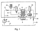
- Figure 1 shows a schematic representation of a Embodiment of the control device in which in addition to the working pressure accumulator also an emergency pressure accumulator the lower working space of the control piston is connected and thus all the proposed Safety devices are shown.
- the device shown schematically in FIG Control of a gas exchange valve for internal combustion engines has a gas exchange valve 1 for controlling an inlet or Exhaust cross-section on a combustion chamber not one internal combustion engine shown in more detail.
- the Gas exchange valve 1 has an axial in a housing 3 Slidable valve member 5 on its lower, Valve-shaped end on the combustion chamber side, a valve sealing surface 7, with which it is used to control a Opening cross section with a valve seat 8 am Housing of the internal combustion engine interacts.
- the Valve member 5 has on its upper, facing away from the combustion chamber End of a cross-sectional expansion forming a piston 9 with which the valve member 5 two hydraulic Working spaces in the housing 3 axially separates from each other.
- a Pressure supply device For supplying pressure to the control device with a Pressure medium high pressure is still one Pressure supply device provided in Embodiment by a regulated high pressure pump 19th is formed, which the pressure medium, preferably oil a reservation 21 into a high pressure supply line 23 promotes.
- the high pressure pump 19 can be on the suction side or be regulated on the pressure side.
- a pressure storage space as a high pressure medium source then use a variety of High pressure supply lines to the individual Control devices of the individual gas exchange valves dissipate.
- the original part of the high pressure supply line 23 opens in the upper hydraulic work space 15, being between the branch into the branch line 25 and the junction in the upper work space 15 a first electrical Control valve 27 in the high pressure supply line 23 is used.
- a working pressure accumulator 29 in the flow direction in front of the first control valve 27 in the High pressure feed line 23 used as Spring pressure accumulator is formed.
- Relief line 33 which in the reservoir 21st opens and into which a second electrical control valve 35 is used, through which the relief line 33rd is lockable.
- Relief line 33rd In order to empty the line here too 33 and the upper work area 15 is to be avoided continues to open towards reservoir 21
- Check valve 36 inserted into the relief line 33.
- the lower working chamber 11 is also connected to an emergency pressure accumulator 37.
- This designed as a spring pressure accumulator 37 is dimensioned so that after reaching the detection threshold for the drop in the supply pressure and including the closing losses of the check valve 31 there is still enough pressure and volume for the closing process of the actuator in the pressure accumulator.
- the function of the emergency pressure accumulator 37 can be integrated into the control device according to the invention in addition to the working pressure accumulator 29, but it is alternatively also possible to take over the emergency pressure accumulator function through the working pressure accumulator 29 or to provide only the emergency pressure accumulator 37 on the control system.
- the working pressure accumulator 29 and the emergency pressure accumulator 37 work together at different pressure levels, the working pressure accumulator 29 working with a higher restoring torque at a higher pressure level.
- the working pressure accumulator 29 also takes on the task of smoothing the working pressure so that undesired pressure fluctuations in the system can be compensated for.
- the different pressure levels at the spring accumulators of the two pressure accumulators 29, 37 are set by different return springs, the spring of the emergency pressure accumulator 37 having the lower spring force.
- an emergency closing spring 39 is also required in the lower work space 11 used.
- This emergency closing spring 39 is a compression spring formed between a lower paragraph of the housing and the lower piston ring face 13 is clamped and the thus the valve member 5 of the gas exchange valve 1 in Closing direction applied.
- This emergency spring is 39 just so powerfully dimensioned that it is among all Conditions overcome the frictional moments in the gas exchange valve and the piston 9 on the valve member 5 from each Actuator position can move out into the closed position.
- the inventive device for controlling a Gas exchange valve of an internal combustion engine works in following way.
- a pressure medium preferably High pressure oil into the high pressure supply line 23.
- This high pressure passes through the check valve 31 and the continuously open branch line 25 in the lower hydraulic work chamber 11, which is on the lower Piston ring face 13 the valve member 5 in its after holding position directed above.
- the closed position of the gas exchange valve 1 are the electrical control valves 27 and 35 are de-energized, the first control valve 27 being the High-pressure supply line 23 into the upper working space 15 closes.
- the second control valve 35 is in a de-energized state Condition open, so that from the upper work area 15 laxative discharge line 33 in the Pressure fluid reserve 21 is open. That way the valve member 5 by the pressure in the lower working space 11 pressed to its valve seat 8. In the upper pressure chamber 15 only the ambient pressure. Now that The first control valve 27 opens the gas exchange valve 1 energized in the high pressure supply line 23 and thus opened while the second control valve 35 through a Energizing is locked. This now flows through it Pressure fluid in the upper work area 15. Since the upper Pressure area 17 of the piston 9 is larger than the lower one Printing area 13 and the pressure in both workrooms 15, 11 is approximately the same, now shifts the resulting one Pressure force after the valve member 5 of the gas exchange valve 1 down to its open position.
- the opening cross section of the gas exchange valve is opened.
- the control valve 27 closed and thus the supply of pressure medium in the upper work space 15 interrupted.
- the targeted Driving the electric control valves 27 and 35 are preferably designed as a solenoid valve, in Dependency on operating parameters of the internal combustion engine all by means of an electrical control unit Set valve opening positions.
Landscapes
- Engineering & Computer Science (AREA)
- Mechanical Engineering (AREA)
- General Engineering & Computer Science (AREA)
- Valve Device For Special Equipments (AREA)
Description
Die Erfindung geht aus von einer Vorrichtung zur Steuerung eines Gaswechselventils für Brennkraftmaschinen. Bei einer derartigen aus der DE-A-195 11 320 bekannten Steuerungsvorrichtung ist ein kolbenförmiges Ventilglied axial verschiebbar in einem Gehäuse geführt, wobei das Ventilglied an seinem brennraumnahen Ende eine tellerförmige Ventildichtfläche aufweist, mit der es mit einem gehäusefesten Ventilsitz zur Steuerung eines Einlaß- bzw. Auslaßquerschnittes am Brennraum der zu versorgenden Brennkraftmaschine zusammenwirkt. An seinem brennraumfernen Schaftende weist das Ventilglied einen hydraulischen Kolben auf, der in Achsrichtung zwei hydraulische Arbeitsräume voneinander trennt, von denen ein unterer, brennraumnaher Arbeitsraum das Ventilglied des Gaswechselventils in Schließrichtung und ein oberer, brennraumferner Arbeitsraum das Ventilglied in Öffnungsrichtung beaufschlagt. Dabei ist der untere Arbeitsraum über eine Hochdruckzuführungsleitung ständig mit einer Hochdruckquelle verbunden und somit mit Hochdruck beaufschlagt. Der obere Arbeitsraum ist über eine ein elektrisches Steuerventil enthaltene Hochdruckzuführungsleitung und eine ein weiteres elektrisches Steuerventil enthaltene Entlastungsleitung wechselnd mit Hochdruck befüllbar und entlastbar. Das Gaswechselventil wird nunmehr durch das gesteuerte Befüllen des oberen Arbeitsraumes betätigt, wobei bei geöffnetem Steuerventil in der Hochdruckzuführungsleitung ein Druckmittel hohen Druckes in den oberen Arbeitsraum einströmt, dessen Kraftangriffsfläche am Kolben des Ventilgliedes des Gaswechselventiles größer ist als die Kraftangriffsfläche im unteren Arbeitsraum, so daß der Kolben und mit ihm das Ventilglied in Öffnungsrichtung nach unten verschoben werden und so den Öffnungsquerschnitt am Ventilgliedsitz aufsteuern. Die Entlastungsleitung des oberen Arbeitsraumes ist währenddessen durch das zweite Steuerventil verschlossen. Es ist nunmehr durch das gezielte Ansteuern der Steuerventile in der Hochdruckzuführungsleitung und der Entlastungsleitung am oberen Arbeitsraum des Gaswechselventilgliedes möglich, verschiedene Öffnungsstellungen zu realisieren und das Gaswechselventilglied durch Aufsteuern des Steuerventils in der Entlastungsleitung wieder auf seinen Ventilsitz zurückzubewegen.The invention relates to a control device a gas exchange valve for internal combustion engines. At a such known from DE-A-195 11 320 Control device is a piston-shaped valve member axially displaceable in a housing, the Valve member at its end near the combustion chamber a plate-shaped Has valve sealing surface with which it with a valve seat fixed to the housing for controlling an inlet or Exhaust cross section at the combustion chamber of the to be supplied Internal combustion engine interacts. On his distant combustion chamber Shaft end, the valve member has a hydraulic piston on, two hydraulic work rooms in the axial direction separates from one another, a lower one, near the combustion chamber Workspace the valve member of the gas exchange valve in Closing direction and an upper work area that is far from the combustion chamber acts on the valve member in the opening direction. It is the lower work area via a high pressure supply line permanently connected to a high pressure source and thus with High pressure applied. The upper work space is over one included an electrical control valve High pressure supply line and another one Electrical control valve contained discharge line alternately can be filled with high pressure and relieved. The Gas exchange valve is now controlled by filling of the upper work area, whereby when open Control valve in the high pressure supply line Pressure medium of high pressure in the upper work area flows, the force application surface on the piston of the Valve member of the gas exchange valve is larger than that Force application area in the lower work area, so that the Piston and with it the valve member in the opening direction below and so the opening cross section on Open valve member seat. The discharge line of the upper workspace is meanwhile through the second Control valve closed. It is now targeted by Actuation of the control valves in the High pressure supply line and the relief line on upper working space of the gas exchange valve member possible, to realize different opening positions and that Gas exchange valve member by opening the control valve in the discharge line back onto its valve seat move back.
Dabei weist die bekannte Steuerungsvorrichtung für Gaswechselventile jedoch den Nachteil auf, daß das Ventilglied bei einem Ausfall des Druckversorgungssystems in seiner geöffneten Ventilgliedstellung verbleiben kann, so daß die Gefahr besteht, daß das Gaswechselventilglied mit dem Kolben der Brennkraftmaschine in dessen oberer Totpunktlage kollidiert. Dies kann zum Blockieren des gesamten Ventiltriebes und zu schwersten mechanischen Schäden an der Brennkraftmaschine selbst führen und beeinträchtigt zudem durch das mögliche Blockieren der Antriebsachsen am angetriebenen Kraftfahrzeug auch die Sicherheit der Fahrzeuginsassen. The known control device for Gas exchange valves, however, have the disadvantage that the Valve element in the event of a failure of the pressure supply system in its open valve member position can remain so that there is a risk that the gas exchange valve member with the piston of the internal combustion engine in its upper Dead center collides. This can block the entire valve train and the heaviest mechanical Cause damage to the internal combustion engine itself and also affected by the possible blocking of the Drive axles on the driven motor vehicle also Vehicle occupant safety.
Bekannt ist durch die WO 96 121 09 A eine Vorrichtung zur Steuerung von Gaswechselventilen, bei der Betätigungskolben der Gaswechselventile beidseitig hydraulisch mit Druck beaufschlagbar sind, wobei die Unterseite des Betätigungskolbens dauernd mit einem Druckspeicher und der Druckseite einer Pumpe verbunden ist und die Oberseite des Betätigungskolbens mittels eines Magnetventiles entweder mit der Druckseite der Pumpe oder einer Entlastungsleitung verbunden ist.WO 96 121 09 A discloses a device for Control of gas exchange valves on the actuating piston of the gas exchange valves hydraulically with pressure on both sides are acted upon, the bottom of the Actuating piston continuously with a pressure accumulator and the Pressure side of a pump is connected and the top of the Actuating piston using either a solenoid valve the pressure side of the pump or a relief line connected is.
Bei einer durch die EP-A-0 736 671 bekannten Vorrichtung zur Steuerung von Gaswechselventilen werden ebenfalls Betätigungskolben der Gaswechselventile beidseitig hydraulisch mit Druck beaufschlagt, wobei die Unterseite des Betätigungskolbens dauernd mit der Druckseite einer Hochdruckpumpe verbunden ist und von einer Druckfeder beaufschlagt wird, während die Oberseite des Betätigungskolbens über ein erstes Magnetventil mit der Hochdruckpumpe und über ein zweites Magnetventil mit einer Niederdruckpumpe verbindbar ist. In a device known from EP-A-0 736 671 for Control of gas exchange valves will also be Actuating piston of the gas exchange valves on both sides hydraulically pressurized, the bottom of the Actuating piston permanently with the pressure side of one High pressure pump is connected and by a compression spring is applied while the top of the Actuating piston via a first solenoid valve with the High pressure pump and a second solenoid valve with a Low pressure pump is connectable.
Die erfindungsgemäße Vorrichtung zur Steuerung eines Gaswechselventils für Brennkraftmaschinen mit den Merkmalen des Patentanspruchs 1 hat demgegenüber den Vorteil, daß ein hydraulisch betätigbares Ventilstellerkonzept zur Verfügung gestellt wird, das auch bei einem Ausfall der Druckversorgungseinrichtung beziehungsweise der elektrischen Ansteuerung der Steuerventile ein Verharren des Gaswechselventilgliedes in Öffnungsposition sicher vermeidet und eine Rückführung des Ventilgliedes in seine Schließlage gewährleistet. Dabei werden drei Sicherheitsmaßnahmen vorgeschlagen, die aus Sicherheitsgründen erst in gemeinsamer Anwendung ein optimales Sicherheitskonzept darstellen.The inventive device for controlling a Gas exchange valve for internal combustion engines with the features of claim 1 has the advantage that a hydraulically actuated valve actuator concept available is provided, even if the Pressure supply device or the electrical Control of the control valves a persistence of Avoid gas exchange valve member in the open position and returning the valve member to its closed position guaranteed. There are three security measures proposed that for security reasons only in common Represent an optimal security concept.
Eine erste Maßnahme wird dabei dadurch realisiert, daß die elektrischen Steuerventile in der Hochdruckzuführungsleitung und in der Entlastungsleitung des oberen, die Öffnungsbewegung des Gaswechselventilgliedes bewirkenden Arbeitsraumes in stromlosem Zustand so geschaltet sind, daß der obere Arbeitsraum am Kolben des Gaswechselventilgliedes druckentlastet ist. Somit ist bei ständig mit der Hochdruckzuführungsleitung verbundenem unterem, in Schließrichtung auf das Gaswechselventilglied wirkenden Arbeitsraum gewährleistet, daß das Ventilglied in stromlosem Zustand der Steuerventile sicher in Anlage am Ventilsitz gehalten wird. Der für die Öffnungshubbewegung des Gaswechselventilgliedes zuständige hydraulische Arbeitsraum kann erst mit Bestromen der elektrischen Steuerventile mit Hochdruck gefüllt werden, so daß das Gaswechselventil nur bei einwandfrei funktionierenden Schaltventilen aufsteuerbar ist. Bei elektrischen Problemen zum Beispiel einem Kabelabfall zum Steller, Kurzschlüssen in den Ansteuerleitungen und so weiter genügt es, die Steuerventile beziehungsweise deren Ansteuerung stromlos zu schalten. Dabei ist es besonders vorteilhaft, daß für ein Bewegen des Gaswechselventilgliedes in die kritische Öffnungsposition zwei voneinander unabhängige Aktionen notwendig sind, nämlich das aktive Schließen des elektrischen Steuerventils in der Entlastungsleitung und das Aufsteuern des elektrischen Steuerventils in der Hochdruckzuführungsleitung. Da der für die Schließbewegung des Ventilgliedes des Gaswechselventiles zuständige Arbeitsraum ständig mit der Hochdruckzuführungsleitung verbunden ist, befindet sich in dem für das Schließen verantwortlichen Pfad kein elektrisches Bauteil, das ausfallen kann.A first measure is implemented in that the electrical control valves in the high pressure supply line and in the relief line of the upper, the opening movement of the gas exchange valve member effecting work space are switched in the de-energized state so that the upper Working area on the piston of the gas exchange valve member is depressurized is. Thus, is with the high pressure supply line at all times connected lower, in the closing direction the gas exchange valve member ensures working space, that the valve member in the de-energized state of the control valves is held securely in contact with the valve seat. The for the opening stroke movement of the gas exchange valve member The responsible hydraulic work area can only be energized the electric control valves are filled with high pressure, so that the gas exchange valve only if it works properly Switching valves can be opened. With electrical problems for example a cable waste to the actuator, short circuits in the control lines and so on, it is enough to Control valves or their control is de-energized turn. It is particularly advantageous that for a Moving the gas exchange valve member into the critical Opening position two independent actions are necessary, namely the active closing of the electrical control valve in the relief line and that Open the electrical control valve in the High-pressure supply line. Because of the closing movement responsible for the valve member of the gas exchange valve Workspace with the high pressure supply line at all times is in the for closing responsible path no electrical component that can fail.
Darüber hinaus ist ein Arbeitsdruckspeicher an der Ventilsteuerungsvorrichtung vorgesehen, der vorzugsweise als Federdruckspeicher ausgebildet ist und der insbesondere zur Aufrechterhaltung eines vorbestimmten Standdruckes in der Steuereinrichtung dient. Dabei soll dieser Arbeitsdruckspeicher vorzugsweises einen möglichen Leckageverlust während des Abstellens der zu versorgenden Brennkraftmaschine ausgleichen und einen Standdruck aufrechterhalten, der sofort mit Beginn des Betriebs der Brennkraftmaschine eine sichere Funktion der Steuerungseinrichtung gewährleistet. Desweiteren erfolgt durch den Arbeitsdruckspeicher ein Glätten der Druckschwankungen im System während des Betriebs.In addition, a working pressure accumulator is on the Valve control device provided, which preferably as Spring pressure accumulator is designed and in particular for Maintaining a predetermined stand pressure in the Control device is used. This should Working pressure accumulator preferably a possible one Leakage loss during the parking of the to be supplied Compensate internal combustion engine and a stand pressure maintained immediately with the start of operation of the Internal combustion engine a safe function of the Control device guaranteed. Furthermore done a smoothing of the working pressure accumulator System pressure fluctuations during operation.
Um ein Abströmen des Speicherdruckes in der Hochdruckversorgung der Steuereinrichtung zu vermeiden ist desweiteren ein Rückschlagventil in einer Hochdruckzuführungsleitung von einer Druckversorgungseinrichtung vorgesehen, das in Richtung Gaswechselventilglied öffnet, und dem der Arbeitsdruckspeicher und eine Zweigleitung in den unteren Arbeitsraum in Strömungsrichtung nachgeschaltet sind.To discharge the storage pressure in the High pressure supply to the control device is to be avoided further a check valve in one High pressure supply line from one Pressure supply device provided in the direction Gas exchange valve member opens, and the Working pressure accumulator and a branch line in the lower Work area are connected downstream in the flow direction.
Eine weitere Maßnahme zur sicheren Rückstellung und zum Halten des Gaswechselventilgliedes in der unkritischen Schließlage wird durch das Vorsehen einer Notfeder am Gaswechselventilglied erreicht, die bei Ausfall des gesamten Druckversorgungssystems und einem Druckabfall auch in den hydraulischen Arbeitsräumen am Kolben des Ventilgliedes dieses in seine Schließlage zurückführt. Dabei ist diese Notfeder als Druckfeder ausgebildet, die in den unteren, für die Schließbewegung des Ventilgliedes verantwortlichen hydraulischen Arbeitsraum eingesetzt ist und dort in Schließrichtung am Ventilgliedkolben angreift. Die Feder ist gerade so dimensioniert, daß sie unter allen Bedingungen die Reibkräfte im Stellglied überwinden und den Gaswechselgliedkolben aus jeder Position heraus in die sichere Schließposition verschieben kann.Another measure for safe resetting and Keeping the gas exchange valve member in the uncritical The closed position is provided by the provision an emergency spring on Gas exchange valve member reached in the event of failure of the entire Pressure supply system and a pressure drop also in the hydraulic working spaces on the piston of the valve member this returns to its closed position. Here is this Emergency spring designed as a compression spring, which in the lower, for the closing movement of the valve member responsible hydraulic work area is used and there attacks in the closing direction on the valve member piston. The spring is just dimensioned so that it is under all Conditions overcome the frictional forces in the actuator and the Gas exchange piston from any position in the can move the safe closing position.
Mit dem vorgeschlagenen Steuerungssystem für ein Gaswechselventil für Brennkraftmaschinen ist somit gewährleistet, daß auch bei einem Ausfall des Steuerungssystems das Gaswechselventilglied sicher in seine Schließlage zurückverschoben wird, so daß eine Kollision des Gaswechselventilgliedes mit dem Kolben der Brennkraftmaschine sicher vermieden werden kann.With the proposed control system for a Gas exchange valve for internal combustion engines is thus ensures that even if the Control system the gas exchange valve member safely in its Closing position is moved back, so that a collision of the Gas exchange valve member with the piston of Internal combustion engine can be safely avoided.
Die elektrischen Steuerventile sind dabei in vorteilhafter Weise als Magnetventile ausgebildet, die von einem elektrischen Steuergerät in Abhängigkeit von Betriebsparametern der zu versorgenden Brennkraftmaschine angesteuert werden.The electrical control valves are more advantageous Formed as solenoid valves by a electrical control unit depending on Operating parameters of the internal combustion engine to be supplied can be controlled.
Eine weitere erfindungsgemäße Möglichkeit zur Verschiebung des Gaswechselventilgliedes in seine Schließstellung bei Ausfall der Steuereinrichtung wird durch das Vorsehen eines Notspeichers erreicht, der direkt mit dem unteren, für die Schließbewegung verantwortlichen hydraulischen Arbeitsraum verbunden ist. Dieser vorzugsweise als Federspeicher ausgebildete Notspeicherraum speichert dabei lediglich soviel Volumen an Hochdruckmittel, wie benötigt wird, um das Gaswechselventilglied in seine Schließposition zu verschieben. Another possibility for displacement according to the invention the gas exchange valve member in its closed position Failure of the control device is caused by the provision of a Emergency storage reached directly with the lower one for the Closing motion responsible hydraulic work space connected is. This preferably as a spring accumulator trained emergency storage space only stores as much volume of high pressure medium as is required to Gas exchange valve member in its closed position move.
Weitere Vorteile und vorteilhafte Ausgestaltungen des Gegenstandes der Erfindung sind der Beschreibung, den Patentansprüchen und der Zeichnung entnehmbar.Further advantages and advantageous configurations of the The invention relates to the description of the Claims and the drawing can be seen.
Ein Ausführungsbeispiel der erfindungsgemäßen Vorrichtung zur Steuerung eines Gaswechselventils für Brennkraftmaschinen ist in der Zeichnung dargestellt und in der nachfolgenden Beschreibung näher erläutert.An embodiment of the device according to the invention to control a gas exchange valve for Internal combustion engines is shown in the drawing and in the following description explained.
Die Figur 1 zeigt eine schematische Darstellung eines Ausführungsbeispiels der Steuerungsvorrichtung, bei der neben dem Arbeitsdruckspeicher auch ein Notdruckspeicher an den unteren Arbeitsraum des Stellkolbens angeschlossen ist und bei dem somit sämtliche vorgeschlagenen Sicherheitseinrichtungen gezeigt sind.Figure 1 shows a schematic representation of a Embodiment of the control device in which in addition to the working pressure accumulator also an emergency pressure accumulator the lower working space of the control piston is connected and thus all the proposed Safety devices are shown.
Die in der Figur 1 schematisch dargestellte Vorrichtung zur
Steuerung eines Gaswechselventils für Brennkraftmaschinen
weist ein Gaswechselventil 1 zur Steuerung eines Einlaßoder
Auslaßquerschnittes an einem Brennraum einer nicht
näher dargestellten Brennkraftmaschine auf. Das
Gaswechselventil 1 weist dabei ein in einem Gehäuse 3 axial
verschiebbares Ventilglied 5 auf, das an seinem unteren,
brennraumseitigen tellerförmigen Ende eine Ventildichtfläche
7 aufweist, mit der es zur Steuerung eines
Öffnungsquerschnittes mit einer Ventilsitzfläche 8 am
Gehäuse der Brennkraftmaschine zusammenwirkt. Das
Ventilglied 5 weist an seinem oberen, brennraumabgewandten
Ende eine, einen Kolben 9 bildende Querschnittserweiterung
auf, mit der das Ventilglied 5 zwei hydraulische
Arbeitsräume im Gehäuse 3 axial voneinander trennt. Dabei
beaufschlagt ein unten liegender, brennraumnaher
hydraulischer Arbeitsraum 11 das Ventilglied 5 an einer
unteren Kolbenringstirnfläche 13 in Schließrichtung des
Gaswechselventils 1. Ein oben liegender brennraumferner
Arbeitsraum 15 beaufschlagt das nach unten öffnende
Ventilglied 5 in Öffnungsrichtung, wobei der Druck im oberen
Arbeitsraum 15 an der gesamten oberen Kolbenstirnfläche 17
angreift.The device shown schematically in FIG
Control of a gas exchange valve for internal combustion engines
has a gas exchange valve 1 for controlling an inlet or
Exhaust cross-section on a combustion chamber not one
internal combustion engine shown in more detail. The
Gas exchange valve 1 has an axial in a
Zur Druckversorgung der Steuerungsvorrichtung mit einem
Druckmittel hohen Druckes ist weiterhin eine
Druckversorgungseinrichtung vorgesehen, die im
Ausführungsbeispiel durch eine geregelte Hochdruckpumpe 19
gebildet wird, die das Druckmittel, vorzugsweise Öl aus
einem Reservat 21 in eine Hochdruckzuführungsleitung 23
fördert. Die Hochdruckpumpe 19 kann dabei saugseitig oder
druckseitig geregelt sein. Alternativ ist es auch möglich
einen Druckspeicherraum als Hochdruckmittelquelle zu
verwenden, von dem dann eine Vielzahl von
Hochdruckzuführungsleitungen zu den einzelnen
Steuerungsvorrichtungen der einzelnen Gaswechselventile
abführen.For supplying pressure to the control device with a
Pressure medium high pressure is still one
Pressure supply device provided in
Embodiment by a regulated high pressure pump 19th
is formed, which the pressure medium, preferably oil
a
Von der Hochdruckzuführungsleitung 23 zweigt an der
Steuerungsvorrichtung eine Zweigleitung 25 ab, die in den
unteren hydraulischen Arbeitsraum 11 einmündet. Der
ursprüngliche Teil der Hochdruckzuführungsleitung 23 mündet
in den oberen hydraulischen Arbeitsraum 15, wobei zwischen
der Abzweigung in die Zweigleitung 25 und die Einmündung in
den oberen Arbeitsraum 15 ein erstes elektrisches
Steuerventil 27 in die Hochdruckzuführungsleitung 23
eingesetzt ist. Desweiteren ist ein Arbeitsdruckspeicher 29
in Strömungsrichtung vor dem ersten Steuerventil 27 in die
Hochdruckzuführungsleitung 23 eingesetzt, der als
Federdruckspeicher ausgebildet ist. Zur Gewährleistung eines
vorbestimmten Standdruckes in der Hochdruckzuführungsleitung
23 und der mit dieser verbundenen Zweigleitung 25 und zum
Vermeiden des Abströmens von Druckmittel aus diesen
Leitungen im Falle einer Havarie ist weiterhin ein
Rückschlagventil 31 in Strömungsrichtung vor die Verzweigung
in die Zweigleitung 25, den Arbeitsdruckspeicher 29 und das
erste Steuerventil 27 in die Hochdruckzuführungsleitung 23
eingesetzt.From the high
Desweiteren führt vom oberen Arbeitsraum 15 eine
Entlastungsleitung 33 ab, die in das Vorratsreservoir 21
mündet und in die ein zweites elektrisches Steuerventil 35
eingesetzt ist, durch das die Entlastungsleitung 33
verschließbar ist. Um auch hier ein Leerströmen der Leitung
33 und des oberen Arbeitsraumes 15 zu vermeiden, ist
weiterhin ein in Richtung Reservoir 21 öffnendes
Rückschlagventil 36 in die Entlastungsleitung 33 eingesetzt.Furthermore, leads from the
Um bei einem Druckabfall im Hochdruckleitungssystem ein
sicheres Rückkehren des Ventilgliedes 5 des
Gaswechselventils 1 an seinen gehäusefesten Ventilsitz 8 zu
gewährleisten, ist der untere Arbeitsraum 11 zudem mit einem
Notdruckspeicher 37 verbunden. Dieser als Federdruckspeicher
ausgebildete Notdruckspeicher 37 ist dabei so dimensioniert,
daß nach dem Erreichen der Erkennungsschwelle für das
Abfallen des Versorgungsdrucks und einschließlich der
Schließverluste des Rückschlagventils 31 noch genügend Druck
und Volumen für den Schließvorgang des Stellgliedes im
Druckspeicher übrigbleibt. Dabei kann die Funktion des
Notdruckspeichers 37 zusätzlich zum Arbeitsdruckspeicher 29
in die erfindungsgemäße Steuerungsvorrichtung integriert
sein, es ist alternativ jedoch auch möglich, die
Notdruckspeicherfunktion durch den Arbeitsdruckspeicher 29
mit zu übernehmen bzw. nur den Notdruckspeicher 37 am
Steuersystem vorzusehen.
Der Arbeitsdruckspeicher 29 und der Notdruckspeicher 37
arbeiten beim gemeinsamen Vorsehen dabei auf
unterschiedlichen Druckniveaustufen, wobei der
Arbeitsdruckspeicher 29 mit einem höheren Rückstellmoment
auf einem höheren Druckniveau arbeitet. Dabei übernimmt der
Arbeitsdruckspeicher 29 neben dem Erhalt des Restdruckes
auch die Aufgabe eines Glättens des Arbeitsdruckes, so daß
unerwünschte Druckschwankungen im System ausgeglichen werden
können. Die unterschiedlichen Druckniveaus an den
Federspeichern der beiden Druckspeicher 29, 37 werden dabei
durch unterschiedliche Rückstellfedern eingestellt, wobei
die Feder des Notdruckspeichers 37 die geringere Federkraft
aufweist.
Um das Ventilglied 5 des Gaswechselventils 1 nach einer
vollständigen Druckentlastung des Drucksystems durch eine
geringe Leckage zum Beispiel bei längerem Abstellen der zu
versorgenden Brennkraftmaschine, bei dem auch die
Druckspeicher 29 und 37 entleert werden, in der
Schließposition zu halten ist desweiteren eine
Notschließfeder 39 in den unteren Arbeitsraum 11 eingesetzt. In order to ensure a safe return of the
The working
In order to keep the
Diese Notschließfeder 39 ist dabei als Druckfeder
ausgebildet, die zwischen einem unteren Gehäuseabsatz und
der unteren Kolbenringstirnfläche 13 eingespannt ist und die
somit das Ventilglied 5 des Gaswechselventils 1 in
Schließrichtung beaufschlagt. Dabei ist diese Notfeder 39
gerade so kräftig dimensioniert, daß sie unter allen
Bedingungen die Reibmomente im Gaswechselventil überwinden
und den Kolben 9 am Ventilglied 5 aus jeder
Stellgliedposition heraus in die Schließlage bewegen kann.This
Die erfindungsgemäße Vorrichtung zur Steuerung eines
Gaswechselventils einer Brennkraftmaschine arbeitet in
folgender Weise. Mit Beginn des Betriebs der
Brennkraftmaschine fördert die von dieser vorzugsweise
angetriebene Hochdruckpumpe 19 ein Druckmittel, vorzugsweise
Öl unter hohem Druck in die Hochdruckzuführungsleitung 23.
Dabei gelangt dieser Hochdruck über das Rückschlagventil 31
und die ständig geöffnete Zweigleitung 25 in den unteren
hydraulischen Arbeitsraum 11, der dabei über die untere
Kolbenringstirnfläche 13 das Ventilglied 5 in seiner nach
oben gerichteten Schließlage hält. In Ruhe- beziehungsweise
Schließposition des Gaswechselventils 1 sind dabei die
elektrischen Steuerventile 27 und 35 stromlos geschaltet,
wobei das erste Steuerventil 27 dabei die
Hochdruckzuführungsleitung 23 in den oberen Arbeitsraum 15
verschließt. Das zweite Steuerventil 35 ist in stromlosem
Zustand offengeschaltet, so daß die vom oberen Arbeitsraum
15 abführende Entlastungsleitung 33 in das
Druckmittelreservat 21 geöffnet ist. Auf diese Weise wird
das Ventilglied 5 durch den Druck im unteren Arbeitsraum 11
an seinen Ventilsitz 8 gepreßt. Im oberen Druckraum 15 liegt
lediglich der Umgebungsdruck an. Um nunmehr das
Gaswechselventil 1 zu öffnen wird das erste Steuerventil 27
in der Hochdruckzuführungsleitung 23 bestromt und somit
geöffnet, während das zweite Steuerventil 35 durch ein
Bestromen verschlossen wird. Dadurch strömt nunmehr das
Druckmittel in den oberen Arbeitsraum 15. Da die obere
Druckfläche 17 des Kolbens 9 größer ist als die untere
Druckfläche 13 und der Druck in beiden Arbeitsräumen 15, 11
annähernd gleich ist, verschiebt nunmehr die resultierende
Druckkraft das Ventilglied 5 des Gaswechselventils 1 nach
unten in seine Öffnungsposition. Dabei wird durch das
Abheben der Ventildichtfläche 7 vom Ventilsitz 8 am Gehäuse
der Öffnungsquerschnitt des Gaswechselventils aufgesteuert.
Um das Gaswechselventilglied 5 in einer bestimmten
Öffnungsposition zu fixieren, wird das Steuerventil 27
geschlossen und damit die Zufuhr von Druckmittel in dem
oberen Arbeitsraum 15 unterbrochen. Das
Gaswechselventilglied 5 kommt infolgedessen zum Stillstand
wenn die Resultierende der Druckkräfte in den Arbeitsräumen
11 und 15 im Zusammenwirken mit den Rückstellkräften am
Ventilglied 5 Null ist. Dabei lassen sich durch das gezielte
Ansteuern der elektrischen Steuerventile 27 und 35, die
vorzugsweise als Magnetventil ausgebildet sind, in
Abhängigkeit von Betriebsparametern der Brennkraftmaschine
mittels eines elektrischen Steuergerätes sämtliche
Ventilöffnungspositionen einstellen.The inventive device for controlling a
Gas exchange valve of an internal combustion engine works in
following way. With the start of operation of the
Internal combustion engine preferably promotes this
driven high pressure pump 19 a pressure medium, preferably
High pressure oil into the high
Um das Gaswechselventil 1 wieder zu schließen, wird bei
weiterhin verschlossenem ersten Steuerventil 27 das zweite
Steuerventil 35 in der Entlastungsleitung 33 geöffnet.
Dadurch sinkt der Druck im oberen Arbeitsraum 15 auf nahezu
Umgebungsdruckniveau, während im unteren Arbeitsraum 11
weiterhin der hohe Systemdruck anliegt. Da das Produkt aus
Druck und Druckfläche im unteren Arbeitsraum 11 nunmehr
größer ist als im oberen Arbeitsraum 15, wird der Kolben 9
und somit das Ventilglied 5 des Gaswechselventils 1 durch
die resultierende Kraft erneut in Schließlage verschoben und
mit der Ventildichtfläche 7 in den Ventilsitz 8 gepreßt. Der
Ruhezustand ist somit wieder erreicht und ein neuer
Arbeitszyklus kann erfolgen. Dabei verbleibt im sich
stromabwärts an das Rückschlagventil 31 anschließenden
Druckleitungssystem in den unteren Arbeitsraum 11 der
Druckmittelhochdruck.To close the gas exchange valve 1 again, at
further closed
Claims (4)
- Device for controlling a gas exchange valve for internal combustion engines, with an axially displaceable valve member (5) which has, at its end near the combustion space, a valve sealing surface (7), by means of which it cooperates with a valve seat (8) fixed to the housing, the said valve member having, at its end remote from the combustion space, a piston (9) which axially separates from one another two hydraulic working spaces, of which a lower working space (11) near the combustion space acts upon the valve member (5) in the closing direction and an upper working space (15) remote from the combustion space acts upon the valve member (5) in the opening direction, the lower working space (11) being constantly connected to a high-pressure source (19), and the upper working space (15) being capable of being alternately filled with high pressure and relieved via a high-pressure supply line (23) containing a first electrical control valve (27) and via a relief line (33) containing a second electrical control valve (35), and the first electrical control valve (27), in the currentless state, closing the high-pressure supply line (23) into the upper working space (15), and the second electrical control valve (35), in the currentless state, holding the relief line (33) open, the high-pressure source (19) conveying a hydraulic working medium under pressure into the high-pressure supply line (23), from which a branch line (25) leads away into the lower working space (11), upstream of the first electrical control valve (27) in the direction of flow, and into which a non-return valve (31) opening in the direction of flow is inserted upstream of the branch-off of the branch line (25) in the direction of flow, and to which a working-pressure accumulator (29) preferably designed as a spring accumulator is connected, and there being provided on the gas exchange valve (1) an emergency spring (39) which is designed as a compression spring and which acts upon the gas exchange valve member (5) in the direction of its closing movement and/or keeps it in the closing position and which is clamped in the lower working space (11) between a housing shoulder and the piston (9) on the valve member (5) of the gas exchange valve (1).
- Device according to Claim 1, characterized in that the electrical control valves (27, 35) in the high-pressure supply line (23) and the relief line (33) are designed as solenoid valves which are activated by an electrical control apparatus as a function of operation parameters of the internal combustion engine to be supplied.
- Device according to Claim 1, characterized in that the high-pressure source is designed as a pump, preferably as a variable high-pressure pump (19).
- Device according to Claim 1, characterized in that the lower working space (11) is connected to an emergency pressure accumulator (37) preferably designed as a spring accumulator.
Applications Claiming Priority (3)
| Application Number | Priority Date | Filing Date | Title |
|---|---|---|---|
| DE19826047 | 1998-06-12 | ||
| DE19826047A DE19826047A1 (en) | 1998-06-12 | 1998-06-12 | Device for controlling a gas exchange valve for internal combustion engines |
| PCT/DE1999/000427 WO1999066179A1 (en) | 1998-06-12 | 1999-02-16 | Device for controlling a gas shuttle valve for internal combustion engines |
Publications (2)
| Publication Number | Publication Date |
|---|---|
| EP1029158A1 EP1029158A1 (en) | 2000-08-23 |
| EP1029158B1 true EP1029158B1 (en) | 2003-11-12 |
Family
ID=7870584
Family Applications (1)
| Application Number | Title | Priority Date | Filing Date |
|---|---|---|---|
| EP99916743A Expired - Lifetime EP1029158B1 (en) | 1998-06-12 | 1999-02-16 | Device for controlling a gas shuttle valve for internal combustion engines |
Country Status (6)
| Country | Link |
|---|---|
| US (1) | US6321703B1 (en) |
| EP (1) | EP1029158B1 (en) |
| JP (1) | JP2002518626A (en) |
| KR (1) | KR100589297B1 (en) |
| DE (2) | DE19826047A1 (en) |
| WO (1) | WO1999066179A1 (en) |
Families Citing this family (38)
| Publication number | Priority date | Publication date | Assignee | Title |
|---|---|---|---|---|
| ITBO20000548A1 (en) * | 2000-09-22 | 2002-03-22 | Magneti Marelli Spa | COMBUSTION ENGINE FOR MOTOR VEHICLES AND SIMILAR |
| US6739293B2 (en) * | 2000-12-04 | 2004-05-25 | Sturman Industries, Inc. | Hydraulic valve actuation systems and methods |
| AT411090B (en) * | 2000-12-12 | 2003-09-25 | Jenbacher Ag | FULLY VARIABLE HYDRAULIC VALVE ACTUATOR |
| DE10101584A1 (en) | 2001-01-16 | 2002-07-25 | Bosch Gmbh Robert | Pressure accumulator for pressurizing a hydraulic device, with which a gas exchange valve of an internal combustion engine is preferably actuated |
| DE10107698C1 (en) * | 2001-02-19 | 2002-08-22 | Bosch Gmbh Robert | Gas exchange valve device for an internal combustion engine |
| DE10136020A1 (en) | 2001-07-24 | 2003-02-13 | Bosch Gmbh Robert | Control device for IC engine gas changing valves has common electrically-operated control valves associated with each pair of hydraulic valve setting devices for respective gas changing valves |
| DE10138881A1 (en) * | 2001-08-08 | 2003-02-27 | Bosch Gmbh Robert | Method for operating an electro-hydraulic valve control of an internal combustion engine, computer program and control and regulating device for operating an internal combustion engine |
| DE10140528A1 (en) * | 2001-08-17 | 2003-02-27 | Bosch Gmbh Robert | Device for controlling gas exchange valves |
| DE10143330A1 (en) | 2001-09-05 | 2003-03-20 | Bosch Gmbh Robert | Internal combustion engine with electrohydraulic valve controler, has hydraulic load supplied with excess fluid from pump for producing volumetric fluid flow for valve controler |
| DE10143959A1 (en) | 2001-09-07 | 2003-03-27 | Bosch Gmbh Robert | Hydraulically controled actuator for valve, especially gas replacement valve in combustion engine, has control piston with area of working surface(s) changing along piston displacement path |
| DE10147299A1 (en) * | 2001-09-26 | 2003-04-24 | Bosch Gmbh Robert | Device for controlling an opening cross section in a combustion cylinder of an internal combustion engine |
| US6776129B2 (en) | 2001-10-19 | 2004-08-17 | Robert Bosch Gmbh | Hydraulic actuator for a gas exchange valve |
| DE10152503A1 (en) | 2001-10-24 | 2003-05-08 | Bosch Gmbh Robert | Device for controlling gas exchange valves |
| DE10155669A1 (en) | 2001-11-13 | 2003-05-22 | Bosch Gmbh Robert | Device for controlling at least one gas exchange valve |
| EP1468171A1 (en) | 2002-01-15 | 2004-10-20 | Robert Bosch Gmbh | Device for controlling a cross-section of an opening in the combustion cylinder of an internal combustion engine |
| DE10203275A1 (en) * | 2002-01-29 | 2003-08-07 | Bosch Gmbh Robert | Device for controlling gas exchange valves |
| DE10203273A1 (en) | 2002-01-29 | 2003-08-07 | Bosch Gmbh Robert | cylinder head |
| US20040020453A1 (en) * | 2002-02-05 | 2004-02-05 | Yager James H. | Damped valve controller |
| DE10210158A1 (en) | 2002-03-07 | 2003-09-18 | Bosch Gmbh Robert | Cylinder piston engine |
| DE10210334A1 (en) | 2002-03-08 | 2003-09-18 | Bosch Gmbh Robert | Device for controlling a gas exchange valve |
| DE10221566A1 (en) | 2002-05-15 | 2003-11-27 | Bosch Gmbh Robert | Filter for flowing viscous medium, especially hydraulic oil, has filter element with electric heater with heating wires distributed over filter element; wires are arranged on filter element surface |
| DE10226254A1 (en) | 2002-06-13 | 2003-12-24 | Bosch Gmbh Robert | Hydraulically controlled actuator for actuating an exhaust gas exchange valve of an internal combustion engine |
| DE10230478A1 (en) | 2002-07-06 | 2004-01-15 | Robert Bosch Gmbh | Device for controlling gas exchange valves |
| DE10239118A1 (en) | 2002-08-27 | 2004-03-04 | Robert Bosch Gmbh | Device for controlling at least one gas exchange valve of an internal combustion engine |
| DE10239747A1 (en) | 2002-08-29 | 2004-03-11 | Robert Bosch Gmbh | Hydraulic valve actuator for actuating a gas exchange valve |
| JP2004197588A (en) * | 2002-12-17 | 2004-07-15 | Mitsubishi Motors Corp | Valve system for internal combustion engine |
| DE10310300A1 (en) | 2003-03-10 | 2004-09-23 | Robert Bosch Gmbh | Combustion engine valve actuator control method, in which the work space of the actuator is temporarily connected to a hydraulic fluid accumulator to measure a resultant pressure drop and thus the position of the actuator element |
| US6959673B2 (en) * | 2003-04-02 | 2005-11-01 | General Motors Corporation | Engine valve actuator assembly with dual automatic regulation |
| EP1536107A1 (en) * | 2003-11-28 | 2005-06-01 | Thomas Friedhelm Buschkuehl | Valve operating apparatus and method for an engine |
| US7007644B2 (en) * | 2003-12-04 | 2006-03-07 | Mack Trucks, Inc. | System and method for preventing piston-valve collision on a non-freewheeling internal combustion engine |
| DE102004009461A1 (en) | 2004-02-27 | 2005-09-15 | Robert Bosch Gmbh | Valve |
| US7866286B2 (en) * | 2006-09-13 | 2011-01-11 | Gm Global Technology Operations, Inc. | Method for valve seating control for an electro-hydraulic engine valve |
| DE102007025619B4 (en) * | 2007-06-01 | 2012-11-15 | Robert Bosch Gmbh | Method and device for controlling a hydraulic actuator |
| DE102007048688A1 (en) | 2007-10-10 | 2009-04-16 | Uwe Hammer | Valve mechanism for internal combustion engine, has variable stroke of gas shuttle valve, which comprises transmission pin, rotating tilt lever and control piece |
| EP2063075A1 (en) * | 2007-11-23 | 2009-05-27 | EMPA Eidgenössische Materialprüfungs- und Forschungsanstalt | Fluid actuated valve mechanism |
| US9181825B2 (en) * | 2013-04-23 | 2015-11-10 | Edward Hall Batchelor, JR. | Internal combustion engine independent valve actuator |
| DE102013207863A1 (en) | 2013-04-30 | 2014-10-30 | Mahle International Gmbh | Device for controlling a gas exchange valve of an internal combustion engine |
| SE546024C2 (en) * | 2022-07-11 | 2024-04-16 | Freevalve Ab | An apparatus comprising a plurality of tools, wherein each tool comprises at least one hydraulic chamber |
Family Cites Families (7)
| Publication number | Priority date | Publication date | Assignee | Title |
|---|---|---|---|---|
| US4009695A (en) * | 1972-11-14 | 1977-03-01 | Ule Louis A | Programmed valve system for internal combustion engine |
| DE3836725C1 (en) * | 1988-10-28 | 1989-12-21 | Daimler-Benz Aktiengesellschaft, 7000 Stuttgart, De | |
| US4930465A (en) * | 1989-10-03 | 1990-06-05 | Siemens-Bendix Automotive Electronics L.P. | Solenoid control of engine valves with accumulator pressure recovery |
| JPH05202712A (en) * | 1992-01-30 | 1993-08-10 | Toyota Motor Corp | Hydraulic valve driving device of internal combustion engine |
| US5460129A (en) * | 1994-10-03 | 1995-10-24 | Ford Motor Company | Method to reduce engine emissions due to misfire |
| AU713548B2 (en) * | 1994-10-13 | 1999-12-02 | Nigel Eric Rose | Fluid actuated engines and engine mechanisms |
| US5572961A (en) * | 1995-04-05 | 1996-11-12 | Ford Motor Company | Balancing valve motion in an electrohydraulic camless valvetrain |
-
1998
- 1998-06-12 DE DE19826047A patent/DE19826047A1/en not_active Withdrawn
-
1999
- 1999-02-16 WO PCT/DE1999/000427 patent/WO1999066179A1/en active IP Right Grant
- 1999-02-16 KR KR1020007001409A patent/KR100589297B1/en not_active IP Right Cessation
- 1999-02-16 DE DE59907710T patent/DE59907710D1/en not_active Expired - Fee Related
- 1999-02-16 EP EP99916743A patent/EP1029158B1/en not_active Expired - Lifetime
- 1999-02-16 JP JP2000554970A patent/JP2002518626A/en active Pending
-
2000
- 2000-02-14 US US09/485,543 patent/US6321703B1/en not_active Expired - Fee Related
Also Published As
| Publication number | Publication date |
|---|---|
| KR100589297B1 (en) | 2006-06-14 |
| KR20010022808A (en) | 2001-03-26 |
| US6321703B1 (en) | 2001-11-27 |
| WO1999066179A1 (en) | 1999-12-23 |
| EP1029158A1 (en) | 2000-08-23 |
| DE19826047A1 (en) | 1999-12-16 |
| DE59907710D1 (en) | 2003-12-18 |
| JP2002518626A (en) | 2002-06-25 |
Similar Documents
| Publication | Publication Date | Title |
|---|---|---|
| EP1029158B1 (en) | Device for controlling a gas shuttle valve for internal combustion engines | |
| DE4311627B4 (en) | Fuel injection device for internal combustion engines | |
| EP0960274B1 (en) | Fuel injection device for internal combustion engines | |
| EP0455762B1 (en) | Electro-hydraulic control device for an internal-combustion engine valve | |
| WO2005014995A1 (en) | Injector for fuel injection systems of combustion engines, particularly direct injection diesel engines | |
| DE1916266A1 (en) | Electrohydraulic actuator | |
| WO2000039451A1 (en) | Fuel injection device for internal combustion engines | |
| DE19919432C2 (en) | Common rail injector | |
| WO2015051794A1 (en) | Hydraulic valve timing of an internal combustion engine | |
| DE3107004C2 (en) | Mold clamping device | |
| DE19813983A1 (en) | Valve for controlling liquids | |
| EP1598551A1 (en) | Fuel injection device | |
| EP1925812B1 (en) | Fuel injector valve for combustion engines | |
| EP1537300B1 (en) | Hydraulic valve actuator for actuating a gas exchange valve | |
| DE102009021668A1 (en) | Adjustment arrangement has control unit for actuating control element, like valve controls process flow or actuator adjusts device, where electric actuator is provided for proportional actuation of control element | |
| EP1485585B1 (en) | Device for controlling a gas exchange valve | |
| DE69709550T2 (en) | Fuel injection valve for internal combustion engines | |
| EP1392965B1 (en) | Pressure amplifier for a fuel injection device | |
| WO2007014734A1 (en) | Fuel injection system for an internal combustion engine | |
| DE10201167A1 (en) | Hydraulic valve actuating system for internal combustion engine, incorporates damping unit with piston pushed down by oil under pressure and returned by valve spring | |
| DE6918188U (en) | VALVE CONTROL DEVICE FOR COMBUSTION MACHINERY. | |
| DE102012012890B4 (en) | injector | |
| WO2005040594A1 (en) | Fuel injection valve for internal combustion engines | |
| DE1944177A1 (en) | Control of inlet and outlet valves of internal combustion engines by liquid | |
| WO2006079315A1 (en) | Directional control valve arrangement and fuel injection system |
Legal Events
| Date | Code | Title | Description |
|---|---|---|---|
| PUAI | Public reference made under article 153(3) epc to a published international application that has entered the european phase |
Free format text: ORIGINAL CODE: 0009012 |
|
| 17P | Request for examination filed |
Effective date: 20000623 |
|
| AK | Designated contracting states |
Kind code of ref document: A1 Designated state(s): DE FR GB IT |
|
| 17Q | First examination report despatched |
Effective date: 20030124 |
|
| GRAH | Despatch of communication of intention to grant a patent |
Free format text: ORIGINAL CODE: EPIDOS IGRA |
|
| GRAA | (expected) grant |
Free format text: ORIGINAL CODE: 0009210 |
|
| GRAS | Grant fee paid |
Free format text: ORIGINAL CODE: EPIDOSNIGR3 |
|
| AK | Designated contracting states |
Kind code of ref document: B1 Designated state(s): DE FR GB IT |
|
| REG | Reference to a national code |
Ref country code: GB Ref legal event code: FG4D Free format text: NOT ENGLISH |
|
| REF | Corresponds to: |
Ref document number: 59907710 Country of ref document: DE Date of ref document: 20031218 Kind code of ref document: P |
|
| PGFP | Annual fee paid to national office [announced via postgrant information from national office to epo] |
Ref country code: GB Payment date: 20040202 Year of fee payment: 6 |
|
| GBT | Gb: translation of ep patent filed (gb section 77(6)(a)/1977) |
Effective date: 20040211 |
|
| ET | Fr: translation filed | ||
| PLBE | No opposition filed within time limit |
Free format text: ORIGINAL CODE: 0009261 |
|
| STAA | Information on the status of an ep patent application or granted ep patent |
Free format text: STATUS: NO OPPOSITION FILED WITHIN TIME LIMIT |
|
| 26N | No opposition filed |
Effective date: 20040813 |
|
| PG25 | Lapsed in a contracting state [announced via postgrant information from national office to epo] |
Ref country code: IT Free format text: LAPSE BECAUSE OF NON-PAYMENT OF DUE FEES Effective date: 20050216 Ref country code: GB Free format text: LAPSE BECAUSE OF NON-PAYMENT OF DUE FEES Effective date: 20050216 |
|
| GBPC | Gb: european patent ceased through non-payment of renewal fee |
Effective date: 20050213 |
|
| PGFP | Annual fee paid to national office [announced via postgrant information from national office to epo] |
Ref country code: FR Payment date: 20090420 Year of fee payment: 11 Ref country code: DE Payment date: 20090417 Year of fee payment: 11 |
|
| REG | Reference to a national code |
Ref country code: FR Ref legal event code: ST Effective date: 20101029 |
|
| PG25 | Lapsed in a contracting state [announced via postgrant information from national office to epo] |
Ref country code: FR Free format text: LAPSE BECAUSE OF NON-PAYMENT OF DUE FEES Effective date: 20100301 |
|
| PG25 | Lapsed in a contracting state [announced via postgrant information from national office to epo] |
Ref country code: DE Free format text: LAPSE BECAUSE OF NON-PAYMENT OF DUE FEES Effective date: 20100901 |