EP1028492A1 - Connecting element - Google Patents
Connecting element Download PDFInfo
- Publication number
- EP1028492A1 EP1028492A1 EP00102584A EP00102584A EP1028492A1 EP 1028492 A1 EP1028492 A1 EP 1028492A1 EP 00102584 A EP00102584 A EP 00102584A EP 00102584 A EP00102584 A EP 00102584A EP 1028492 A1 EP1028492 A1 EP 1028492A1
- Authority
- EP
- European Patent Office
- Prior art keywords
- connecting element
- strip
- clamping
- connection
- approximately
- Prior art date
- Legal status (The legal status is an assumption and is not a legal conclusion. Google has not performed a legal analysis and makes no representation as to the accuracy of the status listed.)
- Withdrawn
Links
Images


Classifications
-
- H—ELECTRICITY
- H01—ELECTRIC ELEMENTS
- H01H—ELECTRIC SWITCHES; RELAYS; SELECTORS; EMERGENCY PROTECTIVE DEVICES
- H01H85/00—Protective devices in which the current flows through a part of fusible material and this current is interrupted by displacement of the fusible material when this current becomes excessive
- H01H85/02—Details
- H01H85/20—Bases for supporting the fuse; Separate parts thereof
- H01H85/203—Bases for supporting the fuse; Separate parts thereof for fuses with blade type terminals
- H01H85/2035—Bases for supporting the fuse; Separate parts thereof for fuses with blade type terminals for miniature fuses with parallel side contacts
-
- H—ELECTRICITY
- H01—ELECTRIC ELEMENTS
- H01R—ELECTRICALLY-CONDUCTIVE CONNECTIONS; STRUCTURAL ASSOCIATIONS OF A PLURALITY OF MUTUALLY-INSULATED ELECTRICAL CONNECTING ELEMENTS; COUPLING DEVICES; CURRENT COLLECTORS
- H01R13/00—Details of coupling devices of the kinds covered by groups H01R12/70 or H01R24/00 - H01R33/00
- H01R13/02—Contact members
- H01R13/10—Sockets for co-operation with pins or blades
- H01R13/11—Resilient sockets
-
- H—ELECTRICITY
- H01—ELECTRIC ELEMENTS
- H01R—ELECTRICALLY-CONDUCTIVE CONNECTIONS; STRUCTURAL ASSOCIATIONS OF A PLURALITY OF MUTUALLY-INSULATED ELECTRICAL CONNECTING ELEMENTS; COUPLING DEVICES; CURRENT COLLECTORS
- H01R43/00—Apparatus or processes specially adapted for manufacturing, assembling, maintaining, or repairing of line connectors or current collectors or for joining electric conductors
- H01R43/16—Apparatus or processes specially adapted for manufacturing, assembling, maintaining, or repairing of line connectors or current collectors or for joining electric conductors for manufacturing contact members, e.g. by punching and by bending
-
- H—ELECTRICITY
- H01—ELECTRIC ELEMENTS
- H01H—ELECTRIC SWITCHES; RELAYS; SELECTORS; EMERGENCY PROTECTIVE DEVICES
- H01H85/00—Protective devices in which the current flows through a part of fusible material and this current is interrupted by displacement of the fusible material when this current becomes excessive
- H01H85/02—Details
- H01H85/20—Bases for supporting the fuse; Separate parts thereof
- H01H2085/2085—Holders for mounting a fuse on a printed circuit
Definitions
- the invention relates to a connecting element for the production of electrical Connections between electrical components, especially relays or fuses, and connecting cables in motor vehicles.
- Such connecting elements are used, for example, in motor vehicles in addition, single fuses or multiple connections fuse units to be connected to connecting cables at fuse boxes, either in the form of cables or wires or in the form of on printed circuit boards or printed circuit boards.
- the connecting element as one piece Stamped / bent part is formed and at least one clamping receptacle for an electrical component and at least one with at least one connecting line connectable support section for the clamp receptacle comprises, the distance between the mutually facing inner sides of the clamping arms forming the clamping receptacle in the area of a common base section of mine is closer to the free than in one End of the clamping arms located area.
- the connecting element in the receiving area contact connections between the clamping arms of the clamping receptacle of the electrical components are inserted during the carrier section for the electrical contact with the respective connecting cable worries.
- the design as a stamped / bent part enables simple and fast automated production of the connecting element.
- the provision of a compared to the conditions at the recording area My distance between the clamp arms in the area of the common Base section allows the clamping arms to lie close together to punch out the starting material so that little material is needed.
- the one for receiving the contact connections of the electrical Components required greater distance in the recording area can by appropriate shaping of the clamping arms following the Punching process can be obtained.
- the invention is particularly advantageous when many fasteners are punched out of a continuous strip of material because there is a larger number of connecting elements per unit length can be obtained.
- the base section as on both sides approximately perpendicular outgoing from the one clamping arm Connection strips formed, each at its free ends one of two together forming the other clamp arm and preferably arm sections running approximately perpendicular to the connecting strip wearing.
- the carrier section is designed as a carrier strip, with at least a strip edge a plurality of preferably evenly spaced Clamping shots are preferably approximately perpendicular to the longitudinal axis of the strip stand out.
- Connecting element is that it is an endless strip is producible, which is wound into a supply roll and thus special can be stored and transported easily. For the production the electrical connections can then have a connecting element the required length or the required number of clamp receptacles be unwound from the supply roll and cut off.
- a connecting element according to the invention having a plurality of clamping receptacles is also used as a female terminal busbar, i.e. as a stripe Plug-in bus referred to, in which the power distribution on or from the individual clamp recordings via the common carrier strip he follows.
- the carrier strip can engage a separate connection element brought, which for electrical connection with, for example In the form of cables or wires existing connecting lines is used.
- the connecting element can also be a one-piece stamped / bent part be formed and for example by a clinching process with the Carrier strips are connected.
- the connecting element is preferably designed such that it is approximately Exit direction running parallel to the carrier strip of the connecting element for the connecting line or connecting lines. This advantageously enables a low construction.
- the connecting element can be in the form of an endless strip with one longitudinally repeating basic structure are produced, so that it is easily wound, stored and stored in a supply roll can be transported.
- each formed by an endless strip Supply roll a connecting element and a connecting element with the desired length is cut off and a coupling strip of the connecting element and a carrier strip of the connecting element with each other be engaged.
- both the cutting operations and the connection of Connection element and connecting element automatically and in one Machine.
- connection element which can be brought into engagement with the carrier strip
- the carrier strip with a printed circuit board, e.g. a fuse box to connect, for example in the terminal receptacles the connecting element plug-in fuses to one or more Connect conductor tracks.
- each associated with a clamping receptacle Contact protrusion protrudes.
- the connecting element can then with the contact projections in corresponding openings the board is inserted and soldered so that between the conductor tracks electrical connections on the circuit board and the clamp receptacles over the remaining one, also referred to below as the main strip Part of the carrier strip exist.
- the contact projections in one of their free end distant area are provided with an extension.
- This extension can be designed so that it is plugged onto a circuit board Connection element with the extensions on the circuit board. If, according to a preferred variant, the contact projections of one and the clamp recordings from the opposite strip edge stick out of the remaining main strip, then the main strip forms between the extensions of the contact projections bridges, under which conductor tracks can be passed, their contacting with the connecting element is not desired.
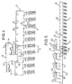
- Fig. 1 shows an embodiment of a connecting element according to the invention 10 in the punched and not yet bent state, in which it is still connected to a production strip 60 '.
- the connecting element 10 are separated from the production strip 16 'to individual connecting elements 10 to be obtained, which are shown in FIGS. 2 and 3 and described below.
- the punch can also be used in this way be formed so that the connecting element 10 before disconnection on one of the plug-in sections 27 or the contact pin explained below 23 is connected to the production strip 16 '.
- the connector 10 can be separated from a variety are obtained from endless strips having clamping receptacles, as he e.g. hereinafter in connection with FIGS. 4 and 5 or with 6 and 7 will be described.
- the connecting element 10 comprises a strip-shaped rectangular Clamping arm 20 and two strip-shaped clamping arm sections 18a and 18b, which together in the bent state of the connecting element 10 form a further clamping arm 18, which together with the Clamping arm 20 a clamping receptacle of the connecting element 10 for electrical contacts of electrical components, for example fuses, forms.
- the clamp arm 20 and the clamp arm sections 18a, 18b are in one common connecting strip 22 attached, from which they are each extend vertically.
- the distance a between the clamping arm 20 and the two clamp arm portions 18a, 18b is smaller than that, respectively Width of the clamping arm 20 and slightly larger than the width of the Clamp arm sections 18a, 18b.
- the distance a ' can also be smaller than that Width of the clamping arm sections 18a, 18b can be selected.
- clamping arm sections 18a, 18b are each with bevelled 19, which is preceded by an extension 21, from which the distance to the clamping arm 20 is smaller than the distance a ' in the region of a base section of the connecting element 10 Connecting strip 22 is.
- one of the plug-in sections 27 carries at its free end a contact pin 23.
- the connecting element 10 e.g. in a plastic housing be pressed in while it is made with such a Protruding contact pin 23 in a corresponding opening e.g. can be plugged into a circuit board or circuit board and soldered.
- Fig. 2 shows a side view of that separated from the production strip 16 ' Connecting element 10 in the final state, in which on the one hand the two Clamp arm sections 18a and 18b about 90 ° around the clamp arm 20 are bent around and on the other hand the clamping arm 20 approximately in one S shape is curved.
- Fig. 2 shows that that formed by the two clamping arm sections 18a, 18b Clamp arm 18 of the connecting element 10 according to the invention runs straight, while through the S-shape of the other clamping arm 20th created a clamp receptacle 14 with areas of different widths becomes.
- the clamping arm 20 runs in a straight line away from the other clamping arm 18 up to a first transition section 26, on which the clamping arm 20 is angled. From the first transition section 26 to a second, along with the other Clamping arm 18 forms a transition section in FIG Height of the extensions 21, the clamp arm 20 is straight and obliquely towards the clamping arm 18. From the clamping area 28 to his The free end of the clamping arm 20 in turn extends straight from the other Clamping arm 18 away so that it can be slanted together with the free ends of the clamping arm sections 18a, 18b a V-shaped receptacle forms.
- connection element 10 would correspond to the invention saved more than 20% in material.
- Fig. 4 shows a connection arrangement according to the invention, the connection element 10 and a connecting element 40 comprises. Both that Connecting element 10 and the connecting element 40 are made of one Continuous material stiffening with a repeating in the longitudinal direction Basic structure made.
- the carrier section of the connecting element 10 is supported by a carrier strip 16 formed in which positioning holes 36 for alignment with the connection element also having positioning holes 40 are provided.
- a variety of clamp receptacles 14 are like that Prongs of a comb from a side edge of the carrier strip 16 over Web 39 from that with the connecting strip 22 of the clamping receptacles 14 are connected. Different from the connecting element shown in FIG. 1 the webs 39 each extend one of the Clamping arm sections, i.e. the webs are attached laterally.
- the connecting element 40 comprises a coupling strip 44 for connection with the carrier strip 16 and a connecting strip 42 for connection to connecting lines, not shown.
- Deformations 38 indicate in Fig. 4 indicates that the coupling strip 44 and the carrier strip 16 by one Compression molding or clinching are brought into engagement with one another, the ones formed in the coupling strip 44 and in the carrier strip 16 Positioning holes 36 make it easy for the correct relative position between connecting element 10 and connecting element 40 to worry about.
- the connection between connecting element 10 and Connection element 40 can also be made by soldering or welding. In the assembled state according to FIG. 4, the connecting strips run 42 and the coupling strip 44 each parallel to the carrier strip 16, so that a departure direction indicated in Fig. 4 by the arrow K set for the connecting line parallel to the carrier strip 16 is.
- connection strips 42 and coupling strips 44 which in this embodiment are shorter than the clamp receptacles 14, a low height perpendicular to the individual strips 16, 42, 44 can be achieved.
- the connection between a connecting line and the connecting strip 42 takes place in a crimping or crimping process with the aid of tabs 41, 4 that the connecting strip 42 is trough-shaped is pre-bent to make it easy to pre-position the connecting cable enable.
- each of a supply roll to which both Connecting element 10 and the connecting element 40 after the Stamping and bending into the final shape for storage and Transport wrapped, the required length unwound, whereupon a single connecting element 10 and a single connecting element 40 can be cut to the desired length.
- connection arrangement according to the invention is shown in 5 indicated in the two connecting elements separated by a cut 50 10 can be seen, of which one six and the other has another ten clamp receptacles 14.
- connection elements 40 In the endless strip from which connection elements 40 are cut, can the terminal strip 42 already during the manufacture of the Endless strip e.g. be provided with cutting points 62 during punching, which separate connecting elements 40, which only later to Connect with individual connecting elements 10 by cuts 50 in Coupling strips 40 are finally separated from each other.
- 5 is also a connecting line to be connected to a connecting strip 42 60 shown.
- connection element 40 and Connection line 60 are preferably carried out automatically on a single machine. It is also possible to use such connecting elements 40 with connecting elements 10 bring into engagement, which in advance with connecting lines 60 have been connected.
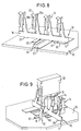
- FIG. 6 shows a connecting element 10 according to a further embodiment of the invention, which is the manufacture of another, hereinafter in connection with FIGS. 8 and 9 described connection arrangement allows the connection elements as described above were not required.
- FIG. 7 shows the connecting element 10 according to the invention from FIG. 6 in an enlarged view and from a different direction, wherein in particular the contact projections 32 can be seen, the one T-shape with a comparatively wide central beam and one of the Extension 33 formed crossbar. From Fig. 7 is further the lateral attachment of an extension of the clamping arm sections 18a webs 39 can be seen.
- the connecting element shown in FIGS. 6 and 7 can 10 can also be connected to a printed circuit board 70 the connecting lines to be contacted with the connecting element 10 60 and further lines 61 each in the form of conductor tracks are.
- the ones that form the T center bar are shown in FIG. 8 and FIG. 9 sections of the contact projections which cannot be seen corresponding openings are inserted in the circuit board 70, these openings are dimensioned such that the connecting element 10 with the Extensions 33 rests on the circuit board 70. Electrical connections to the conductor tracks running in the area of the contact projections 60 can be made by soldering.
- connecting element 10 with the extensions 33 on the circuit board 70 can through the gap between the circuit board 70 and that between two successive extensions 33 extending region of the main strip 17 such conductor tracks 61 are passed, which are not with the connecting element 10 should be contacted.
- connecting element 10 allows the use of a circuit board 70 which is low Has copper layer thickness, since the main current distribution through the Main strip 17 takes place and the circuit board 70 is not loaded.
- By the use of such inexpensive circuit boards 70 can be significant Cost reduction can be achieved.
- FIG. 9 shows how an electrical component 12, for example a fuse, via two connecting elements 10 according to the invention with a printed circuit board 70 can be connected.
- the right connecting element in FIG. 9 10 is provided with a plurality of clamping receptacles 14, of which only one of a plug contact 13 of the fuse 12 is used.
- a second plug contact 13 of the fuse 12 is in the terminal receptacle of a further connecting element 10, the clamp receptacle not one of many, from a common carrier strip outgoing terminal recordings, but as a separate connecting element 10 corresponding to the embodiment shown in FIGS. 2 and 3 the invention is formed.
- With its support section 16 is the connector 10 in the circuit board 70 to which it is Contacting with the desired conductor track are soldered can.
- the individual connecting element 10 can advantageously by Disconnect from a plurality of clamping receptacles 14 Continuous strips can be obtained, e.g. shown in Figs. 6 and 7 , being as the carrier section to be inserted into a printed circuit board 70 the contact protrusion 32 serves.
Abstract
Description
Die Erfindung betrifft ein Verbindungselement zur Herstellung von elektrischen Verbindungen zwischen elektrischen Bauteilen, insbesondere Relais oder Sicherungen, und Anschlußleitungen in Kraftfahrzeugen.The invention relates to a connecting element for the production of electrical Connections between electrical components, especially relays or fuses, and connecting cables in motor vehicles.
Derartige Verbindungselemente dienen beispielsweise in Kraftfahrzeugen dazu, einzelne Sicherungen oder mehrere Anschlüsse aufweisende Sicherungseinheiten an Sicherungskästen mit Anschlußleitungen zu verbinden, die entweder in Form von Kabeln bzw. Drähten oder in Form von auf Leiterplatten bzw. Platinen gedruckten Leiterplatten vorliegen.Such connecting elements are used, for example, in motor vehicles in addition, single fuses or multiple connections fuse units to be connected to connecting cables at fuse boxes, either in the form of cables or wires or in the form of on printed circuit boards or printed circuit boards.
Es ist das der Erfindung zugrundeliegende Problem (Aufgabe), eine möglichst einfache und mit einem möglichst geringen Materialverbrauch verbundene Möglichkeit zur Verbindung von elektrischen Bauteilen und Anschlußleitungen zu schaffen.It is the problem (task) on which the invention is based, one if possible simple and with the lowest possible material consumption Possibility to connect electrical components and connecting cables to accomplish.
Die Lösung dieser Aufgabe erfolgt durch die Merkmale des Anspruchs 1 und insbesondere dadurch, daß das Verbindungselement als einstückiges Stanz-/Biegeteil ausgebildet ist und wenigstens eine Klemmaufnahme für ein elektrisches Bauteil sowie wenigstens einen mit zumindest einer Anschlußleitung verbindbaren Trägerabschnitt für die Klemmaufnahme umfaßt, wobei der Abstand zwischen den einander zugewandten Innenseiten von die Klemmaufnahme bildenden Klemmarmen im Bereich eines gemeinsamen Basisabschnitts Meiner ist als in einem näher an den freien Enden der Klemmarme gelegenen Aufnahmebereich. This object is achieved by the features of claim 1 and in particular in that the connecting element as one piece Stamped / bent part is formed and at least one clamping receptacle for an electrical component and at least one with at least one connecting line connectable support section for the clamp receptacle comprises, the distance between the mutually facing inner sides of the clamping arms forming the clamping receptacle in the area of a common base section of mine is closer to the free than in one End of the clamping arms located area.
Bei dem erfindungsgemäßen Verbindungselement können in den Aufnahmebereich zwischen den Klemmarmen der Klemmaufnahme Kontaktanschlüsse der elektrischen Bauteile gesteckt werden, während der Trägerabschnitt für die elektrische Kontaktierung mit der jeweiligen Anschlußleitung sorgt. Die Ausführung als Stanz-/Biegeteil ermöglicht eine einfache und schnelle automatisierte Herstellung des Verbindungselementes. Das Vorsehen eines im Vergleich zu den Verhältnissen am Aufnahmebereich Meinen Abstandes zwischen den Klemmarmen im Bereich des gemeinsamen Basisabschnitts ermöglicht es, die Klemmarme eng beieinanderliegend aus dem Ausgangsmaterial auszustanzen, so daß wenig Material benötigt wird. Der für die Aufnahme der Kontaktanschlüsse der elektrischen Bauteile erforderliche größere Abstand im Aufnahmebereich kann durch entsprechende Formgebung der Klemmarme im Anschluß an den Stanzvorgang erhalten werden. Besonders vorteilhaft ist die Erfindung, wenn viele Verbindungselemente aus einem Endlosmaterialstreifen ausgestanzt werden, da pro Längeneinheit eine größere Anzahl von Verbindungselementen erhalten werden kann.In the connecting element according to the invention can in the receiving area contact connections between the clamping arms of the clamping receptacle of the electrical components are inserted during the carrier section for the electrical contact with the respective connecting cable worries. The design as a stamped / bent part enables simple and fast automated production of the connecting element. The provision of a compared to the conditions at the recording area My distance between the clamp arms in the area of the common Base section allows the clamping arms to lie close together to punch out the starting material so that little material is needed. The one for receiving the contact connections of the electrical Components required greater distance in the recording area can by appropriate shaping of the clamping arms following the Punching process can be obtained. The invention is particularly advantageous when many fasteners are punched out of a continuous strip of material because there is a larger number of connecting elements per unit length can be obtained.
Gemäß einer bevorzugten Ausführungsform der Erfindung ist der Basis-abschnitt als beidseitig etwa senkrecht von dem einen Klemmarm abgehender Verbindungsstreifen ausgebildet, der an seinen freien Enden jeweils einen von zwei zusammen den anderen Klemmarm bildenden und bevorzugt etwa senkrecht zum Verbindungsstreifen verlaufenden Armabschnitten trägt.According to a preferred embodiment of the invention, the base section as on both sides approximately perpendicular outgoing from the one clamping arm Connection strips formed, each at its free ends one of two together forming the other clamp arm and preferably arm sections running approximately perpendicular to the connecting strip wearing.
Hierdurch wird es ermöglicht, die nach dem Stanzvorgang in einer Ebene mit dem einen Klemmarm liegenden Armabschnitte des anderen Klemmarmes durch Umbiegen des Verbindungsstreifens um etwa 90° so um die Längsachse des einen Klemmarmes zu schwenken, daß sie parallel nebeneinander liegen und mit ihren Rändern einer Flachseite des einen Klemmarmes zugewandt sind. Für Anwendungen, in denen bestimmte Mindestbreiten des einen Klemmarmes sowie der Armabschnitte nicht unterschritten werden sollen, kann durch das Vorsehen eines vergleichsweise kurzen Verbindungsstreifens dafür gesorgt werden, daß die Armabschnitte nach dem Stanzvorgang und vor dem Biegevorgang sich nahe am dazwischen-liegenden Klemmarm befinden. Auf diese Weise wird der Materialverbrauch minimiert und dafür gesorgt, daß nach dem Biegevorgang zwischen den beiden Klemmarmen der erfindungsgemäße kleine Abstand vorhanden ist. Um trotz des geringen Klemmarm-Abstandes im Bereich des Verbindungsstreifens den zur Aufnahme der jeweiligen Kontakte erforderlichen größeren Aufnahmebereich zu erhalten, kann der eine Klemmarm, von welchem der Verbindungsstreifen beidseitig ausgeht, entsprechend gebogen bzw. abgewinkelt werden, wobei bevorzugt für diesen Klemmarm ein etwa S-förmiger Verlauf vorgesehen ist.This makes it possible in one plane after the punching process with one clamping arm lying arm sections of the other clamping arm by bending the connecting strip by about 90 ° so that Long axis of a clamp arm to pivot that they are parallel side by side lie and with their edges a flat side of a clamp arm are facing. For applications where certain minimum widths of one clamping arm and the arm sections are not undercut can be achieved by providing a comparatively short Connecting strip be made sure that the arm sections after the punching process and before the bending process are close to the intermediate one Clamp arm. This way the material consumption minimized and ensured that after the bending process between the two clamping arms the small distance according to the invention is available. To despite the small clamping arm distance in the area of the connecting strip that is required to accommodate the respective contacts To get a larger recording area, one can Clamp arm, from which the connecting strip extends on both sides, accordingly be bent or angled, preferably for this Clamping arm an approximately S-shaped course is provided.
Gemäß einem weiteren bevorzugten Ausführungsbeispiel der Erfindung ist der Trägerabschnitt als Trägerstreifen ausgebildet, wobei von wenigstens einem Streifenrand eine Vielzahl von vorzugsweise gleichmäßig beabstandeten Klemmaufnahmen bevorzugt jeweils etwa senkrecht zur Streifenlängsachse abstehen.According to a further preferred embodiment of the invention the carrier section is designed as a carrier strip, with at least a strip edge a plurality of preferably evenly spaced Clamping shots are preferably approximately perpendicular to the longitudinal axis of the strip stand out.
Auf diese Weise können mit nur einem Verbindungselement gleichzeitig mehrere Kontakte eines elektrischen Bauteils mit dem Trägerstreifen verbunden werden. Ein besonderer Vorteil dieser Variante des erfindungsgemäßen Verbindungselementes besteht darin, daß es als Endlosstreifen herstellbar ist, der zu einer Vorratsrolle gewickelt und somit auf besonders einfache Weise gelagert und transportiert werden kann. Zur Herstellung der elektrischen Verbindungen kann dann ein Verbindungselement mit der erforderlichen Länge bzw. der erforderlichen Anzahl von Klemmaufnahmen von der Vorratsrolle abgewickelt und abgeschnitten werden.This way you can use only one connecting element at the same time several contacts of an electrical component connected to the carrier strip become. A particular advantage of this variant of the invention Connecting element is that it is an endless strip is producible, which is wound into a supply roll and thus special can be stored and transported easily. For the production the electrical connections can then have a connecting element the required length or the required number of clamp receptacles be unwound from the supply roll and cut off.
Ein mehrere Klemmaufnahmen aufweisendes erfindungsgemäßes Verbindungselement wird auch als Female Terminal Busbar, d.h. als streifenförmiger Steckanschluß-Bus bezeichnet, bei dem die Stromverteilung an bzw. von den einzelnen Klemmaufnahmen über den gemeinsamen Trägerstreifen erfolgt.A connecting element according to the invention having a plurality of clamping receptacles is also used as a female terminal busbar, i.e. as a stripe Plug-in bus referred to, in which the power distribution on or from the individual clamp recordings via the common carrier strip he follows.
Der Trägerstreifen kann mit einem separaten Anschlußelement in Eingriff gebracht werden, welches zur elektrischen Verbindung mit beispielsweise in Form von Kabeln oder Drähten vorliegenden Anschlußleitungen dient. Das Anschlußelement kann ebenfalls als einstückiges Stanz-/Biegeteil ausgebildet sein und beispielsweise durch einen Clinchvorgang mit dem Trägerstreifen verbunden werden. Auf diese Weise wird eine erfindungsgemäße Verbindungsanordnung geschaffen, bei welcher das Verbindungselement für den Kontakt zum elektrischen Bauteil und das mit dem Trägerstreifen verbundene Anschlußelement für den Kontakt mit der oder den Anschlußleitungen sorgt, und durch welche die der Erfindung zugrundeliegende Aufgabe ebenfalls gelöst wird.The carrier strip can engage a separate connection element brought, which for electrical connection with, for example In the form of cables or wires existing connecting lines is used. The connecting element can also be a one-piece stamped / bent part be formed and for example by a clinching process with the Carrier strips are connected. In this way, an inventive Connection arrangement created, in which the connecting element for contact with the electrical component and with the carrier strip connected connector for contact with the or Connection lines provides, and through which the basis of the invention Task is also solved.
Bevorzugt ist das Anschlußelement derart ausgebildet, daß es eine etwa parallel zum Trägerstreifen des Verbindungselementes verlaufende Abgangsrichtung für die Anschlußleitung oder Anschlußleitungen festlegt. Hierdurch wird in vorteilhafter Weise eine niedrige Bauweise ermöglicht. The connecting element is preferably designed such that it is approximately Exit direction running parallel to the carrier strip of the connecting element for the connecting line or connecting lines. This advantageously enables a low construction.
Das Anschlußelement kann in Form eines Endlosstreifens mit einer sich in Längsrichtung wiederholenden Grundstruktur hergestellt werden, so daß es auf einfache Weise zu einer Vorratsrolle gewickelt, gelagert und transportiert werden kann.The connecting element can be in the form of an endless strip with one longitudinally repeating basic structure are produced, so that it is easily wound, stored and stored in a supply roll can be transported.
Auf diese Weise wird ein ebenfalls die der Erfindung zugrundeliegende Aufgabe lösendes Verfahren zur Herstellung einer Verbindungsanordnung geschaffen, bei dem jeweils von einer aus einem Endlosstreifen gebildeten Vorratsrolle ein Verbindungselement und ein Anschlußelement mit der gewünschten Länge abgeschnitten wird und ein Koppelstreifen des Anschlußelementes sowie ein Trägerstreifen des Verbindungselementes miteinander in Eingriff gebracht werden.In this way, the one on which the invention is based Method for producing a connection arrangement that solves the problem created, each formed by an endless strip Supply roll a connecting element and a connecting element with the desired length is cut off and a coupling strip of the connecting element and a carrier strip of the connecting element with each other be engaged.
Auf einfache und schnelle Weise können in einer bevorzugten Ausführung des Verfahrens sowohl die Schneidevorgänge als auch die Verbindung von Anschlußelement und Verbindungselement automatisch und an einer einzigen Maschine durchgeführt werden. Vorzugsweise erfolgen die z.B. in einem Formpreß- oder Clinchvorgang hergestellte Verbindung zwischen Anschlußelement und Verbindungselement sowie die z.B. in einem Quetsch- oder Crimpvorgang hergestellte Verbindung zwischen Anschlußleitung und Anschlußelement im wesentlichen gleichzeitig.In a preferred embodiment, in a simple and quick manner of the method both the cutting operations and the connection of Connection element and connecting element automatically and in one Machine. Preferably, e.g. in a compression molding or clinching connection between Connection element and connecting element as well as e.g. in one Crimped or crimped connection between the connecting cable and connection element essentially simultaneously.
Anstelle eines mit dem Trägerstreifen in Eingriff bringbaren Anschlußelementes kann erfindungsgemäß auch vorgesehen sein, den Trägerstreifen mit einer gedruckte Leiterbahnen aufweisenden Platine z.B. eines Sicherungskastens zu verbinden, um beispielsweise in die Klemmaufnahmen des Verbindungselementes steckbare Sicherungen an eine oder mehrere Leiterbahnen anzuschließen.Instead of a connection element which can be brought into engagement with the carrier strip can also be provided according to the invention, the carrier strip with a printed circuit board, e.g. a fuse box to connect, for example in the terminal receptacles the connecting element plug-in fuses to one or more Connect conductor tracks.
Hierzu können in den Trägerstreifen bevorzugt jeweils im Bereich einer Klemmaufnahme Aussparungen mit einem bevorzugt etwa rechteckigen Umriß gestanzt sein, in die jeweils ein einer Klemmaufnahme zugeordneter Kontaktvorsprung hineinragt. Ein auf diese Weise mit Aussparungen versehener Trägerstreifen kann immer noch mit einem Anschlußelement in Eingriff gebracht werden, wie es vorstehend erläutert wurde. Zusätzlich besteht jedoch die vorteilhafte Möglichkeit, alle Bereiche des Trägerstreifens mit Ausnahme der Abschnitte, von dem die Kontaktvorsprünge und die Klemmaufnahmen abstehen, wegzuschneiden. Das Verbindungselement kann dann mit den Kontaktvorsprüngen in entsprechende Öffnungen der Platine gesteckt und verlötet werden, so daß zwischen den Leiterbahnen auf der Platine und den Klemmaufnahmen elektrische Verbindungen über den verbliebenen, im folgenden auch als Hauptstreifen bezeichneten Teil des Trägerstreifens bestehen.For this purpose, preferably in the area of a Clamping recesses with a preferably approximately rectangular Be punched into the outline, each associated with a clamping receptacle Contact protrusion protrudes. One with cutouts this way provided carrier strip can still with a connector be engaged as explained above. In addition however, there is the advantageous possibility of all areas of the carrier strip except for the sections from which the contact protrusions and the clamp receptacles protrude, cut away. The connecting element can then with the contact projections in corresponding openings the board is inserted and soldered so that between the conductor tracks electrical connections on the circuit board and the clamp receptacles over the remaining one, also referred to below as the main strip Part of the carrier strip exist.
Besonders vorteilhaft ist es, wenn die Kontaktvorsprünge in einem von ihrem freien Ende entfernten Bereich mit einer Erweiterung versehen sind. Diese Erweiterung kann so ausgeführt sein, daß das auf eine Platine gesteckte Verbindungselement mit den Erweiterungen auf der Platine aufliegt. Wenn gemäß einer bevorzugten Variante die Kontaktvorspränge von dem einen und die Klemmaufnahmen von dem gegenüberliegenden Streifenrand des verbliebenen Hauptstreifens abstehen, dann bildet der Hauptstreifen zwischen den Erweiterungen der Kontaktvorsprünge Brücken, unter denen Leiterbahnen hindurchgeführt werden können, deren Kontaktierung mit dem Verbindungselement nicht erwünscht ist. It when the contact projections in one of their free end distant area are provided with an extension. This extension can be designed so that it is plugged onto a circuit board Connection element with the extensions on the circuit board. If, according to a preferred variant, the contact projections of one and the clamp recordings from the opposite strip edge stick out of the remaining main strip, then the main strip forms between the extensions of the contact projections bridges, under which conductor tracks can be passed, their contacting with the connecting element is not desired.
Weitere bevorzugte Ausführungsformen der Erfindung sind in den Unteransprüchen, der Beschreibung sowie der Zeichnung angegeben.Further preferred embodiments of the invention are in the subclaims, the description and the drawing.
Die Erfindung wird im folgenden beispielhaft unter Bezugnahme auf die Zeichnung beschrieben. Es zeigen:
- Fig. 1
- eine Draufsicht auf ein Verbindungselement gemäß einer Ausführungsform der Erfindung nach dem Stanz- und vor dem Biegevorgang,
- Fig. 2
- eine verkleinerte Seitenansicht des Verbindungselementes von Fig. 1 im Endzustand,
- Fig. 3
- eine Schrägansicht des Verbindungselementes von Fig. 2,
- Fig. 4
- eine Verbindungsanordnung aus einem Verbindungselement und einem Anschlußelement gemäß einer Ausführungsform der Erfindung,
- Fig. 5
- eine Verbindungsanordnung entsprechend Fig. 4 mit jeweils teilweise dargestellten und durchtrennten Endlosstreifen,
- Fig. 6
- ein Verbindungselement gemäß einer weiteren Ausführungsform der Erfindung,
- Fig. 7
- eine andere Ansicht des Verbindungselementes von Fig. 6,
- Fig. 8
- ein Verbindungselement gemäß einer weiteren Ausführungsform der Erfindung in einem an einer Leiterplatte angebrachten Zustand, und
- Fig. 9
- ein Beispiel für den Anschluß eines elektrischen Bauteils an eine Leiterplatte mittels eines erfindungsgemäßen Verbindungselementes.
- Fig. 1
- 2 shows a plan view of a connecting element according to an embodiment of the invention after the stamping and before the bending process,
- Fig. 2
- 2 shows a reduced side view of the connecting element from FIG. 1 in the final state,
- Fig. 3
- 2 shows an oblique view of the connecting element from FIG. 2,
- Fig. 4
- a connection arrangement of a connecting element and a connecting element according to an embodiment of the invention,
- Fig. 5
- 4 with a partially illustrated and severed endless strip,
- Fig. 6
- a connecting element according to a further embodiment of the invention,
- Fig. 7
- another view of the connecting element of Fig. 6,
- Fig. 8
- a connecting element according to a further embodiment of the invention in a state attached to a circuit board, and
- Fig. 9
- an example of the connection of an electrical component to a circuit board by means of a connecting element according to the invention.
Fig. 1 zeigt eine Ausführungsform eines erfindungsgemäßen Verbindungselementes
10 im gestanzten und noch nicht gebogenen Zustand, in welchem
es noch mit einem Herstellungsstreifen 60' verbunden ist. An einer
in Fig. 1 gestrichelt gezeichneten Trennlinie 29 kann das Verbindungselement
10 vom Herstellungsstreifen 16' getrennt werden, um einzelne Verbindungselemente
10 zu erhalten, die in Fig. 2 und Fig. 3 dargestellt sind
und nachfolgend beschrieben werden. Das Stanzwerkzeug kann auch derart
ausgebildet sein, daß das Verbindungselement 10 vor dem Abtrennen
an einem der nachfolgend erläuterten Steckabschnitte 27 bzw. dem Kontaktstift
23 mit dem Herstellungsstreifen 16' verbunden ist.Fig. 1 shows an embodiment of a connecting element according to the
Das Verbindungselement 10 kann durch Abtrennen von einem eine Vielzahl
von Klemmaufnahmen aufweisenden Endlosstreifen erhalten werden,
wie er z.B. nachfolgend in Verbindung mit den Fig. 4 und 5 oder mit den
Fig. 6 und 7 beschrieben wird.The
Das Verbindungselement 10 umfaßt einen streifenförmigen rechteckigen
Klemmarm 20 sowie zwei streifenförmige Klemmarmabschnitte 18a und
18b, die zusammen im zurechtgebogenen Zustand des Verbindungselementes
10 einen weiteren Klemmarm 18 bilden, der zusammen mit dem
Klemmarm 20 eine Klemmaufnahme des Verbindungselementes 10 für
elektrische Kontakte von elektrischen Bauteilen, beispielsweise Sicherungen,
bildet.The connecting
Der Klemmarm 20 und die Klemmarmabschnitte 18a, 18b sind an einem
gemeinsamen Verbindungsstreifen 22 angebracht, von dem aus sie sich
jeweils senkrecht erstrecken. Der Abstand a zwischen dem Klemmarm 20
und den beiden Klemmarmabschnitten 18a, 18b ist jeweils kleiner als die
Breite des Klemmarmes 20 und geringfügig größer als die Breite der
Klemmarmabschnitte 18a, 18b. Der Abstand a' kann auch kleiner als die
Breite der Klemmarmabschnitte 18a, 18b gewählt werden.The
An ihren freien Enden sind die Klemmarmabschnitte 18a, 18b jeweils mit
einer Abschrägung 19 versehen, der eine Erweiterung 21 vorgelagert ist,
von der aus die Entfernung zum Klemmarm 20 kleiner als der Abstand a'
im Bereich des einen Basisabschnitt des Verbindungselementes 10 darstellenden
Verbindungsstreifens 22 ist.At their free ends, the clamping
In die andere Richtung erstrecken sich ausgehend vom Verbindungsstreifen
22 jeweils eine Verlängerung der Klemmarmabschnitte 18a, 18b bildende
und mit auf ihren einander zugewandten Schmalseiten mit Widerhaken
25 versehene Steckabschnitte 27, wobei einer der Steckabschnitte
27 an seinem freien Ende einen Kontaktstift 23 trägt. Mit den Steckabschnitten
27 kann das Verbindungselement 10 z.B. in ein Kunststoffgehäuse
eingepreßt werden, während es mit dem dann aus einem derartigen
Gehäuse herausragenden Kontaktstift 23 in eine entsprechende Öffnung
z.B. in einer Leiterplatte bzw. Platine gesteckt und verlötet werden kann. Extending in the other direction from the connecting
Fig. 2 zeigt eine Seitenansicht des vom Herstellungsstreifen 16' getrennten
Verbindungselementes 10 im Endzustand, in welchem zum einen die beiden
Klemmarmabschnitte 18a und 18b um etwa 90° um den Klemmarm
20 herum gebogen sind und zum anderen der Klemmarm 20 etwa in eine
S-Form gebogen ist.Fig. 2 shows a side view of that separated from the production strip 16 '
Insbesondere in der perspektivischen Schrägansicht von Fig. 3 ist zu erkennen,
daß im Endzustand die beiden Klemmarmabschnitte 18a und
18b etwa parallel zueinander verlaufen und mit ihren die Erweiterungen
21 aufweisenden Schmalseiten der inneren Flachseite des Klemmarmes
20 zugewandt sind.It can be seen in particular in the perspective oblique view of FIG. 3 that
that in the final state, the two clamping
Fig. 2 zeigt, daß der von den beiden Klemmarmabschnitten 18a, 18b gebildete
Klemmarm 18 des erfindungsgemäßen Verbindungselementes 10
gerade verläuft, während durch die S-Form des anderen Klemmarmes 20
eine Klemmaufnahme 14 mit Bereichen unterschiedlicher Breite geschaffen
wird.Fig. 2 shows that that formed by the two clamping
Im in Fig. 2 mit a bezeichneten Bereich nahe am Verbindungsstreifen 22
ist der Abstand zwischen den einander zugewandten Innenseiten der
Klemmarme 18 und 20 vergleichsweise gering, wobei dieser Abstand
durch den durch das Stanzwerkzeug festgelegten Abstand a' (vgl. Fig. 1)
sowie durch den beim Biegen des Verbindungselementes 10 festgelegten
Verlaufs des Verbindungsstreifens 22 zwischen dem Klemmarm 20 und
den Klemmarmabschnitten 18a, 18b bestimmt ist.In the region designated by a in FIG. 2, close to the connecting
Ausgehend vom Verbindungsstreifen 22 verläuft der Klemmarm 20 geradlinig
vom anderen Klemmarm 18 weg bis zu einem ersten Übergangsabschnitt
26, an dem der Klemmarm 20 abgewinkelt ist. Vom ersten Übergangsabschnitt
26 bis zu einem zweiten, zusammen mit dem anderen
Klemmarm 18 einen Klemmbereich 28 bildenden Übergangsabschnitt in
Höhe der Erweiterungen 21 verläuft der Klemmarm 20 geradlinig und
schräg auf den Klemmarm 18 zu. Vom Klemmbereich 28 bis zu seinem
freien Ende erstreckt sich der Klemmarm 20 wiederum geradlinig vom anderen
Klemmarm 18 weg, so daß er zusammen mit den abgeschrägten
freien Enden der Klemmarmabschnitte 18a, 18b eine V-förmige Aufnahme
bildet. Der lange Abschnitt des Klemmarmes 20 zwischen dem ersten
Übergangsabschnitt 26 und dem Klemmbereich 28 schließt mit dem anderen
Klemmarm 18 einen kleineren Winkel ein als der Abschnitt des
Klemmarmes 20 zwischen dem Verbindungsstreifen 22 und dem ersten
Übergang 26, welcher mit dem Klemmarm 18 etwa den gleichen Winkel
einschließt wie der im Bereich des freien Endes die V-förmige Aufnahme
bildende Endabschnitt des Klemmarms 20.Starting from the connecting
Trotz des kleinen Abstands zwischen den beiden Klemmarmen 18, 20 im
Bereich a des Verbindungsstreifens 22, der in vorteilhafter Weise einen
materialsparenden Meinen Abstand a' im gestanzten und noch nicht gebogenen
Zustand des Verbindungselementes 10 ermöglicht, wird durch
den in diesem Ausführungsbeispiel etwa S-förmig gebogenen Verlauf des
Klemmarmes 20 ein Aufnahmebereich 24 geschaffen, in welchem der Abstand
zwischen den einander zugewandten Innenseiten der beiden Klemmarme
18, 20 größer als im Bereich a des Verbindungsstreifens 22 ist.Despite the small distance between the two clamping
Von Vorteil ist die durch die Erfindung ermöglichte Materialeinsparung
insbesondere dann, wenn - wie im folgenden näher beschrieben - viele
Verbindungselemente 10 hintereinander aus einem Materialstreifen ausgestanzt
werden, dessen Längsachse senkrecht zu den Klemmarmen 18,
20, d.h. parallel zum Verbindungsstreifen 22 verläuft. Gegenüber Verbindungselementen
10, bei denen beide Klemmarme im gebogenen Endzustand
gerade sowie parallel zueinander verlaufen und der Abstand zwischen
den beiden Klemmarmen sowie deren Breite jeweils dem erfindungsgemäßen
Verbindungselement 10 entsprechen würden, kann durch
die Erfindung mehr als 20 % an Material eingespart werden.The material saving made possible by the invention is advantageous
especially if - as described in more detail below - many
Fig. 4 zeigt eine erfindungsgemäße Verbindungsanordnung, die ein Verbindungselement
10 und ein Anschlußelement 40 umfaßt. Sowohl das
Verbindungselement 10 als auch das Anschlußelement 40 sind aus einem
Endlosmaterterialsteifen mit einer sich in Längsrichtung wiederholenden
Grundstruktur hergestellt.Fig. 4 shows a connection arrangement according to the invention, the
Der Trägerabschnitt des Verbindungselementes 10 wird von einem Trägerstreifen
16 gebildet, in welchem Positionierungslöcher 36 zur Ausrichtung
mit dem ebenfalls Positionierungslöcher aufweisenden Anschlußelement
40 vorgesehen sind. Eine Vielzahl von Klemmaufnahmen 14 steht wie die
Zinken eines Kammes von einem Seitenrand des Trägerstreifens 16 über
Stege 39 ab, die mit dem Verbindungsstreifen 22 der Klemmaufnahmen
14 verbunden sind. Anders als bei dem in Fig. 1 dargestellten Verbindungselement
stellen die Stege 39 jeweils eine Verlängerung eines der
Klemmarmabschnitte dar, d.h. die Stege sind jeweils seitlich angebracht.The carrier section of the connecting
Das Anschlußelement 40 umfaßt einen Koppelstreifen 44 zur Verbindung
mit dem Trägerstreifen 16 und einen Anschlußstreifen 42 zum Anschluß
an nicht dargestellte Anschlußleitungen. Verformungen 38 deuten in
Fig. 4 an, daß der Koppelstreifen 44 und der Trägerstreifen 16 durch einen
Formpreß- oder Clinchvorgang miteinander in Eingriff gebracht werden,
wobei die im Koppelstreifen 44 und im Trägerstreifen 16 ausgebildeten
Positionierungslöcher 36 es ermöglichen, auf einfache Weise für die
korrekte Relativlage zwischen Verbindungselement 10 und Anschlußelement
40 zu sorgen. Die Verbindung zwischen Verbindungselement 10 und
Anschlußelement 40 kann auch durch Verlöten oder Verschweißen erfolgen.
Im zusammengefügten Zustand gemäß Fig. 4 verlaufen der Anschlußstreifen
42 und der Koppelstreifen 44 jeweils parallel zum Trägerstreifen
16, so daß eine in Fig. 4 durch den Pfeil angedeutete Abgangsrichtung
K für die Anschlußleitung parallel zum Trägerstreifen 16 festgelegt
ist. Durch das Vorsehen kurzer Verbindungsstege 46 zwischen Anschlußstreifen
42 und Koppelstreifen 44, die in dieser Ausführungsform
kürzer als die Klemmaufnahmen 14 sind, kann eine niedrige Bauhöhe
senkrecht zu den einzelnen Streifen 16, 42, 44 erreicht werden. Die Verbindung
zwischen einer Anschlußleitung und dem Anschlußstreifen 42
erfolgt in einem Quetsch- oder Crimpverfahren mit Hilfe von Laschen 41,
wobei aus Fig. 4 zu ersehen ist, daß der Anschlußstreifen 42 rinnenförmig
vorgebogen ist, um ein einfaches Vorpositionieren der Anschlußleitung zu
ermöglichen.The connecting
Zur Herstellung einer Verbindungsanordnung, wie sie beispielsweise in
Fig. 4 gezeigt ist, wird jeweils von einer Vorratsrolle, zu der sowohl das
Verbindungselement 10 als auch das Anschlußelement 40 nach dem
Stanzen und dem Biegen in die endgültige Form zwecks Lagerung und
Transport gewickelt sind, die erforderliche Länge abgewickelt, woraufhin
ein einzelnes Verbindungselement 10 sowie ein einzelnes Anschlußelement
40 mit der gewünschten Länge abgeschnitten werden kann. To produce a connection arrangement, such as in
Fig. 4 is shown, each of a supply roll, to which both
Connecting
Das erfindungsgemäße Vorsehen eines geringen Abstandes zwischen den
beiden Klemmarmen 18, 20 im Bereich des Verbindungsstreifens 22 und
die damit verbundene Möglichkeit, einen vergleichsweise kurzen Verbindungsstreifen
22 vorzusehen, erlaubt einen geringen Abstand T zwischen
in Längsrichtung des Trägerstreifens 16 aufeinanderfolgenden Klemmaufnahmen
14. So können beispielsweise Abstände von 9,5 mm erreicht werden,
die für einen entsprechenden Abstand zwischen ihren Kontaktelementen
aufweisende elektrische Bauteile erforderlich sind.The provision according to the invention of a small distance between the
two clamping
Die Herstellung einer erfindungsgemäßen Verbindungsanordnung ist in
Fig. 5 angedeutet, in der zwei durch einen Schnitt 50 getrennte Verbindungselemente
10 zu erkennen sind, von denen das eine sechs und das
andere zehn Klemmaufnahmen 14 aufweist.The production of a connection arrangement according to the invention is shown in
5 indicated in the two connecting elements separated by a
In dem Endlosstreifen, aus dem Anschlußelemente 40 geschnitten werden,
kann der Anschlußstreifen 42 bereits während der Herstellung des
Endlosstreifens z.B. beim Stanzen mit Trennstellen 62 versehen werden,
welche einzelne Verbindungselemente 40 separieren, die erst später zum
Verbinden mit einzelnen Verbindungselementen 10 durch Schnitte 50 im
Koppelstreifen 40 endgültig voneinander getrennt werden. In Fig. 5 ist außerdem
eine mit einem Anschlußstreifen 42 zu verbindende Anschlußleitung
60 gezeigt.In the endless strip from which
Das Abtrennen einzelner Verbindungselemente 10 und Anschlußelemente
40, deren Verbindung durch ein Füge-, Formpreß- oder Clinchverfahren
- z.B. unter Einbeziehung von Matrizen und Druckstempeln - sowie
die Quetsch- oder Crimpverbindung zwischen Anschlußelement 40 und
Anschlußleitung 60 erfolgt bevorzugt automatisch an einer einzigen Maschine.
Es ist auch möglich, solche Anschlußelemente 40 mit Verbindungselementen
10 in Eingriff zu bringen, die bereits vorab mit Anschlußleitungen
60 verbunden worden sind.The separation of
Fig. 6 zeigt ein Verbindungselement 10 gemäß einer weiteren Ausführungsform
der Erfindung, welches die Herstellung einer anderen, nachstehend
in Verbindung mit den Fig. 8 und 9 beschriebenen Verbindungsanordnung
ermöglicht, bei der Anschlußelemente, wie sie vorstehend beschrieben
wurden, nicht erforderlich sind.6 shows a connecting
In der Ausführungsform gemäß Fig. 6 ist kein durchgehender Trägerstreifen
16 vorgesehen, sondern es sind rechteckige Aussparungen 30 jeweils
im Bereich einer Klemmaufnahme 14 in den Trägerstreifen 16 derart gestanzt,
daß Stege 34, in denen jeweils ein Positionierungsloch 36 ausgebildet
ist, ein die Klemmaufnahmen 14 tragender Hauptstreifen 17, ein die
Stege 34 miteinander verbindender dünner Streifen 35 sowie in die Aussparungen
30 hineinragende, vom Hauptstreifen 17 senkrecht abstehende
Kontaktvorsprünge 32 verbleiben. Im Bereich des Übergangs in den
Hauptstreifen 17 sind die Kontaktvorsprünge 32 mit einer Erweiterung 33
rechteckigen Querschnitts versehen.In the embodiment according to FIG. 6 there is no
Fig. 7 zeigt das erfindungsgemäße Verbindungselement 10 von Fig. 6 in
einer vergrößerten Darstellung und aus einer anderen Richtung, wobei
insbesondere die Kontaktvorsprünge 32 zu erkennen sind, die eine
T-Form mit einem vergleichsweise breiten Mittelbalken und einem von der
Erweiterung 33 gebildeten Querbalken aufweisen. Aus Fig. 7 ist des weiteren
die seitliche Anbringung der jeweils eine Verlängerung der Klemmarmabschnitte
18a darstellenden Stege 39 zu erkennen. FIG. 7 shows the connecting
Auch mit dem auf die vorstehend beschriebene Weise ausgestanzten Trägerstreifen
16 ist es grundsätzlich möglich, das Verbindungselement 10
mit einem entsprechend angepaßten Anschlußelement entsprechend dem
vorstehend beschriebenen Anschlußelement 40 zu verwenden, das mit
den verbliebenen Bereichen des Trägerstreifens 16 in einer sowohl eine
sichere mechanische als auch elektrische Verbindung gewährleistenden
Weise in Eingriff gebracht werden kann.Also with the carrier strip punched out in the manner described above
16, it is possible in principle to connect the connecting
Wie die Fig. 8 und 9 zeigen, kann das in den Fig. 6 und 7 dargestellte Verbindungselement
10 auch mit einer Leiterplatte 70 verbunden werden, auf
der mit dem Verbindungselement 10 zu kontaktierende Anschlußleitungen
60 sowie weitere Leitungen 61 jeweils in Form von Leiterbahnen ausgebildet
sind. Hierzu werden die den T-Mittelbalken bildenden, in Fig. 8
und Fig. 9 nicht erkennbaren Abschnitte der Kontaktvorsprünge durch
entsprechende Öffnungen in der Leiterplatte 70 gesteckt, wobei diese Öffnungen
derart bemessen sind, daß das Verbindungselement 10 mit den
Erweiterungen 33 auf der Leiterplatte 70 aufliegt. Elektrische Verbindungen
zu den im Bereich der Kontaktvorsprünge verlaufenden Leiterbahnen
60 können durch Verlöten hergestellt werden.As shown in FIGS. 8 and 9, the connecting element shown in FIGS. 6 and 7 can
10 can also be connected to a printed
Da das Verbindungselement 10 mit den Erweiterungen 33 auf der Leiterplatte
70 aufliegt, können durch den Zwischenraum zwischen der Leiterplatte
70 und dem sich zwischen zwei aufeinanderfolgenden Erweiterungen
33 erstreckenden Bereich des Hauptstreifens 17 solche Leiterbahnen
61 hindurchgeführt werden, die mit dem Verbindungselement 10 nicht
kontaktiert werden sollen. Since the connecting
Ein Vorteil des erfindungsgemäßen Verbindungselementes 10 besteht
darin, daß es den Einsatz einer Leiterplatte 70 ermöglicht, die eine geringe
Kupferschichtdicke aufweist, da die Hauptstromverteilung durch den
Hauptstreifen 17 erfolgt und die Leiterplatte 70 nicht belastet wird. Durch
die Verwendung derartiger preiswerter Leiterplatten 70 kann eine erhebliche
Kostenreduzierung erzielt werden.There is an advantage of the connecting
Fig. 9 zeigt, wie ein elektrisches Bauteil 12, beispielsweise eine Sicherung,
über zwei erfindungsgemäße Verbindungselemente 10 mit einer Leiterplatte
70 verbunden werden kann. Das in Fig. 9 rechte Verbindungselement
10 ist mit mehreren Klemmaufnahmen 14 versehen, von denen lediglich
eine von einem Steckkontakt 13 der Sicherung 12 genutzt wird.
Ein zweiter Steckkontakt 13 der Sicherung 12 ist in die Klemmaufnahme
eines weiteren Verbindungselementes 10 aufgenommen, dessen Klemmaufnahme
nicht eine von vielen, von einem gemeinsamen Trägerstreifen
abgehenden Klemmaufnahmen ist, sondern das als ein separates Verbindungselement
10 entsprechend der in den Fig. 2 und 3 gezeigten Ausführungsform
der Erfindung ausgebildet ist. Mit seinem Trägerabschnitt 16
steckt das Verbindungselement 10 in der Leiterplatte 70, an die es zur
Kontaktierung mit der jeweils gewünschten Leiterbahn gelötet werden
kann.9 shows how an
Das einzelne Verbindungselement 10 kann in vorteilhafter Weise durch
Abtrennen von einem eine Vielzahl von Klemmaufnahmen 14 aufweisenden
Endlosstreifen erhalten werden, wie er z.B. in den Fig. 6 und 7 dargestellt
ist, wobei als in eine Leiterplatte 70 zu steckender Trägerabschnitt
der Kontaktvorsprung 32 dient. The individual connecting
- 1010th
- VerbindungselementFastener
- 1212th
- elektrisches Bauteil, Sicherungelectrical component, fuse
- 1313
- SteckkontaktePlug contacts
- 1414
- KlemmaufnahmenClamp recordings
- 1616
- Trägerabschnitt, TrägerstreifenCarrier section, carrier strip
- 16'16 '
- HerstellungsstreifenProduction strips
- 1717th
- HauptstreifenMain strip
- 1818th
- gerader Klemmarmstraight clamp arm
- 18a, 18b18a, 18b
- KlemmarmabschnitteClamp arm sections
- 1919th
- AbschrägungenBevels
- 2020th
- gebogener Klemmarmcurved clamp arm
- 2121
- ErweiterungenExtensions
- 2222
- Basisabschnitt, VerbindungsstreifenBase section, connecting strips
- 2323
- KontaktstiftContact pin
- 2424th
- AufnahmebereichRecording area
- 2525th
- WiderhakenBarbs
- 2626
- ÜbergangsabschnittTransition section
- 2727
- SteckabschnittePlug-in sections
- 2828
- KlemmbereichClamping area
- 2929
- Trennlinieparting line
- 3030th
- AussparungenRecesses
- 3232
- KontaktvorsprüngeContact tabs
- 3333
- Erweiterungen Extensions
- 3434
- StegeWalkways
- 3535
- StreifenStripes
- 3636
- PositionierungslöcherPositioning holes
- 3838
- VerformungenDeformations
- 3939
- Stegweb
- 4040
- AnschlußelementConnector
- 4141
- LaschenTabs
- 4242
- AnschlußstreifenConnecting strips
- 4444
- KoppelstreifenCoupling strips
- 4646
- VerbindungsstegeConnecting bars
- 5050
- SchnitteCuts
- 6060
- Anschlußleitung, LeiterbahnenConnection line, conductor tracks
- 6161
- Leitungen, LeiterbahnenLines, conductor tracks
- 6262
- TrennstellenSeparation points
- 7070
- LeiterplatteCircuit board
- aa
- Bereich geringen AbstandesArea of short distance
- a'a '
- Abstanddistance
- KK
- AbgangsrichtungDeparture direction
- TT
- Abstanddistance
Claims (24)
dadurch gekennzeichnet, daß der Basisabschnitt als beidseitig etwa senkrecht von dem einen Klemmarm (20) abgehender Verbindungsstreifen (22) ausgebildet ist, der an seinen freien Enden jeweils einen von zwei zusammen den anderen Klemmarm (18) bildenden und bevorzugt etwa senkrecht zum Verbindungsstreifen (22) verlaufenden Armabschnitten (18a, 18b) trägt.Connecting element according to claim 1,
characterized in that the base section is designed as a connecting strip (22) extending on both sides approximately perpendicularly from the one clamping arm (20), the free ends of which each form one of two together forming the other clamping arm (18) and preferably approximately perpendicular to the connecting strip (22 ) extending arm sections (18a, 18b).
dadurch gekennzeichnet, daß im gestanzten und noch nicht gebogenen Zustand der Abstand zwischen dem einen Klemmarm (20) und den Armabschnitten (18a, 18b) des anderen Klemmarmes (18) zumindest im Bereich des Verbindungsstreifens (22) jeweils kleiner als die Breite des einen Klemmarmes (20) und/oder etwa gleich oder geringfügig größer als die Breite der Armabschnitte (18a, 18b) ist.Connecting element according to claim 1 or 2,
characterized in that, in the stamped and not yet bent state, the distance between the one clamping arm (20) and the arm sections (18a, 18b) of the other clamping arm (18) is smaller than the width of the one clamping arm, at least in the region of the connecting strip (22) (20) and / or approximately the same or slightly larger than the width of the arm sections (18a, 18b).
dadurch gekennzeichnet, daß wenigstens ein Klemmarm (20) an zumindest einem Übergangsabschnitt (26) abgewinkelt ist.Connecting element according to at least one of the preceding claims,
characterized in that at least one clamping arm (20) is angled at at least one transition section (26).
dadurch gekennzeichnet, daß wenigstens ein Klemmarm (20) einen zumindest näherungsweise S-förmigen Verlauf aufweist.Connecting element according to at least one of the preceding claims,
characterized in that at least one clamping arm (20) has an at least approximately S-shaped course.
dadurch gekennzeichnet, daß ein Klemmarm (18) einen zumindest näherungsweise geraden Verlauf aufweist.Connecting element according to at least one of the preceding claims,
characterized in that a clamping arm (18) has an at least approximately straight profile.
dadurch gekennzeichnet, daß die Klemmarme (18, 20) ausgehend vom Basisabschnitt (22) bis zu einem Übergangsabschnitt (26) an einem Klemmarm (20) auseinander und anschließend etwa parallel oder unter einem bevorzugt kleineren Winkel als im Bereich zwischen Basisabschnitt (22) und Übergangsabschnitt (26) wieder aufeinander zu verlaufen. Connecting element according to at least one of the preceding claims,
characterized in that the clamping arms (18, 20) starting from the base section (22) to a transition section (26) on a clamping arm (20) apart and then approximately parallel or at a preferably smaller angle than in the area between the base section (22) and Transition section (26) to run towards each other again.
dadurch gekennzeichnet, daß die Klemmarme (18, 20) im Bereich ihrer freien Enden etwa V-förmig auseinander laufen.Connecting element according to at least one of the preceding claims,
characterized in that the clamping arms (18, 20) diverge approximately V-shaped in the region of their free ends.
dadurch gekennzeichnet, daß der Abstand zwischen den einander zugewandten Innenseiten der Klemmarme (18, 20) in einem nahe am freien Ende gelegenen Klemmbereich (28) etwa gleich oder geringfügig kleiner als im Bereich des Basisabschnitts (22) ist.Connecting element according to at least one of the preceding claims,
characterized in that the distance between the mutually facing inner sides of the clamping arms (18, 20) in a clamping region (28) located near the free end is approximately the same or slightly smaller than in the region of the base section (22).
dadurch gekennzeichnet, daß der Trägerabschnitt als Trägerstreifen (16) ausgebildet ist, wobei von wenigstens einem Streifenrand eine Vielzahl von vorzugsweise gleichmäßig beabstandeten Klemmaufnahmen (14) bevorzugt jeweils etwa senkrecht zur Streifenlängsachse abstehen.Connecting element according to at least one of the preceding claims,
characterized in that the carrier section is designed as a carrier strip (16), a plurality of preferably uniformly spaced clamping receptacles (14) preferably projecting from at least one edge of the strip, each approximately perpendicular to the longitudinal axis of the strip.
dadurch gekennzeichnet, daß in den Trägerstreifen (16), bevorzugt jeweils im Bereich einer Klemmaufnahme (14), vorzugsweise etwa rechteckige Aussparungen (30) gestanzt sind, in die jeweils ein einer Klemmaufnahme (14) zugeordneter Kontaktvorsprung (32) hineinragt, wobei bevorzugt die Kontaktvorsprünge (32) jeweils in einem von ihrem freien Ende entfernten Bereich mit einer Erweiterung (33) versehen sind.Connecting element according to claim 10,
characterized in that in the carrier strip (16), preferably in each case in the area of a clamping receptacle (14), preferably approximately rectangular recesses (30) are punched, into each of which a contact projection (32) associated with a clamping receptacle (14) protrudes, preferably the Contact projections (32) are each provided with an extension (33) in an area remote from their free end.
dadurch gekennzeichnet, daß die Kontaktvorsprünge (32) bevorzugt senkrecht von einem durchgehenden, an seinem gegenüberliegenden Streifenrand die Klemmaufnahmen (14) tragenden Hauptstreifen (17) des Trägerstreifens (16) abstehen.Connecting element according to claim 11,
characterized in that the contact projections (32) preferably project perpendicularly from a continuous main strip (17) of the carrier strip (16) carrying the clamping receptacles (14) on its opposite strip edge.
dadurch gekennzeichnet, daß in zwischen den Aussparungen (30) verbliebenen Stegen (34) Positionierungslöcher (36) zur Ausrichtung mit einem Anschlußelement (40) vorgesehen sind.Connecting element according to claim 10 or 11,
characterized in that positioning holes (36) for alignment with a connecting element (40) are provided in the webs (34) remaining between the cutouts (30).
dadurch gekennzeichnet, daß es in Form eines Endlosstreifens bevorzugt mit einer sich in Längsrichtung wiederholenden Grundstruktur herstellbar ist.Connecting element according to at least one of the preceding claims,
characterized in that it can be produced in the form of an endless strip, preferably with a basic structure repeating in the longitudinal direction.
dadurch gekennzeichnet, daß das Anschlußelement (40) in Form eines Endlosstreifens bevorzugt mit einer sich in Längsrichtung wiederholenden Grundstruktur herstellbar ist.Connection arrangement according to claim 15,
characterized in that the connecting element (40) can be produced in the form of an endless strip, preferably with a basic structure repeating in the longitudinal direction.
dadurch gekennzeichnet, daß das Anschlußelement (40) einen Koppelstreifen (44) für den Trägerstreifen (16) des Verbindungselementes (10) sowie wenigstens einen etwa parallel zum Koppelstreifen (44) verlaufenden und eine vorgegebene Abgangsrichtung für eine Anschlußleitung (60) festlegenden Anschlußstreifen (42) aufweist, mit dem die Anschlußleitung (60) bevorzugt in einem Quetsch- oder Crimpverfahren verbindbar ist.Connection arrangement according to claim 15 or 16,
characterized in that the connecting element (40) has a coupling strip (44) for the carrier strip (16) of the connecting element (10) and at least one connecting strip (42) running approximately parallel to the coupling strip (44) and defining a predetermined outgoing direction for a connecting line (60) ) with which the connecting line (60) can preferably be connected in a crimping or crimping process.
dadurch gekennzeichnet, daß der Koppelstreifen (44) und der Anschlußstreifen (42) etwa parallel zum Trägerstreifen (16) des Verbindungselementes (10) verlaufen, wobei bevorzugt Verbindungsstege (46) zwischen dem Koppelstreifen (44) und dem Anschlußstreifen (42) kürzer als die Klemmaufnahmen (14) des Verbindungselementes (10) sind.Connection arrangement according to claim 17,
characterized in that the coupling strip (44) and the connecting strip (42) run approximately parallel to the carrier strip (16) of the connecting element (10), preferably connecting webs (46) between the coupling strip (44) and the connecting strip (42) shorter than that Are clamp receptacles (14) of the connecting element (10).
dadurch gekennzeichnet, daß eine durch das Anschlußelement (40) festgelegte Abgangsrichtung für eine Anschlußleitung (60) etwa parallel zum Trägerstreifen (16) des Verbindungselementes (10) verläuft. Connection arrangement according to at least one of Claims 15 to 18,
characterized in that an outgoing direction for a connecting line (60) defined by the connecting element (40) runs approximately parallel to the carrier strip (16) of the connecting element (10).
dadurch gekennzeichnet, daß das Anschlußelement (40) vor oder im wesentlichen gleichzeitig mit dem Anbringen am Verbindungselement (10) mit einer Anschlußleitung (60) bevorzugt in einem Quetsch- oder Crimpverfahren verbunden wird.A method according to claim 20,
characterized in that the connecting element (40) is connected to a connecting line (60), preferably in a crimping or crimping process, before or substantially simultaneously with the attachment to the connecting element (10).
dadurch gekennzeichnet, daß die Schneidevorgänge sowie die Verbindung von Anschlußelement (40) und Verbindungselement (10) automatisch und an einer einzigen Maschine durchgeführt werden.A method according to claim 20 or 21,
characterized in that the cutting operations and the connection of the connecting element (40) and connecting element (10) are carried out automatically and on a single machine.
dadurch gekennzeichnet, daß die Verbindungen zwischen Anschlußelement (40) und Verbindungselement (10) sowie zwischen Anschlußleitung (60) und Anschlußelement (40) im wesentlichen gleichzeitig automatisch an einer einzigen Maschine hergestellt werden.Method according to at least one of claims 20 to 22,
characterized in that the connections between the connection element (40) and the connection element (10) and between the connection line (60) and the connection element (40) are produced automatically essentially simultaneously on a single machine.
Applications Claiming Priority (2)
| Application Number | Priority Date | Filing Date | Title |
|---|---|---|---|
| DE1999105717 DE19905717A1 (en) | 1999-02-11 | 1999-02-11 | Fastener |
| DE19905717 | 1999-02-11 |
Publications (1)
| Publication Number | Publication Date |
|---|---|
| EP1028492A1 true EP1028492A1 (en) | 2000-08-16 |
Family
ID=7897187
Family Applications (1)
| Application Number | Title | Priority Date | Filing Date |
|---|---|---|---|
| EP00102584A Withdrawn EP1028492A1 (en) | 1999-02-11 | 2000-02-07 | Connecting element |
Country Status (2)
| Country | Link |
|---|---|
| EP (1) | EP1028492A1 (en) |
| DE (1) | DE19905717A1 (en) |
Cited By (2)
| Publication number | Priority date | Publication date | Assignee | Title |
|---|---|---|---|---|
| DE202004002643U1 (en) * | 2004-02-18 | 2005-07-07 | Lear Corporation Electrical And Electronics Gmbh & Co. Kg | Electrical contact element |
| DE102004054678A1 (en) * | 2004-11-12 | 2006-05-24 | William Prym Gmbh & Co. Kg | One-piece mating contact element for a flat electrical connector |
Families Citing this family (2)
| Publication number | Priority date | Publication date | Assignee | Title |
|---|---|---|---|---|
| DE102008005078B3 (en) * | 2008-01-18 | 2009-06-10 | Audi Ag | Current bridge used in vehicle construction comprises contacts connected to a distribution crosspiece and lying in a plane which is different from the plane of the crosspiece |
| DE102009006134B4 (en) * | 2009-01-26 | 2017-12-07 | Lear Corp. | Fuse box and busbar for a fuse box |
Citations (3)
| Publication number | Priority date | Publication date | Assignee | Title |
|---|---|---|---|---|
| US3823392A (en) * | 1972-09-05 | 1974-07-09 | Heyman Mfg Co | Female contact blade |
| US4007977A (en) * | 1974-05-09 | 1977-02-15 | Bunker Ramo Corporation | Electrical connector |
| DE19618496A1 (en) * | 1996-05-08 | 1997-11-20 | Whitaker Corp | Electrical contact element with two U=shaped parts for e.g. flat fuse |
Family Cites Families (1)
| Publication number | Priority date | Publication date | Assignee | Title |
|---|---|---|---|---|
| GB8826969D0 (en) * | 1988-11-18 | 1988-12-21 | Thomas & Betts Corp | Improvements in contacts |
-
1999
- 1999-02-11 DE DE1999105717 patent/DE19905717A1/en not_active Withdrawn
-
2000
- 2000-02-07 EP EP00102584A patent/EP1028492A1/en not_active Withdrawn
Patent Citations (3)
| Publication number | Priority date | Publication date | Assignee | Title |
|---|---|---|---|---|
| US3823392A (en) * | 1972-09-05 | 1974-07-09 | Heyman Mfg Co | Female contact blade |
| US4007977A (en) * | 1974-05-09 | 1977-02-15 | Bunker Ramo Corporation | Electrical connector |
| DE19618496A1 (en) * | 1996-05-08 | 1997-11-20 | Whitaker Corp | Electrical contact element with two U=shaped parts for e.g. flat fuse |
Cited By (2)
| Publication number | Priority date | Publication date | Assignee | Title |
|---|---|---|---|---|
| DE202004002643U1 (en) * | 2004-02-18 | 2005-07-07 | Lear Corporation Electrical And Electronics Gmbh & Co. Kg | Electrical contact element |
| DE102004054678A1 (en) * | 2004-11-12 | 2006-05-24 | William Prym Gmbh & Co. Kg | One-piece mating contact element for a flat electrical connector |
Also Published As
| Publication number | Publication date |
|---|---|
| DE19905717A1 (en) | 2000-08-17 |
Similar Documents
| Publication | Publication Date | Title |
|---|---|---|
| DE3917697C2 (en) | ||
| DE602005000612T2 (en) | Connector and mounting method | |
| DE2204924A1 (en) | Electrical connector assembly | |
| DE1918591B2 (en) | ELECTRIC TERMINAL | |
| DE4310369A1 (en) | adapter | |
| DE19963268A1 (en) | Fuse strip, in particular, for fuse boxes of motor vehicles comprises contact pairs which are formed as respective opposing extensions of the integral fuse zone | |
| EP1028492A1 (en) | Connecting element | |
| DE60104573T2 (en) | Printed circuit board, electrical connector housing with this circuit board and method of manufacture | |
| DE19833675A1 (en) | Electrical plug connector contact sleeve manufacturing method has material strip with stamped out contact strips or wires adhered to sheet material for forming stable contact sleeve of slightly narrower width | |
| EP1020954A2 (en) | Electric connecting terminal | |
| DE2943578C2 (en) | Terminal strip | |
| WO2000007266A1 (en) | Method for producing contact bushings for electric plug-in connectors | |
| DE19749145A1 (en) | Electric contact holder for wiring up circuits e.g in automobile | |
| DE10224841B4 (en) | Device for the electrical connection of contact points on adjacent printed circuit boards | |
| DE3412833C2 (en) | Spring contact strip | |
| DE4445658C2 (en) | Method for equipping a base strip of a connector for a printed circuit board with contact connections | |
| EP0818047B1 (en) | Contact unit, especially for electric switches | |
| DE4340375A1 (en) | Mfr. of flat fork spring contact element from stamped sheet metal | |
| DE4136031C1 (en) | Double plug contact for car electric installation - consists of 2 terminal contact fins integral with strip conductor web | |
| DE102008047030B3 (en) | Electrical contact device for printed circuit board, has lateral springs and upper springs arranged within plug region that is delimited by lower bars, perpendicular bars and upper bar, where device is made of electrical conducting material | |
| EP0807993A2 (en) | Contact unit for an electric connector | |
| DE2047382C3 (en) | Terminal strip for electrical contacting of plate-shaped structural units | |
| DE3231165C2 (en) | One-piece clamping element for soldering, screwing and stripping-free connection of electrical conductors | |
| DE4102436C2 (en) | Device for the electrical connection of several lines | |
| DE3448001C2 (en) | Insulation-piercing contact strip |
Legal Events
| Date | Code | Title | Description |
|---|---|---|---|
| PUAI | Public reference made under article 153(3) epc to a published international application that has entered the european phase |
Free format text: ORIGINAL CODE: 0009012 |
|
| AK | Designated contracting states |
Kind code of ref document: A1 Designated state(s): DE ES FR GB IT |
|
| AX | Request for extension of the european patent |
Free format text: AL;LT;LV;MK;RO;SI |
|
| 17P | Request for examination filed |
Effective date: 20001229 |
|
| AKX | Designation fees paid |
Free format text: DE ES FR GB IT |
|
| 17Q | First examination report despatched |
Effective date: 20070625 |
|
| APBK | Appeal reference recorded |
Free format text: ORIGINAL CODE: EPIDOSNREFNE |
|
| APBN | Date of receipt of notice of appeal recorded |
Free format text: ORIGINAL CODE: EPIDOSNNOA2E |
|
| APBR | Date of receipt of statement of grounds of appeal recorded |
Free format text: ORIGINAL CODE: EPIDOSNNOA3E |
|
| APAF | Appeal reference modified |
Free format text: ORIGINAL CODE: EPIDOSCREFNE |
|
| APBT | Appeal procedure closed |
Free format text: ORIGINAL CODE: EPIDOSNNOA9E |
|
| STAA | Information on the status of an ep patent application or granted ep patent |
Free format text: STATUS: THE APPLICATION IS DEEMED TO BE WITHDRAWN |
|
| 18D | Application deemed to be withdrawn |
Effective date: 20100101 |