EP1028362B1 - Machine tool for non-concentric processing - Google Patents
Machine tool for non-concentric processing Download PDFInfo
- Publication number
- EP1028362B1 EP1028362B1 EP19990810379 EP99810379A EP1028362B1 EP 1028362 B1 EP1028362 B1 EP 1028362B1 EP 19990810379 EP19990810379 EP 19990810379 EP 99810379 A EP99810379 A EP 99810379A EP 1028362 B1 EP1028362 B1 EP 1028362B1
- Authority
- EP
- European Patent Office
- Prior art keywords
- axis
- bearing surface
- tool
- rotation
- trajectory
- Prior art date
- Legal status (The legal status is an assumption and is not a legal conclusion. Google has not performed a legal analysis and makes no representation as to the accuracy of the status listed.)
- Expired - Lifetime
Links
Images
Classifications
-
- G—PHYSICS
- G05—CONTROLLING; REGULATING
- G05B—CONTROL OR REGULATING SYSTEMS IN GENERAL; FUNCTIONAL ELEMENTS OF SUCH SYSTEMS; MONITORING OR TESTING ARRANGEMENTS FOR SUCH SYSTEMS OR ELEMENTS
- G05B19/00—Program-control systems
- G05B19/02—Program-control systems electric
- G05B19/18—Numerical control [NC], i.e. automatically operating machines, in particular machine tools, e.g. in a manufacturing environment, so as to execute positioning, movement or co-ordinated operations by means of program data in numerical form
- G05B19/182—Numerical control [NC], i.e. automatically operating machines, in particular machine tools, e.g. in a manufacturing environment, so as to execute positioning, movement or co-ordinated operations by means of program data in numerical form characterised by the machine tool function, e.g. thread cutting, cam making, tool direction control
- G05B19/184—Generation of cam-like surfaces
-
- G—PHYSICS
- G05—CONTROLLING; REGULATING
- G05B—CONTROL OR REGULATING SYSTEMS IN GENERAL; FUNCTIONAL ELEMENTS OF SUCH SYSTEMS; MONITORING OR TESTING ARRANGEMENTS FOR SUCH SYSTEMS OR ELEMENTS
- G05B2219/00—Program-control systems
- G05B2219/30—Nc systems
- G05B2219/49—Nc machine tool, till multiple
- G05B2219/49313—Machining about eccentric center different from rotational center of workpiece
-
- G—PHYSICS
- G05—CONTROLLING; REGULATING
- G05B—CONTROL OR REGULATING SYSTEMS IN GENERAL; FUNCTIONAL ELEMENTS OF SUCH SYSTEMS; MONITORING OR TESTING ARRANGEMENTS FOR SUCH SYSTEMS OR ELEMENTS
- G05B2219/00—Program-control systems
- G05B2219/30—Nc systems
- G05B2219/50—Machine tool, machine tool null till machine tool work handling
- G05B2219/50216—Synchronize speed and position of several axis, spindles
Definitions
- the present invention generally relates to machine tools (especially lathes) which are designed to work on a part held in rotation, and which comprise programmable electronic means controlling a system of axes allowing the movement of a tool in the perpendicular plane to the axis of rotation of the part.
- the present invention more particularly relates to a method for machining parts with non-coaxial or non-concentric spans with a machine tool as described above.
- the present invention also relates to machine tools which are programmed to implement the method of the present invention.
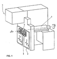
- FIG. 1 represents an example of a machine tool 1 of this type.
- these machines comprise a doll 4 and a barrel 5.
- a motor (not shown) drives the doll and the cannon in rotation (in the figure, the axis of rotation corresponds to the axis "z").
- the part or blank to be machined is fixed in the axis of rotation by clamps.
- the material to be machined may be in the form of a long bar held in the axis "z" of the cannon by bar clamping means.
- the machine tool 1 works one end of the bar and the doll 4 comprises bar feed means, which are provided to control the position of the bar along the axis "z".
- the machine tool 1 also comprises a "yx axis system” 2 designed to receive at least one machining tool 3. This tool may be, for example, a knife or a cutting tool.
- the axis system 2 is provided to be movable in a plane “xy” perpendicular to the axis of rotation "z". The displacement in the plane "xy” makes it possible to bring the tool 3 into the working position in contact with the workpiece and possibly to switch from one tool to another when the axis system "yx" 2 in several door.
- the "yx" 2 axis system is usually not designed to turn on itself. Consequently, the movements of the axis system 2, and therefore of the tool 3, are only translational movements (the tool always remains oriented in the same direction).
- the machine tool 1 must naturally also allow movement along the axis "z" of the tool relative to the workpiece. This displacement can, possibly, be obtained by moving the axis system 2 itself. However, most often, it is the workpiece that is moved along its axis "z” by the doll using its bar feed means. These movements along three axes "x, y, z" are controlled either manually or automatically.
- the movements of the "yx" axis system 2 can be controlled by numerically programmable electronic control means.
- the present invention relates to the latter type of machine tools, called numerical control, in which the movements along the three axes "x, y, z" are controlled by programmable electronic control means.
- a machine tool designed to work on a rotating part can generally only machine parts with concentric and coaxial cylindrical or conical spans, that is to say that the main axes of the various The staves are all aligned on a main longitudinal axis.
- a workpiece 11 provided with one or more bearing surfaces (referenced 12 and 13 in FIG. 2) eccentric to each other, it is normally necessary to stop the machine between the machining of the various bearing surfaces, to offset the workpiece in the spindle of the workpiece spindle and resume machining for the next eccentric scope.
- This requires many manipulations difficult to achieve by automatic means. Thus, such manipulations have a negative effect on machining precision as well as on the rate of work.
- said method is furthermore provided for operating a specially constructed machining machine and not a numerically controlled machining machine of known type whose tools only move in translation.
- the device described in this second document comprises means for moving the tool that allow movements of this tool in a plane (xy) perpendicular to the axis of rotation of the piece, but these means do not allow translational movements in each of the orthogonal directions.
- the displacements in the plane perpendicular to the axis of rotation of the part are displacements according to arcs of circles.
- the device of this third document comprises means for keeping a part in constant rotation about an axis, a tool mounted on a system of axes allowing displacements in perpendicular directions (X, Y) in a perpendicular plane (xy) to the axis of rotation, programmable control means for controlling the axis system according to the angular position of the part on its axis of rotation.
- the machining is performed by means of a rotary tool and it is the support of this rotary tool which is moved on a circular path (around the axis of the scope that it realizes) in synchronism with the rotation of the part.
- the device of US-A-5,396,821 is a special construction and does not consist of a numerically controlled machining machine of known type whose tools only move in translation.
- this third device is essentially the rotation of the tool that causes the removal of chips and the risk of formation of facets is certainly less than in the case of the invention, because in the case of the pending application it is the movement of rotation of the part that causes the removal of chips.
- the present invention aims to overcome the disadvantages of the prior art, in particular by providing a method for machining a workpiece comprising at least one non-concentric surface without the need to shift the workpiece spindle by a determined value. before starting the machining of the non-concentric scope.
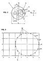
- the part 11 of Figure 2 comprises a first cylindrical surface 12 having a certain diameter (D).
- first bearing surface 12 On this first bearing surface 12, there is a second cylindrical bearing surface 13 whose diameter (d) is smaller than that of the first bearing surface and whose longitudinal axis is offset by a value ⁇ relative to the longitudinal axis of the bearing surface. 12.
- the bar or blank to become the part is kept rotating.
- the axis of rotation "z" of the machine tool does not necessarily correspond to the geometric axis of one of the cylindrical bearing surfaces to be machined.
- the part to be produced could also include one or more additional cylindrical bearing surfaces, all eccentric relative to each other.
- the rotation frequency of the tool will be the same as the rotation frequency of the part on itself.
- the programming mode for controlling the execution of the above trajectory will naturally depend on the particular model of machine tool used. Those skilled in the art will be able to choose a programming mode adapted to the specifications of the CNC machine tool at their disposal. It is however useful to specify that it is important that the trajectory of the tool is well synchronized with the angular displacement of the rotating part on itself. If one wants to be able to work at reasonably high speeds, this last constraint requires the use of a numerical control that is both fast and precise.
- EP0 474 603 and EP0 543 034 which generally relate to machine tools, both describe a control method for moving a tool relative to a rotated workpiece. Both methods are characterized by the fact that the movements of the tool relative to the workpiece along the three axes "x, y, z" are calculated by an external programming unit, even before machining the workpiece. This feature has the advantage of allowing a high speed of execution even with a hardware whose computing power is average.
- step tables The movements of the tool relative to the workpiece are previously programmed in the form of "step tables" ( Figure 5). To do this, the travel time is first cut into small successive time intervals of fixed duration. Since the movement of the tool must be synchronized with the rotation of the workpiece, the duration of the time intervals must be chosen so that a complete spindle revolution can be completed in an integer of these intervals. time. On the other hand, he It is also necessary that the number of intervals subdividing a turn is sufficient to define an adequate number of points on the trajectory of the tool.
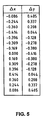
- FIG. 5 is a table whose two columns ⁇ x and ⁇ y respectively constitute "step tables" for the movements of the tool along the directions "x" and "y". These two tables each have 15 steps together defining the speed and direction of the tool along its circular path.
- Figure 5 gives step lengths in quite arbitrary units.
- the precision (the number of significant digits) is also arbitrary. Note that In practice, some numerically controlled machine tools make it possible to position the tool with a precision that can reach one-tenth of a micron.
- FIG. 3 gives the trajectory 16 corresponding to the pitch tables of FIG. 5.
- Each of the two axes of displacement of the tool is controlled separately by one of the pitch tables. Consequently, the resulting displacement of the tool 15 in the "xy" plane is theoretically performed by successive jumps along rectilinear segments 20, and the sequence of these rectilinear segments should produce a polygonal trajectory 16. If it were not corrected, this characteristic could constitute a crippling disadvantage.
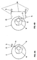
- FIG. 4 shows the example of a trajectory completed to include a stopping point (referenced 25) situated at a distance from the part.
- a stopping point referenced 25
- FIG. 4A in addition to the circular movement 16, there is shown a rectilinear linear input segment 26 corresponding to a movement of the knife 15 along the "y" axis from the stopping point to come into contact with the rotating part.
- Figure 4B shows a rectilinear segment 27 of "linear output” which also corresponds to a movement of the knife along the axis "y".
- the return to the stopping point is done by the path referenced 28.
- the passage through the stopping point 25 can be programmed at the end of each circular trajectory 16 of the tool 15, or less frequently according to the characteristics of the control system of the machine tool used.
- the “linear input” segment can, for example, be programmed in the form of a single step ⁇ y placed at the beginning of the sequence given in FIG. 5.
- the segment of "linear input” can be programmed as a single step ⁇ y placed at the beginning of the sequence given in FIG.
- linear output can also be programmed as a single ⁇ y step at the end of the same sequence.
- the return to the stopping point shown in FIG. 4B by the path referenced 28
- Providing a stopping point out of material may have other advantages in addition to that of preventing the risk, already mentioned, of desynchronization between the movement of the axis system "yx" and that of the rotating part. Indeed, the control software of a CNC machine tool is often provided to allow only a number of whole steps per spindle revolution. This precaution is known in the prior art to avoid problems when using the machine tool for combing operations. Due to rounding errors, this characteristic of the software sometimes leads to the control of a part revolution without movements of the "yx" axis system. However, if such immobilization of the "yx" axis system occurs during the execution of the method of the present invention, as already mentioned, it is desirable that the stopping point be located out of material.
- the operation is carried out either by removing chips in the direction of the "z" axis, either by removing chips in the direction of the "x" axis, or by a combination of these two directions. It will be understood that these different possibilities also exist when it comes to machining operations according to the method of the present invention.
- step tables to produce this trajectory in open loops based on the tables of Figure 5.
- the step table ⁇ y does not have to take it into account and, as in the previous example, it will consist essentially of several repetitions of the sequence of fifteen steps given in FIG. 5.
- the sequences of steps ⁇ x are obtained by adding at each step ⁇ x of FIG. 5, a constant quantity corresponding to the reduction of the radius X0 during the duration of a step.
- the part of which we have just described the machining comprises only cylindrical bearing surfaces whose axes are parallel.
- the method of the present invention also makes it possible, for example, to produce parts with eccentric conical bearing surfaces.
- to machine a conical bearing it suffices to operate as for a cylindrical bearing while taking into account the variation of the diameter "d" as the advance along the axis "z".
- the trajectory that the tool must traverse in the plane (xy) is not, either, a closed circular trajectory, but a trajectory consisting of a succession substantially circular open loops and constant radius.
- the "step tables" ⁇ x and ⁇ y to produce this trajectory in open loops can be obtained in a manner similar to that described for the previous example.
- the method of the present invention also makes it possible to produce spans whose axes are not parallel. Indeed, to machine such oblique bearing surfaces, it is sufficient to operate as for a parallel cylindrical bearing while taking into account the variation of the center distance " ⁇ " as the advance along the axis "z"". In the latter case, the trajectory that the tool must traverse in the plane (xy) is not, either, a circle but a spiral whose pitch depends on the variation of the center distance " ⁇ " as and when measuring the advance along the "z” axis.
- each step ⁇ x and ⁇ y is proportional to the center distance " ⁇ ".
- the method of the present invention is not limited to spans whose shape corresponds to one of the examples given above.
- Those skilled in the art will know how to determine the hourly equation of the tool in order to obtain other shapes of non-concentric bearing parts.
- the present invention does not limit this to spans of circular section. Indeed, by slightly changing the hourly equation of the tool to obtain, for example, an elliptical trajectory, it is possible to machine in particular eccentric ranges whose section is elliptical.
Landscapes
- Engineering & Computer Science (AREA)
- Human Computer Interaction (AREA)
- Manufacturing & Machinery (AREA)
- Physics & Mathematics (AREA)
- General Physics & Mathematics (AREA)
- Automation & Control Theory (AREA)
- Numerical Control (AREA)
- Turning (AREA)
Description
La présente invention concerne généralement les machines-outils (notamment les tours) qui sont conçues pour travailler sur une pièce maintenue en rotation, et qui comportent des moyens électroniques programmables commandant un système d'axes permettant le déplacement d'un outil dans le plan perpendiculaire à l'axe de rotation de la pièce. La présente invention concerne plus particulièrement un procédé pour usiner des pièces comportant des portées non-coaxiales ou non-concentriques avec une machine-outil telle que décrite ci-dessus. La présente invention concerne, également, les machines-outils qui sont programmées pour mettre en oeuvre le procédé de la présente invention.The present invention generally relates to machine tools (especially lathes) which are designed to work on a part held in rotation, and which comprise programmable electronic means controlling a system of axes allowing the movement of a tool in the perpendicular plane to the axis of rotation of the part. The present invention more particularly relates to a method for machining parts with non-coaxial or non-concentric spans with a machine tool as described above. The present invention also relates to machine tools which are programmed to implement the method of the present invention.
On connaît un grand nombre de machines-outils conçues pour travailler sur une pièce maintenue en rotation. On utilise le plus souvent ces machines-outils pour des opérations de tournage ou d'alésage ou encore pour tronçonner, percer, fraiser, tourbillonner, polygonner, etc. La figure 1 représente un exemple de machine-outil 1 de ce type. Habituellement, ces machines comportent une poupée 4 et un canon 5. Un moteur (non représenté) entraîne la poupée et le cannon en rotation (sur la figure, l'axe de rotation correspond à l'axe « z »). La pièce ou ébauche à usiner est fixée dans l'axe de rotation par des pinces. Dans le cas de tours automatiques, la matière à usiner peut se présenter sous la forme d'une longue barre maintenue dans l'axe « z » du cannon par des moyens de serrage de barre. Dans ce cas, la machine-outil 1 travaille une extrémité de la barre et la poupée 4 comporte des moyens d'alimentation de barre, qui sont prévus pour commander la position de la barre selon l'axe « z ». La machine-outil 1 comporte aussi un « système d'axes y-x » 2 prévu pour recevoir au moins un outil d'usinage 3. Cet outil peut être, par exemple, un couteau ou un outil à tronçonner. Le système d'axes 2 est prévu pour être déplaçable dans un plan « xy » perpendiculaire à l'axe de rotation « z ». Le déplacement dans le plan « xy » permet d'amener l'outil 3 en position de travail en contact avec la pièce à usiner et, éventuellement, de passer d'un outil à l'autre lorsque le système d'axes « y-x » 2 en porte plusieurs. Pendant la coupe, l'outil est maintenu en contact avec la pièce et c'est le mouvement de rotation de celle-ci qui provoque l'enlevage de copeaux. Le système d'axes « y-x » 2 n'est habituellement pas prévu pour tourner sur lui-même. En conséquence, les mouvements du système d'axes 2, et donc de l'outil 3, sont uniquement des mouvements de translation (l'outil reste toujours orienté dans la même direction). La machine-outil 1 doit naturellement aussi permettre un déplacement selon l'axe « z » de l'outil relativement à la pièce à usiner. Ce déplacement peut, éventuellement, être obtenu par déplacement du système d'axes 2 lui-même. Toutefois, le plus souvent, c'est la pièce à usiner qui est déplacée le long de son axe « z » par la poupée à l'aide de ses moyens d'alimentation de barre. Ces déplacements selon trois axes « x,y,z » sont commandés soit manuellement soit automatiquement. Dans ce dernier cas, les mouvements du système d'axes « y-x » 2 peuvent être asservis à des moyens électroniques de commande programmables numériquement. La présente invention concerne ce dernier type de machines-outils, dites à commande numérique, dans lesquelles les déplacements selon les trois axes « x,y,z » sont asservis à des moyens électroniques de commande programmables.A large number of machine tools are known for working on a part held in rotation. These machine tools are most often used for turning or boring operations or for cutting, drilling, milling, swirling, polygoning, etc. FIG. 1 represents an example of a
Une machine-outil conçue pour travailler sur une pièce en rotation (tournage, alésage, etc.) ne peut généralement usiner que des pièces ayant des portées cylindriques ou coniques concentriques et coaxiales, c'est-à-dire que les axes principaux des diverses portées sont tous alignés sur un axe longitudinal principal. Lorsqu'on désire usiner une pièce 11 munie d'une ou plusieurs portées (référencées 12 et 13 sur la figure 2) excentrées entre elles, il est normalement nécessaire d'arrêter la machine entre l'usinage des diverses portées, de décaler pièce dans la pince de la broche porte-pièce et de reprendre l'usinage pour la portée excentrée suivante. Ceci nécessite de nombreuses manipulations difficiles à réaliser par des moyens automatiques. Ainsi, de telles manipulations influent négativement sur la précision d'usinage, de même que sur la cadence de travail.A machine tool designed to work on a rotating part (turning, boring, etc.) can generally only machine parts with concentric and coaxial cylindrical or conical spans, that is to say that the main axes of the various The staves are all aligned on a main longitudinal axis. When it is desired to machine a
L'existence des difficultés précitées a assurément engendré l'élaboration de techniques particulières pour la réalisation d'usinages spéciaux pendant la rotation de la pièce autour d'un axe de rotation.The existence of the aforementioned difficulties has certainly led to the development of special techniques for performing special machining during the rotation of the part about an axis of rotation.
Parmi ces techniques particulières, d'un premier document US-A-5,467,675 de l'état de la technique, on connaît un dispositif d'usinage et un procédé de commande de ce dispositif qui sont conçus pour la réalisation, sur une pièce entraînée en rotation, de surfaces incurvées, notamment concaves.Among these particular techniques, a first US-A-5,467,675 of the state of the art, there is known a machining device and a control method of this device which are designed for the realization, on a part driven by rotation, curved surfaces, in particular concave.
En ce qui concerne le procédé décrit dans ce premier document, outre qu'il n'est pas prévu pour réaliser des surfaces cylindriques ou coniques dont l'axe longitudinal est décalé d'une certaine distance par rapport à l'axe longitudinal de rotation de la pièce, ledit procédé est de surcroît prévu pour faire fonctionner une machine d'usinage spécialement construite et non une machine de décolletage à commande numérique de type connu dont les outils ne se déplacent qu'en translation.As regards the method described in this first document, besides it is not intended to provide cylindrical or conical surfaces whose longitudinal axis is offset by a certain distance from the longitudinal axis of rotation of the workpiece, said method is furthermore provided for operating a specially constructed machining machine and not a numerically controlled machining machine of known type whose tools only move in translation.
Pour ce qui est du dispositif décrit dans ledit premier document :
- il comprend, certes, classiquement des moyens de déplacement de l'outil qui autorisent des déplacements en translation de cet outil dans des directions perpendiculaires (X, Y) situées dans un plan (xy) perpendiculaire à l'axe de rotation (Z) de la pièce, mais
- il requiert la mise en oeuvre des moyens de contrôle de la position de l'outil d'usinage (laser, interféromètre) qui sont extrêmement onéreux.
- it comprises, of course, conventionally means for moving the tool which allow displacement in translation of the tool in perpendicular directions (X, Y) located in a plane (xy) perpendicular to the axis of rotation (Z) of the room but
- it requires the implementation of the control means of the position of the machining tool (laser, interferometer) which are extremely expensive.
Quant aux surfaces obtenues par la mise en oeuvre de la technique de ce premier document, elles doivent subir un usinage de finition.As for the surfaces obtained by the implementation of the technique of this first document, they must undergo finishing machining.
D'un second document US-A-5,309,800 de l'état de la technique, on connaît un dispositif et un procédé qui sont conçus pour la réalisation, sur une pièce entraînée en rotation, d'une.surface cylindrique sensiblement elliptique, dont l'axe longitudinal est coaxial à celui de la pièce.From a second document US-A-5,309,800 of the state of the art, there is known a device and a method which are designed for the realization, on a part driven in rotation, of a substantially elliptical cylindrical surface, of which longitudinal axis is coaxial with that of the workpiece.
Pour ce qui est du dispositif décrit dans ce second document, il comprend des moyens de déplacement de l'outil qui autorisent des déplacements de cet outil dans un plan (xy) perpendiculaire à l'axe de rotation de la pièce, mais ces moyens n'autorisent cependant pas des déplacements en translation dans chacune des directions orthogonales.As regards the device described in this second document, it comprises means for moving the tool that allow movements of this tool in a plane (xy) perpendicular to the axis of rotation of the piece, but these means do not allow translational movements in each of the orthogonal directions.
En effet, les déplacements dans le plan perpendiculaire à l'axe de rotation de la pièce sont des déplacements selon des arcs de cercles.Indeed, the displacements in the plane perpendicular to the axis of rotation of the part are displacements according to arcs of circles.
En ce qui concerne le procédé de ce second document, il n'est pas non plus prévu pour réaliser des surfaces cylindriques ou coniques dont l'axe longitudinal est décalé d'une certaine distance par rapport à l'axe longitudinal de rotation de la pièce.Regarding the method of this second document, it is not intended to provide cylindrical or conical surfaces whose longitudinal axis is offset by a certain distance from the longitudinal axis of rotation of the workpiece .
Quant aux surfaces obtenues par la mise en oeuvre de la technique de ce second document, elles doivent également subir un usinage de finition.As for the surfaces obtained by the implementation of the technique of this second document, they must also undergo finishing machining.
D'un troisième document US-A-5,396,821, on connaît un dispositif et un procédé qui sont conçus pour, sur une pièce entraînée en rotation selon l'axe longitudinal d'une première portée, permettre l'usinage d'au moins une seconde portée dont l'axe longitudinal est décalé d'une certaine distance par rapport à l'axe longitudinal de la première portée, ladite portée comportant un axe de symétrie de révolution.From a third document US-A-5,396,821, there is known a device and a method which are designed for, on a part driven in rotation along the longitudinal axis of a first scope, allow the machining of at least one second range whose longitudinal axis is offset by a certain distance from the longitudinal axis of the first range, said bearing having an axis of symmetry of revolution.
Le dispositif de ce troisième document comprend des moyens pour maintenir une pièce en rotation constante autour d'un axe, un outil monté sur un système d'axes permettant des déplacements selon des directions perpendiculaires (X, Y) dans un plan (xy) perpendiculaire à l'axe de rotation, des moyens de commandes programmables pour commander le système d'axes en fonction de la position angulaire de la pièce sur son axe de rotation.The device of this third document comprises means for keeping a part in constant rotation about an axis, a tool mounted on a system of axes allowing displacements in perpendicular directions (X, Y) in a perpendicular plane (xy) to the axis of rotation, programmable control means for controlling the axis system according to the angular position of the part on its axis of rotation.
Cependant, avec le dispositif et le procédé d'usinage de ce troisième document, l'usinage est réalisé au moyen d'un outil rotatif et le c'est le support de cet outil rotatif qui est déplacé sur une trajectoire circulaire (autour de l'axe de la portée qu'il réalise) en synchronisme avec la rotation de la pièce.However, with the device and the machining method of this third document, the machining is performed by means of a rotary tool and it is the support of this rotary tool which is moved on a circular path (around the axis of the scope that it realizes) in synchronism with the rotation of the part.
Le dispositif du document US-A-5,396,821 est une construction spéciale et ne consiste pas en une machine de décolletage à commande numérique de type connu dont les outils ne se déplacent qu'en translation.The device of US-A-5,396,821 is a special construction and does not consist of a numerically controlled machining machine of known type whose tools only move in translation.
Avec ce troisième dispositif, c'est essentiellement la rotation de l'outil qui provoque l'enlevage de copeaux et le risque de formation de facettes est assurément moindre que dans le cas de l'invention, car dans le cas de la demande en instance, c'est le mouvement da rotation da la pièce qui provoque l'enlevage de copeaux.With this third device, it is essentially the rotation of the tool that causes the removal of chips and the risk of formation of facets is certainly less than in the case of the invention, because in the case of the pending application it is the movement of rotation of the part that causes the removal of chips.
Ces techniques particulières d'usinage ont leurs avantages, mais, tel que cela a été exprimé plus avant, l'invention vise à l'utilisation d'une machine traditionnelle de décolletage à commande numérique pour l'usinage d'une portée cylindrique ou conique, décalée par rapport à l'axe de rotation d'une extrémité de barre qui la porte, et ce :
- sans recourir à un montage particulier de la pièce dans la pince de la broche porte pièce, et
- en surmontant la réserve qu'un homme du métier peut avoir à utiliser une machine traditionnelle de décolletage programmable pour la réalisation d'une telle surface, du fait que le déplacement d'un outil par pas s'effectue théoriquement par sauts successifs, selon des segments rectilignes, qui devraient produire une trajectoire polygonale.
- without resorting to a particular assembly of the workpiece in the clip of the workpiece spindle, and
- by overcoming the reserve that a person skilled in the art may have to use a traditional machining machine programmable for the realization of such a surface, because the movement of a tool step is theoretically made by successive jumps, according to rectilinear segments, which should produce a polygonal trajectory.
La présente invention vise à remédier aux inconvénients de l'art antérieur, notamment, en fournissant un procédé pour usiner une pièce comportant au moins une portée non-concentrique sans qu'il soit nécessaire de décaler la broche porte-pièce d'une valeur déterminée avant de commencer l'usinage de la portée non-concentrique.The present invention aims to overcome the disadvantages of the prior art, in particular by providing a method for machining a workpiece comprising at least one non-concentric surface without the need to shift the workpiece spindle by a determined value. before starting the machining of the non-concentric scope.
Un tel procédé, répondant au but mentionné ainsi qu'à d'autres buts encore, et possédant encore d'autres avantages est conforme à la revendication 1.Such a process, fulfilling the stated purpose as well as other purposes, and still having other advantages, is in accordance with
La description qui suit concerne une forme particulière de réalisation de la présente invention. L'homme du métier saura adapter le procédé décrit à d'autres machines-outils et à d'autres formes de pièces à usiner. Cette description est à considérer en regard des dessins annexés dans lesquels :
- la figure 1 représente un exemple d'une machine-outil, en l'occurrence, une machine de décolletage susceptible d'être utilisée pour mettre en oeuvre le procédé de la présente invention;
- la figure 2 représente un exemple d'une pièce réalisable avec le procédé de la présente invention. Elle montre aussi la trajectoire effectuée par l'outil selon le procédé d'usinage de la présente invention;
- la figure 3 montre un exemple de trajectoire de l'outil de coupe programmée en mode pas-à-pas;
- la figure 4A montre un exemple de trajectoire « d'entrée linéaire » de l'outil de coupe; et la figure 4B un exemple de trajectoire de « sortie linéaire » de l'outil de coupe;
- la figure 5 montre les données contenues dans les « tables de pas » pour faire exécuter à l'outil la trajectoire représentée à la figure 3.
- FIG. 1 represents an example of a machine tool, in this case a free-cutting machine that can be used to implement the method of the present invention;
- Figure 2 shows an example of a workable part with the method of the present invention. It also shows the path performed by the tool according to the machining method of the present invention;
- FIG. 3 shows an example of a trajectory of the cutting tool programmed in step-by-step mode;
- FIG. 4A shows an example of a "linear input" trajectory of the cutting tool; and FIG. 4B an example of a "linear output" trajectory of the cutting tool;
- FIG. 5 shows the data contained in the "step tables" to make the tool execute the trajectory represented in FIG.
La pièce 11 de la figure 2 comprend une première portée cylindrique 12 ayant un certain diamètre (D). Sur cette première portée 12, on a une deuxième portée cylindrique 13 dont le diamètre (d) est inférieur à celui de la première portée et dont l'axe longitudinal est décalé d'une valeur δ par rapport à l'axe longitudinal de la portée 12.The
Pour réaliser cette pièce avec le procédé de la présente invention, la barre ou l'ébauche destinée à devenir la pièce est maintenue en rotation. L'axe de rotation « z » de la machine-outil ne correspond pas nécessairement à l'axe géométrique d'une des portées cylindriques à usiner. La pièce à réaliser pourrait d'ailleurs comporter une ou plusieurs portées cylindriques supplémentaires, toutes excentrées les unes par rapport aux autres.To achieve this part with the method of the present invention, the bar or blank to become the part is kept rotating. The axis of rotation "z" of the machine tool does not necessarily correspond to the geometric axis of one of the cylindrical bearing surfaces to be machined. The part to be produced could also include one or more additional cylindrical bearing surfaces, all eccentric relative to each other.
A titre d'exemple de mise en oeuvre du procédé de la présente invention, nous nous limiterons au cas où la portée cylindrique 12 est réalisée coaxialement à l'axe de rotation. Dans ces conditions, le centre 14 de la portée cylindrique excentrée 13 parcourt un cercle de rayon « δ » autour de l'axe de rotation « Oz ». Comme on l'a déjà dit, selon la présente invention, l'outil de coupe 3 (figure 1) ne se déplace qu'en translation. De plus, l'angle d'attaque de l'outil par rapport à la pièce 11 demeure de préférence (mais pas nécessairement) constant. Dans ces conditions, la pointe 15 de l'outil doit parcourir une trajectoire circulaire 16 pour suivre la rotation du centre 14 autour de l'axe « Oz ». Puisque la pointe 15 de l'outil demeure en contact avec la surface de la portée cylindrique 13, la trajectoire 16 du couteau dans le plan « xy » sera décentrée d'une distance d/2 par rapport à l'axe de rotation « Oz ». Si l'attaque se fait de face, le décalage de valeur XO = d/2 se fera selon l'axe « x ».As an example of implementation of the method of the present invention, we will limit to the case where the
L'équation générale du mouvement de l'outil pour usiner une portée cylindrique 13 non-concentrique sera donc : ![]()
![]()
De plus, la fréquence de rotation de l'outil sera la même que la fréquence de rotation de la pièce sur elle-même. Dans le cas habituel d'une machine-outil faisant tourner la pièce à vitesse constante, nous pouvons écrire l'équation horaire du mouvement du système d'axes « y-x » et donc de l'outil: ![]()
![]()

n est la vitesse de rotation en tours/minute.In addition, the rotation frequency of the tool will be the same as the rotation frequency of the part on itself. In the usual case of a machine tool rotating the workpiece at a constant speed, we can write the time equation of the movement of the "yx" axis system and thus of the tool: ![]()
![]()
n is the speed of rotation in revolutions / minute.
Le mode de programmation pour commander l'exécution de la trajectoire ci-dessus dépendra naturellement du modèle particulier de machine-outil utilisé. L'homme du métier saura choisir un mode de programmation adapté aux spécifications de la machine-outil à commande numérique dont il dispose. Il est toutefois utile de préciser qu'il est important que la trajectoire de l'outil soit bien synchronisée avec le déplacement angulaire de la pièce tournant sur elle-même. Si l'on veut pouvoir travailler à des vitesses raisonablement élevées, cette dernière contrainte impose l'utilisation d'une commande numérique à la fois rapide et précise.The programming mode for controlling the execution of the above trajectory will naturally depend on the particular model of machine tool used. Those skilled in the art will be able to choose a programming mode adapted to the specifications of the CNC machine tool at their disposal. It is however useful to specify that it is important that the trajectory of the tool is well synchronized with the angular displacement of the rotating part on itself. If one wants to be able to work at reasonably high speeds, this last constraint requires the use of a numerical control that is both fast and precise.
Les documents EP0 474 603 et EP0 543 034 qui concernent généralement les machines-outils, décrivent tous deux un procédés de commande pour déplacer un outil par rapport à une pièce maintenue en rotation. Ces procédés se caractérisent tous deux par le fait que les déplacements de l'outil par rapport à la pièce selon les trois axes « x,y,z » sont calculés par une unité de programmation externe, avant même l'usinage de la pièce. Cette particularité présente l'avantage de permettre une vitesse d'exécution élevée même avec un matériel dont la puissance de calcul est moyenne.EP0 474 603 and EP0 543 034, which generally relate to machine tools, both describe a control method for moving a tool relative to a rotated workpiece. Both methods are characterized by the fact that the movements of the tool relative to the workpiece along the three axes "x, y, z" are calculated by an external programming unit, even before machining the workpiece. This feature has the advantage of allowing a high speed of execution even with a hardware whose computing power is average.
La suite du présent exemple de mise en oeuvre du procédé de la présente invention sera donnée en faisant référence aux enseignements des deux documents susmentionnés. Toutefois, il est claire que la présente invention ne se limite pas à ce mode particulier de programmation des déplacements de l'outil et que l'homme du métier pourra choisir un autre mode de programmation sans sortir du cadre de la revendication 1.The following of the present example of implementation of the method of the present invention will be given with reference to the teachings of the two aforementioned documents. However, it is clear that the present invention is not limited to this particular mode of programming the movements of the tool and that the skilled person can choose another programming mode without departing from the scope of
Les déplacements de l'outils par rapport à la pièce à usiner sont préalablement programmés sous la forme de « tables des pas » (figure 5). Pour ce faire, le temps de déplacement est tout d'abord découpé en petits intervalles de temps successifs de durée fixe. Comme le déplacement de l'outil doit être synchronisé à la rotation de la pièce à usiner, il faut choisir la durée des intervalles de temps de façon à permettre l'accomplissement d'un tour de broche complet en un nombre entier de ces intervalles de temps. D'autre part, il faut également que le nombre d'intervalles subdivisant un tour soit suffisant pour définir un nombre adéquat de points sur la trajectoire de l'outil.The movements of the tool relative to the workpiece are previously programmed in the form of "step tables" (Figure 5). To do this, the travel time is first cut into small successive time intervals of fixed duration. Since the movement of the tool must be synchronized with the rotation of the workpiece, the duration of the time intervals must be chosen so that a complete spindle revolution can be completed in an integer of these intervals. time. On the other hand, he It is also necessary that the number of intervals subdividing a turn is sufficient to define an adequate number of points on the trajectory of the tool.
Pour donner une idée des ordres de grandeur, nous donnons à titre d'exemple les valeurs suivantes :
- durée d'un pas TE = 0,008 secondes;
- n = 500 tours/minute;
- nombre de pas par tour N = 15.
- duration of one step TE = 0.008 seconds;
- n = 500 rpm;
- number of steps per turn N = 15.
De manière générale, pour un déplacement par pas de durée constante, l'équation horaire, pour j = 1,..,N, peut s'écrire : ![]()
![]()
avec j = partie entière de t/TEIn a general way, for a displacement by step of constant duration, the hourly equation, for j = 1, .., N, can be written: ![]()
![]()
with j = integer part of t / TE
A partir de l'équation horaire ci-dessus, il est facile de calculer une « tables des pas » pour chacune des directions de déplacement « x » et « y ». Si l'on désigne par Δx la longueur d'un pas dans la direction « x » et par Δy la longueur d'un pas dans la direction « y », on a :![]()
![]()
![]()
![]()
La figure 5 annexée est un tableau dont les deux colonnes Δx et Δy constituent respectivement des « tables des pas » pour les déplacements de l'outil selon les directions « x » et « y ». Ces deux tables comportent chacune 15 pas définissant conjointement la vitesse et la direction de l'outil le long de sa trajectoire circulaire. Comme il s'agit d'un exemple, la figure 5 donne les longueurs des pas dans des unités tout à fait arbitraires. De même, la précision (le nombre de chiffres significatifs) est arbitraire également. Signalons qu'en pratique, certaines machines-outils à commande numérique permettent de positionner l'outil avec une précision qui peut atteindre le dixième de micron.The appended FIG. 5 is a table whose two columns Δx and Δy respectively constitute "step tables" for the movements of the tool along the directions "x" and "y". These two tables each have 15 steps together defining the speed and direction of the tool along its circular path. As this is an example, Figure 5 gives step lengths in quite arbitrary units. Similarly, the precision (the number of significant digits) is also arbitrary. Note that In practice, some numerically controlled machine tools make it possible to position the tool with a precision that can reach one-tenth of a micron.
L'exemple de la figure 5 correspond à un déplacement de l'outil sur 15 pas. Toutefois, dans un cas pratique les « tables des pas » comprennent normalement un plus grand nombre de pas. Précisons, en particulier, que si l'outil accomplit plusieurs fois la trajectoire circulaire donnée par l'équation horaire ci-dessus, les « tables des pas » Δx et Δy contiendront plusieurs répétitions de la séquence de 15 pas donnée à la figure 5.The example of Figure 5 corresponds to a movement of the tool on 15 steps. However, in a practical case the "step tables" normally include a greater number of steps. In particular, note that if the tool completes the circular trajectory given by the above time equation several times, the "step tables" Δx and Δy will contain several repetitions of the sequence of 15 steps given in FIG.
La figure 3 donne la trajectoire 16 correspondant aux tables des pas de la figure 5. Chacun des deux axes déplacement de l'outil est commandé séparément par l'une des tables de pas. En conséquence, le déplacement résultant de l'outil 15 dans le plan « xy » s'effectue théoriquement par sauts successifs selon des segments rectilignes 20, et l'enchaînement de ces segments rectilignes devrait produire une trajectoire 16 polygonale. Si elle n'était pas corrigée, cette caractéristique pourrait constituer un inconvénient rédhibitoire. Toutefois, de façon assez remarquable, dans la réalité, l'inertie mécanique du système a tendance, tout à la fois, à arrondir la trajectoire et à uniformiser la vitesse du mouvement. Ce qui remédie à l'inconvénient susmentionné. Grâce à cette caractéristique avantageuse, on peut même, dans bon nombre de cas, obtenir un lissage suffisant en se contentant de N = 8 pas par tour, le fait de réduire le nombre de pas présente l'avantage d'autoriser une plus grande vitesse de rotation de la broche.FIG. 3 gives the
Si on a recours à un mode de programmation du système d'axes « y-x » qui ne comporte pas de contrôle rétroactif systématique de la position effective du système d'axes, il existe un risque de désynchronisation entre le mouvement du système d'axes « y-x » 2 et celui de la pièce 11. Pour éviter cet inconvénient, il est possible de prévoir, à intervalles réguliers, des arrêts pendant lesquels s'effectuent un tour de broche 5 sans mouvement du système d'axes 2. Ces arrêts permettent au système d'axes d'attendre un signal indiquant le début du tour suivant de façon à repartir de façon bien synchronisée.If a programming mode of the "yx" axis system is used which does not have systematic feedback control of the actual position of the axis system, there is a risk of desynchronization between the movement of the axis system " yx »2 and that of the
Le fait de programmer des arrêts impose une contrainte. Il s'agit du fait que, pour ne pas avoir de cassure dans la courbe, le point d'arrêt du couteau doit être hors matière. La figure 4 montre l'exemple d'une trajectoire complétée pour comporter un point d'arrêt (référencé 25) situé à distance de la pièce. A la figure 4A, en plus du mouvement circulaire 16, on a représenté un segment rectiligne 26 « d'entrée linéaire » correspondant à un déplacement du couteau 15 selon l'axe « y » depuis le point d'arrêt pour venir en contact avec la pièce en rotation.Scheduling stops imposes a constraint. This is the fact that, in order not to have a break in the curve, the stopping point of the knife must be out of material. FIG. 4 shows the example of a trajectory completed to include a stopping point (referenced 25) situated at a distance from the part. In FIG. 4A, in addition to the
La figure 4B montre un segment rectiligne 27 de « sortie linéaire » qui correspond également à un déplacement du couteau selon l'axe « y ». Après la sortie, le retour au point d'arrêt se fait par le chemin référencé 28. Le passage par le point d'arrêt 25 pourra être programmé à la fin de chaque trajectoire circulaire 16 de l'outil 15, ou moins fréquemment selon les caractéristiques du système de commande de la machine-outil utilisée.Figure 4B shows a
Dans les « tables des pas » le segment « d'entrée linéaire » peut, par exemple, être programmé sous la forme d'un unique pas Δy placé au début de la séquence donnée à la figure 5. De même, le segment de « sortie linéaire » peut également être programmé sous la forme d'un pas Δy unique placé à la fin de la même séquence. Après la sortie linéaire, le retour au point d'arrêt (représenté sur la figure 4B par le chemin référencé 28) peut également être programmé sous la forme d'une suite de pas.In the "step tables" the "linear input" segment can, for example, be programmed in the form of a single step Δy placed at the beginning of the sequence given in FIG. 5. Similarly, the segment of "linear input" can be programmed as a single step Δy placed at the beginning of the sequence given in FIG. linear output "can also be programmed as a single Δy step at the end of the same sequence. After the linear output, the return to the stopping point (shown in FIG. 4B by the path referenced 28) can also be programmed as a sequence of steps.
Le fait de prévoir un point d'arrêt hors matière peut présenter d'autres avantages en plus de celui de prévenir le risque, déjà mentionné, de désynchronisation entre le mouvement du système d'axes « y-x » et celui de la pièce en rotation. En effet, les logiciels de commande d'une machine-outil à commande numérique sont souvent prévus pour n'autoriser qu'un nombre de pas entier par tour de broche. Cette précaution est connue dans l'art antérieur pour éviter des problèmes lors de l'utilisation de la machine-outil pour des opérations de peignages. En raison d'erreurs d'arrondi, cette caractéristique du logiciel entraîne parfois la commande d'un tour de la pièce sans mouvements du système d'axes « y-x ». Or, si une telle immobilisation du système d'axes « y-x » se produit durant l'exécution du procédé de la présente invention, comme on l'a déjà dit, il est souhaitable que le point d'arrêt soit situé hors matière.Providing a stopping point out of material may have other advantages in addition to that of preventing the risk, already mentioned, of desynchronization between the movement of the axis system "yx" and that of the rotating part. Indeed, the control software of a CNC machine tool is often provided to allow only a number of whole steps per spindle revolution. This precaution is known in the prior art to avoid problems when using the machine tool for combing operations. Due to rounding errors, this characteristic of the software sometimes leads to the control of a part revolution without movements of the "yx" axis system. However, if such immobilization of the "yx" axis system occurs during the execution of the method of the present invention, as already mentioned, it is desirable that the stopping point be located out of material.
Comme l'homme du métier le sait bien, dans les opérations d'usinage à l'aide de machines-outils du type concerné par la présente invention, on opère soit par enlevage de copeaux dans la direction de l'axe « z », soit par enlevage de copeaux dans la direction de l'axe « x », ou encore, par une combinaison de ces deux directions. On comprendra que ces différentes possibilités existent aussi quand il s'agit d'opérations d'usinage selon le procédé de la présente invention.As those skilled in the art are well aware, in machining operations using machine tools of the type concerned by the present invention, the operation is carried out either by removing chips in the direction of the "z" axis, either by removing chips in the direction of the "x" axis, or by a combination of these two directions. It will be understood that these different possibilities also exist when it comes to machining operations according to the method of the present invention.
Si l'enlevage de copeaux, et donc « l'avance », se fait dans la direction de l'axe « z », on comprendra que celle-ci n'influence pas le mouvement de l'outil dans le plan « xy ». Dans ces conditions, les « tables des pas » Δx et Δy n'ont pas à tenir compte explicitement de l'avance. Lorsqu'au contraire, on travaille avec une « avance » dans la direction de l'axe « x », le diamètre de la portée à usiner change progressivement. Or, comme on l'a vu, le rayon de la portée à usiner apparaît dans l'équation horaire du mouvement de l'outil. En effet : ![]()
![]()
Avec la pièce représentée sur la figure 2, on peut se convaincre que « XO », le rayon effectif de la pièce pour l'outil, passe de la valeur (d/2 + D/2) au début de l'opération d'usinage, à la valeur (d/2) à la fin de cette opération. Comme l'avance n'influence que le rayon de la pièce, et donc le paramètre « XO », il est relativement aisé de tenir compte de cette avance en programmant une réduction progressive de la valeur de « XO » sur un certain nombre de tours. La conséquence de cette réduction progressive de la valeur de « X0 » est que la trajectoire que doit parcourir l'outil dans le plan (xy) n'est pas une trajectoire circulaire fermée comme celle de l'équation horaire donnée plus haut. Au contraire dans le cas présent, la trajectoire de l'outil dans le plan (xy) est plus précisément une trajectoire constituée d'une succession de boucles ouvertes sensiblement circulaires et de rayon constant.With the part shown in FIG. 2, it can be convinced that "XO", the effective radius of the workpiece for the tool, goes from the value (d / 2 + D / 2) to the beginning of the operation of machining, to the value (d / 2) at the end of this operation. As the feed only influences the radius of the part, and therefore the parameter "XO", it is relatively easy to take this advance into account by programming a progressive reduction of the value of "XO" over a certain number of laps. . The consequence of this progressive reduction of the value of "X0" is that the trajectory that the tool must traverse in the plane (xy) is not a closed circular trajectory like that of the equation given above. On the contrary, in the present case, the trajectory of the tool in the plane (xy) is more precisely a trajectory consisting of a succession of substantially circular open loops of constant radius.
On peut définir des « tables des pas » pour produire cette trajectoire en boucles ouvertes en se basant sur les tables de la figure 5. Comme le rayon X0 n'entre que dans l'équation pour la direction « x », la table des pas Δy n'a pas à en tenir compte et, comme dans l'exemple précédent, elle sera constituée essentiellement de plusieurs répétitions de la séquence de quinze pas donnée à la figure 5. Les séquences de pas Δx, en revanche, sont obtenues en ajoutant, à chaque pas Δx de la figure 5, une quantité constante correspondant à la réduction du rayon X0 durant la durée d'un pas.We can define "step tables" to produce this trajectory in open loops based on the tables of Figure 5. As the X0 ray enters only in the equation for the direction "x", the step table Δy does not have to take it into account and, as in the previous example, it will consist essentially of several repetitions of the sequence of fifteen steps given in FIG. 5. The sequences of steps Δx, on the other hand, are obtained by adding at each step Δx of FIG. 5, a constant quantity corresponding to the reduction of the radius X0 during the duration of a step.
La pièce dont nous venons de décrire l'usinage comporte uniquement des portées cylindriques dont les axes sont parallèles. L'homme du métier comprendra que le procédé de la présente invention permet également de produire, par exemple, des pièces avec des portées coniques excentrées. En effet, pour usiner une portée conique, il suffit d'opérer comme pour une portée cylindrique tout en tenant compte de la variation du diamètre « d » au fur et à mesure de l'avance selon l'axe « z ». Ainsi, de façon semblable à ce qui est expliqué dans le paragraphe précédent, la trajectoire que doit parcourir l'outil dans le plan (xy) n'est pas, non plus, une trajectoire circulaire fermée, mais une trajectoire constituée d'une succession de boucles ouvertes sensiblement circulaires et de rayon constant. Les « tables des pas » Δx et Δy pour produire cette trajectoire en boucles ouvertes peuvent être obtenues de manière analogue à ce qui a été décrit pour l'exemple précédent.The part of which we have just described the machining comprises only cylindrical bearing surfaces whose axes are parallel. Those skilled in the art will understand that the method of the present invention also makes it possible, for example, to produce parts with eccentric conical bearing surfaces. Indeed, to machine a conical bearing, it suffices to operate as for a cylindrical bearing while taking into account the variation of the diameter "d" as the advance along the axis "z". Thus, similar to what is explained in the previous paragraph, the trajectory that the tool must traverse in the plane (xy) is not, either, a closed circular trajectory, but a trajectory consisting of a succession substantially circular open loops and constant radius. The "step tables" Δx and Δy to produce this trajectory in open loops can be obtained in a manner similar to that described for the previous example.
De même, l'homme du métier comprendra que le procédé de la présente invention permet également de produire des portées dont les axes ne sont pas parallèles. En effet, pour usiner de telles portées obliques, il suffit d'opérer comme pour une portée cylindrique parallèle tout en tenant compte de la variation de l'entraxe « δ » au fur et à mesure de l'avance selon l'axe « z ». Dans ce dernier cas, la trajectoire que l'outil doit parcourir dans le plan (xy) n'est pas, non plus, un cercle mais une spirale dont le pas dépend de la variation de l'entraxe « δ » au fur et à mesure de l'avance selon l'axe « z ».Likewise, those skilled in the art will understand that the method of the present invention also makes it possible to produce spans whose axes are not parallel. Indeed, to machine such oblique bearing surfaces, it is sufficient to operate as for a parallel cylindrical bearing while taking into account the variation of the center distance "δ" as the advance along the axis "z"". In the latter case, the trajectory that the tool must traverse in the plane (xy) is not, either, a circle but a spiral whose pitch depends on the variation of the center distance "δ" as and when measuring the advance along the "z" axis.
Comme on l'a vu plus haut avec l'équation horaire du mouvement, chaque pas Δx et Δy est proportionnel à l'entraxe « δ ». Ainsi, on obtient les « tables des pas » correspondant à la trajectoire en spirale ci-dessus, en multipliant la valeur de chaque pas par un coefficient proportionnel à la valeur de l'entraxe « δ» au moment de l'exécution de ce pas.As we have seen above with the time equation of the movement, each step Δx and Δy is proportional to the center distance "δ". Thus, we obtain the "tables of steps" corresponding to the spiral trajectory above, in multiplying the value of each step by a coefficient proportional to the value of the center distance "δ" at the time of execution of this step.
L'homme du métier comprendra que le procédé de la présente invention ne se limite pas à des portées dont la forme correspond à l'un des exemples donnés ci-dessus. L'homme du métier saura, en effet, déterminer l'équation horaire de l'outil pour obtenir d'autres formes de pièce à portées non-concentriques. En particulier, la présente invention ne ce limite pas à des portées de section circulaire. En effet, en modifiant légèrement l'équation horaire de l'outil pour obtenir, par exemple, une trajectoire elliptique, il est possible d'usiner notamment des portées excentrées dont la section est elliptique.Those skilled in the art will understand that the method of the present invention is not limited to spans whose shape corresponds to one of the examples given above. Those skilled in the art will know how to determine the hourly equation of the tool in order to obtain other shapes of non-concentric bearing parts. In particular, the present invention does not limit this to spans of circular section. Indeed, by slightly changing the hourly equation of the tool to obtain, for example, an elliptical trajectory, it is possible to machine in particular eccentric ranges whose section is elliptical.
Claims (12)
- Method of machining non-concentric pieces using a machine tool (1), said machine tool• being provided to work on a piece (11) consisting of an end of a bar maintained in constant rotation about a fixed axis (z), and• further comprising a system (2) of axes allowing the displacements of a tool (3), said tool being displaceable through translatory movements in a plane (xy) perpendicular to said axis of rotation (z), and said displacements in the plane (xy) being controlled by programmable control means;
each non-concentric piece consisting of at least one of the pieces which are• a piece comprising at least one first and one second cylindrical bearing surface (12, 13), the second bearing surface having its longitudinal axis offset by a distance δ with respect to the longitudinal axis of the first bearing surface,• a piece comprising a conical or frustoconical non-concentric bearing surface, the radius X0 of said bearing surface depending upon the position along the z axis, and the longitudinal axis of said bearing surface being offset by a distance δ with respect to the longitudinal axis of the first bearing surface,• a piece comprising a bearing surface whose main axis is oriented obliquely with respect to said axis of rotation (z), the distance δ between the longitudinal axis of said bearing surface and the axis of rotation (z) depending upon the position along the z axis,the method comprising the steps of:- determining the motion equation of a trajectory (16) to be followed by the tool (3) in said plane (xy) perpendicular to the axis of rotation (z), said trajectory (16) appreciably forming loops;- programming said control means to make the tool (3) follow said trajectory (16) at the required speed, said trajectory comprising at least one loop to be travelled through completely in a time equal to one rotation of said piece (11);- having the machine tool (1) perform the work thus programmed in said control means,this method being characterised in that the trajectory to be made by the tool (3) in the plane (xy) is programmed in the form of two sequences of displacement commands (tables of steps), one of these sequences of commands (Δx) relating to the displacements along the x axis and the other sequence of commands (Δy) relating to the displacements along the y axis, the two sequences of commands being intended to be executed in parallel and the simultaneous combination of a command of each sequence constituting a rectilinear step in the plane (xy), the timing of execution of the two sequences of displacement commands being determined by the programmed selection of the duration (TE) of a time interval. - Method of machining non-concentric pieces according to the preceding claim, characterised in that in the case of a piece comprising at least a first and a second cylindrical bearing surface (12, 13), the second bearing surface having its longitudinal axis offset by a distance δ with respect to the longitudinal axis of the first bearing surface,
the motion equation for a step-by-step movement of the tool (3) is:
with j being the integer part of t/TE
where t is the time lapsed, and
X0 is the radius of said second bearing surface. - Method of machining non-concentric pieces according to the preceding claim, characterised in that the commands (Δx) forming said sequence of displacement commands along the x axis are given by the formula:


- Method of machining non-concentric pieces according to the preceding claim, characterised in that the programmed value for the radius X0 of the bearing surface decreases with the advance of the machining.
- Method of machining non-concentric pieces according to claim 1, characterised in that in the case of a piece comprising a conical or frustoconical non-concentric bearing surface, the radius X0 of said bearing surface depending upon the position along the z axis, and the longitudinal axis of said bearing surface being offset by a distance δ with respect to the longitudinal axis of the first bearing surface,
the motion equation for a step-by-step movement of the tool is:
where t is the time lapsed, and
X0 is the radius of said second bearing surface. - Method of machining non-concentric pieces according to claim 1, characterised in that in the case of a piece comprising a bearing surface whose main axis is oriented obliquely with respect to said axis of rotation (z), the distance δ between the longitudinal axis of said bearing surface and the axis of rotation (z) depending upon the position along the z axis,
the motion equation for a step-by-step movement of the tool is:

with j being the integer part of t/TE
where t is the time lapsed, and
X0 is the radius of said second bearing surface. - The method of machining non-concentric pieces according to claim 1 or 2, characterised in that said trajectory which the tool (3) is to follow includes a stop point outside the material (25).
- The method of machining non-concentric pieces according to the preceding claim, characterised in that the sequences of displacement commands comprise at least one step of linear entry (26), one step of linear exit (27) and return steps to the stop point (25).
- The method of machining non-concentric pieces according to claim 2, characterised in that the steps are linked together to produce a constant absolute speed.
- The method of machining non-concentric pieces according to claim 2, characterised in that said trajectory comprises programmed loops to be travelled through in fifteen time intervals (TE) at most.
- The method of machining non-concentric pieces according to claim 2, characterised in that said trajectory comprises programmed loops to be travelled through in eight time intervals (TE) at most.
- A machine tool characterised in that it is programmed to implement the method according to one of the preceding claims.
Priority Applications (1)
| Application Number | Priority Date | Filing Date | Title |
|---|---|---|---|
| EP19990810379 EP1028362B1 (en) | 1999-02-11 | 1999-05-04 | Machine tool for non-concentric processing |
Applications Claiming Priority (3)
| Application Number | Priority Date | Filing Date | Title |
|---|---|---|---|
| EP99810114 | 1999-02-11 | ||
| EP99810114 | 1999-02-11 | ||
| EP19990810379 EP1028362B1 (en) | 1999-02-11 | 1999-05-04 | Machine tool for non-concentric processing |
Publications (3)
| Publication Number | Publication Date |
|---|---|
| EP1028362A2 EP1028362A2 (en) | 2000-08-16 |
| EP1028362A3 EP1028362A3 (en) | 2002-10-30 |
| EP1028362B1 true EP1028362B1 (en) | 2006-10-18 |
Family
ID=26153746
Family Applications (1)
| Application Number | Title | Priority Date | Filing Date |
|---|---|---|---|
| EP19990810379 Expired - Lifetime EP1028362B1 (en) | 1999-02-11 | 1999-05-04 | Machine tool for non-concentric processing |
Country Status (1)
| Country | Link |
|---|---|
| EP (1) | EP1028362B1 (en) |
Cited By (1)
| Publication number | Priority date | Publication date | Assignee | Title |
|---|---|---|---|---|
| EP4163744A1 (en) * | 2021-10-08 | 2023-04-12 | Star Micronics Co., Ltd. | Machine tool and method of deciding tool moving path |
Families Citing this family (1)
| Publication number | Priority date | Publication date | Assignee | Title |
|---|---|---|---|---|
| JP2005288563A (en) * | 2004-03-31 | 2005-10-20 | Yamazaki Mazak Corp | Method and device for creating working program |
Family Cites Families (7)
| Publication number | Priority date | Publication date | Assignee | Title |
|---|---|---|---|---|
| WO1985000545A1 (en) * | 1983-08-01 | 1985-02-14 | Berghaus, Horst | Process for fabricating work-pieces with polygonal inner and/or outer profile and plants for implementing said process |
| JP2736359B2 (en) * | 1992-01-10 | 1998-04-02 | オークマ株式会社 | Tool post of cam cutting lathe |
| JP2996804B2 (en) * | 1992-04-30 | 2000-01-11 | オークマ株式会社 | Eccentric shape processing equipment |
| JPH068105A (en) * | 1992-06-29 | 1994-01-18 | Komatsu Ltd | Cylindrically machining device |
| US5467675A (en) * | 1993-11-15 | 1995-11-21 | North Carolina State University | Apparatus and method for forming a workpiece surface into a non-rotationally symmetric shape |
| TW301619B (en) * | 1994-10-07 | 1997-04-01 | Toshiba Machine Co Ltd | |
| DE69529907T2 (en) * | 1995-11-17 | 2003-12-18 | Tornos S.A., Moutier | Method and program of a numerical control of a machine tool and numerical control that works with means of this program |
-
1999
- 1999-05-04 EP EP19990810379 patent/EP1028362B1/en not_active Expired - Lifetime
Cited By (2)
| Publication number | Priority date | Publication date | Assignee | Title |
|---|---|---|---|---|
| EP4163744A1 (en) * | 2021-10-08 | 2023-04-12 | Star Micronics Co., Ltd. | Machine tool and method of deciding tool moving path |
| US12496673B2 (en) | 2021-10-08 | 2025-12-16 | Star Micronics Co., Ltd. | Machine tool and method of deciding tool moving path |
Also Published As
| Publication number | Publication date |
|---|---|
| EP1028362A3 (en) | 2002-10-30 |
| EP1028362A2 (en) | 2000-08-16 |
Similar Documents
| Publication | Publication Date | Title |
|---|---|---|
| FR2651705A1 (en) | METHOD FOR FINISHING FLANGES OF TOOTHED WHEELS, ESPECIALLY TEMPERED, AND TOOL FOR IMPLEMENTING SAID METHOD | |
| EP1930111A1 (en) | Whirling head and its use | |
| FR2485415A1 (en) | VIBRATION THREADING TOWER FOR PRECISION DECOLLETING | |
| EP1028362B1 (en) | Machine tool for non-concentric processing | |
| EP0340158B1 (en) | Automatic lathe to work material on a wire-wheel | |
| EP4132739A1 (en) | Laser turning system, laser turning method using such a system, and part obtained by such a method | |
| EP0050179B1 (en) | Numerically controlled automatic lathe | |
| FR2582559A1 (en) | METHOD FOR MEASURING AND / OR ADJUSTING THE POSITION OF A MOBILE REFERENCE ELEMENT OF A MACHINE TOOL AND DEVICE FOR IMPLEMENTING THE METHOD | |
| EP0015300A1 (en) | Method for turning and lathe for carrying out this method | |
| EP0474603A1 (en) | Method and means to control one or more machine tool axes | |
| FR2556259A1 (en) | METHOD AND DEVICE FOR MANUFACTURING AND MACHINING WHEELS | |
| EP4101569B1 (en) | Threading method | |
| CH702859A2 (en) | Piece milling system for mechanical fabrication field, has milling tools with guiding units that displace respective cutters in milling plane under control of control unit, to regulate quantity of removed material during rotation of element | |
| CH718688A2 (en) | Machine for machining a micromechanical part and method of machining implemented by said machine. | |
| FR2639564A1 (en) | AUTOMATIC CENTERING CHUCK | |
| EP0693340A1 (en) | Method for obtaining rings by cutting a metallic tube and device for carrying out the method | |
| FR2608480A1 (en) | PROCESS FOR THE FINE MACHINING OF EXTERNAL SURFACES HAVING A REVOLUTION SYMMETRY ON WORKPIECES | |
| FR2567434A1 (en) | DEVICE FOR MANUFACTURING OR MACHINING WHEELS DONE BY ROLLING ON A TOOL COMPRISING ABRASIVE WORKING SURFACES | |
| EP0899045B1 (en) | Multispindle lathe with NC control and machining method therefor | |
| FR2716638A1 (en) | Method of milling at least one localized region of a workpiece | |
| EP1762319A1 (en) | Method for optimising the function of a machine tool comprising an additional bar guiding device and respective machine tool | |
| EP1285716A1 (en) | Machining by a generating method | |
| WO2025057557A1 (en) | Swarf-dividing lathe-turning control device and machine tool provided with same | |
| FR2702979A1 (en) | Automatically-controlled machine tool for the manufacture, by three-axis machining, mechanical components from a bar having several faces | |
| FR2736571A1 (en) | IMPROVEMENT CONCERNING NUMERICALLY CONTROLLED MACHINE TOOLS |
Legal Events
| Date | Code | Title | Description |
|---|---|---|---|
| PUAI | Public reference made under article 153(3) epc to a published international application that has entered the european phase |
Free format text: ORIGINAL CODE: 0009012 |
|
| AK | Designated contracting states |
Kind code of ref document: A2 Designated state(s): AT BE CH CY DE DK ES FI FR GB GR IE IT LI LU MC NL PT SE |
|
| AX | Request for extension of the european patent |
Free format text: AL;LT;LV;MK;RO;SI |
|
| PUAL | Search report despatched |
Free format text: ORIGINAL CODE: 0009013 |
|
| AK | Designated contracting states |
Kind code of ref document: A3 Designated state(s): AT BE CH CY DE DK ES FI FR GB GR IE IT LI LU MC NL PT SE |
|
| AX | Request for extension of the european patent |
Free format text: AL;LT;LV;MK;RO;SI |
|
| RAP1 | Party data changed (applicant data changed or rights of an application transferred) |
Owner name: TORNOS SA |
|
| 17P | Request for examination filed |
Effective date: 20030404 |
|
| AKX | Designation fees paid |
Designated state(s): AT BE CH CY DE DK ES LI |
|
| RBV | Designated contracting states (corrected) |
Designated state(s): CH DE ES FR GB IT LI SE |
|
| 17Q | First examination report despatched |
Effective date: 20031009 |
|
| GRAP | Despatch of communication of intention to grant a patent |
Free format text: ORIGINAL CODE: EPIDOSNIGR1 |
|
| GRAC | Information related to communication of intention to grant a patent modified |
Free format text: ORIGINAL CODE: EPIDOSCIGR1 |
|
| GRAS | Grant fee paid |
Free format text: ORIGINAL CODE: EPIDOSNIGR3 |
|
| GRAA | (expected) grant |
Free format text: ORIGINAL CODE: 0009210 |
|
| AK | Designated contracting states |
Kind code of ref document: B1 Designated state(s): AT BE CH CY DE DK ES FI FR GB GR IE IT LI LU MC NL PT SE |
|
| PG25 | Lapsed in a contracting state [announced via postgrant information from national office to epo] |
Ref country code: NL Free format text: LAPSE BECAUSE OF FAILURE TO SUBMIT A TRANSLATION OF THE DESCRIPTION OR TO PAY THE FEE WITHIN THE PRESCRIBED TIME-LIMIT Effective date: 20061018 Ref country code: IE Free format text: LAPSE BECAUSE OF FAILURE TO SUBMIT A TRANSLATION OF THE DESCRIPTION OR TO PAY THE FEE WITHIN THE PRESCRIBED TIME-LIMIT Effective date: 20061018 Ref country code: AT Free format text: LAPSE BECAUSE OF FAILURE TO SUBMIT A TRANSLATION OF THE DESCRIPTION OR TO PAY THE FEE WITHIN THE PRESCRIBED TIME-LIMIT Effective date: 20061018 |
|
| RBV | Designated contracting states (corrected) |
Designated state(s): AT BE CH CY DE DK ES FI FR GB GR IE IT LI LU MC NL PT SE |
|
| REG | Reference to a national code |
Ref country code: GB Ref legal event code: FG4D Free format text: NOT ENGLISH |
|
| REG | Reference to a national code |
Ref country code: IE Ref legal event code: FG4D Free format text: LANGUAGE OF EP DOCUMENT: FRENCH Ref country code: CH Ref legal event code: EP |
|
| REF | Corresponds to: |
Ref document number: 69933644 Country of ref document: DE Date of ref document: 20061130 Kind code of ref document: P |
|
| REG | Reference to a national code |
Ref country code: CH Ref legal event code: NV Representative=s name: BOVARD AG PATENTANWAELTE |
|
| PG25 | Lapsed in a contracting state [announced via postgrant information from national office to epo] |
Ref country code: DK Free format text: LAPSE BECAUSE OF FAILURE TO SUBMIT A TRANSLATION OF THE DESCRIPTION OR TO PAY THE FEE WITHIN THE PRESCRIBED TIME-LIMIT Effective date: 20070118 |
|
| PG25 | Lapsed in a contracting state [announced via postgrant information from national office to epo] |
Ref country code: ES Free format text: LAPSE BECAUSE OF FAILURE TO SUBMIT A TRANSLATION OF THE DESCRIPTION OR TO PAY THE FEE WITHIN THE PRESCRIBED TIME-LIMIT Effective date: 20070129 |
|
| REG | Reference to a national code |
Ref country code: SE Ref legal event code: TRGR |
|
| GBT | Gb: translation of ep patent filed (gb section 77(6)(a)/1977) |
Effective date: 20070122 |
|
| PG25 | Lapsed in a contracting state [announced via postgrant information from national office to epo] |
Ref country code: PT Free format text: LAPSE BECAUSE OF FAILURE TO SUBMIT A TRANSLATION OF THE DESCRIPTION OR TO PAY THE FEE WITHIN THE PRESCRIBED TIME-LIMIT Effective date: 20070319 |
|
| NLV1 | Nl: lapsed or annulled due to failure to fulfill the requirements of art. 29p and 29m of the patents act | ||
| PGFP | Annual fee paid to national office [announced via postgrant information from national office to epo] |
Ref country code: SE Payment date: 20070417 Year of fee payment: 9 |
|
| REG | Reference to a national code |
Ref country code: IE Ref legal event code: FD4D |
|
| PLBE | No opposition filed within time limit |
Free format text: ORIGINAL CODE: 0009261 |
|
| STAA | Information on the status of an ep patent application or granted ep patent |
Free format text: STATUS: NO OPPOSITION FILED WITHIN TIME LIMIT |
|
| 26N | No opposition filed |
Effective date: 20070719 |
|
| BERE | Be: lapsed |
Owner name: TORNOS SA Effective date: 20070531 |
|
| PG25 | Lapsed in a contracting state [announced via postgrant information from national office to epo] |
Ref country code: MC Free format text: LAPSE BECAUSE OF NON-PAYMENT OF DUE FEES Effective date: 20070531 |
|
| PG25 | Lapsed in a contracting state [announced via postgrant information from national office to epo] |
Ref country code: BE Free format text: LAPSE BECAUSE OF NON-PAYMENT OF DUE FEES Effective date: 20070531 |
|
| PG25 | Lapsed in a contracting state [announced via postgrant information from national office to epo] |
Ref country code: GR Free format text: LAPSE BECAUSE OF FAILURE TO SUBMIT A TRANSLATION OF THE DESCRIPTION OR TO PAY THE FEE WITHIN THE PRESCRIBED TIME-LIMIT Effective date: 20070119 |
|
| PG25 | Lapsed in a contracting state [announced via postgrant information from national office to epo] |
Ref country code: LU Free format text: LAPSE BECAUSE OF NON-PAYMENT OF DUE FEES Effective date: 20070504 Ref country code: FI Free format text: LAPSE BECAUSE OF FAILURE TO SUBMIT A TRANSLATION OF THE DESCRIPTION OR TO PAY THE FEE WITHIN THE PRESCRIBED TIME-LIMIT Effective date: 20061018 Ref country code: CY Free format text: LAPSE BECAUSE OF FAILURE TO SUBMIT A TRANSLATION OF THE DESCRIPTION OR TO PAY THE FEE WITHIN THE PRESCRIBED TIME-LIMIT Effective date: 20061018 |
|
| PG25 | Lapsed in a contracting state [announced via postgrant information from national office to epo] |
Ref country code: SE Free format text: LAPSE BECAUSE OF NON-PAYMENT OF DUE FEES Effective date: 20080505 |
|
| REG | Reference to a national code |
Ref country code: CH Ref legal event code: PFA Owner name: TORNOS SA Free format text: TORNOS SA#RUE INDUSTRIELLE 111#2740 MOUTIER (CH) -TRANSFER TO- TORNOS SA#RUE INDUSTRIELLE 111#2740 MOUTIER (CH) |
|
| PGFP | Annual fee paid to national office [announced via postgrant information from national office to epo] |
Ref country code: GB Payment date: 20110520 Year of fee payment: 13 |
|
| PGFP | Annual fee paid to national office [announced via postgrant information from national office to epo] |
Ref country code: FR Payment date: 20120601 Year of fee payment: 14 |
|
| GBPC | Gb: european patent ceased through non-payment of renewal fee |
Effective date: 20120504 |
|
| PG25 | Lapsed in a contracting state [announced via postgrant information from national office to epo] |
Ref country code: GB Free format text: LAPSE BECAUSE OF NON-PAYMENT OF DUE FEES Effective date: 20120504 |
|
| PGFP | Annual fee paid to national office [announced via postgrant information from national office to epo] |
Ref country code: CH Payment date: 20130508 Year of fee payment: 15 |
|
| PGFP | Annual fee paid to national office [announced via postgrant information from national office to epo] |
Ref country code: IT Payment date: 20130527 Year of fee payment: 15 |
|
| REG | Reference to a national code |
Ref country code: FR Ref legal event code: ST Effective date: 20140131 |
|
| PG25 | Lapsed in a contracting state [announced via postgrant information from national office to epo] |
Ref country code: FR Free format text: LAPSE BECAUSE OF NON-PAYMENT OF DUE FEES Effective date: 20130531 |
|
| REG | Reference to a national code |
Ref country code: CH Ref legal event code: PL |
|
| PG25 | Lapsed in a contracting state [announced via postgrant information from national office to epo] |
Ref country code: CH Free format text: LAPSE BECAUSE OF NON-PAYMENT OF DUE FEES Effective date: 20140531 Ref country code: LI Free format text: LAPSE BECAUSE OF NON-PAYMENT OF DUE FEES Effective date: 20140531 |
|
| PG25 | Lapsed in a contracting state [announced via postgrant information from national office to epo] |
Ref country code: IT Free format text: LAPSE BECAUSE OF NON-PAYMENT OF DUE FEES Effective date: 20140504 |
|
| PGFP | Annual fee paid to national office [announced via postgrant information from national office to epo] |
Ref country code: DE Payment date: 20160520 Year of fee payment: 18 |
|
| REG | Reference to a national code |
Ref country code: DE Ref legal event code: R119 Ref document number: 69933644 Country of ref document: DE |
|
| PG25 | Lapsed in a contracting state [announced via postgrant information from national office to epo] |
Ref country code: DE Free format text: LAPSE BECAUSE OF NON-PAYMENT OF DUE FEES Effective date: 20171201 |