EP1028362B1 - Werkzeugsteuerung zur nicht-konzentrischen Bearbeitung - Google Patents
Werkzeugsteuerung zur nicht-konzentrischen Bearbeitung Download PDFInfo
- Publication number
- EP1028362B1 EP1028362B1 EP19990810379 EP99810379A EP1028362B1 EP 1028362 B1 EP1028362 B1 EP 1028362B1 EP 19990810379 EP19990810379 EP 19990810379 EP 99810379 A EP99810379 A EP 99810379A EP 1028362 B1 EP1028362 B1 EP 1028362B1
- Authority
- EP
- European Patent Office
- Prior art keywords
- axis
- bearing surface
- tool
- rotation
- trajectory
- Prior art date
- Legal status (The legal status is an assumption and is not a legal conclusion. Google has not performed a legal analysis and makes no representation as to the accuracy of the status listed.)
- Expired - Lifetime
Links
Images
Classifications
-
- G—PHYSICS
- G05—CONTROLLING; REGULATING
- G05B—CONTROL OR REGULATING SYSTEMS IN GENERAL; FUNCTIONAL ELEMENTS OF SUCH SYSTEMS; MONITORING OR TESTING ARRANGEMENTS FOR SUCH SYSTEMS OR ELEMENTS
- G05B19/00—Program-control systems
- G05B19/02—Program-control systems electric
- G05B19/18—Numerical control [NC], i.e. automatically operating machines, in particular machine tools, e.g. in a manufacturing environment, so as to execute positioning, movement or co-ordinated operations by means of program data in numerical form
- G05B19/182—Numerical control [NC], i.e. automatically operating machines, in particular machine tools, e.g. in a manufacturing environment, so as to execute positioning, movement or co-ordinated operations by means of program data in numerical form characterised by the machine tool function, e.g. thread cutting, cam making, tool direction control
- G05B19/184—Generation of cam-like surfaces
-
- G—PHYSICS
- G05—CONTROLLING; REGULATING
- G05B—CONTROL OR REGULATING SYSTEMS IN GENERAL; FUNCTIONAL ELEMENTS OF SUCH SYSTEMS; MONITORING OR TESTING ARRANGEMENTS FOR SUCH SYSTEMS OR ELEMENTS
- G05B2219/00—Program-control systems
- G05B2219/30—Nc systems
- G05B2219/49—Nc machine tool, till multiple
- G05B2219/49313—Machining about eccentric center different from rotational center of workpiece
-
- G—PHYSICS
- G05—CONTROLLING; REGULATING
- G05B—CONTROL OR REGULATING SYSTEMS IN GENERAL; FUNCTIONAL ELEMENTS OF SUCH SYSTEMS; MONITORING OR TESTING ARRANGEMENTS FOR SUCH SYSTEMS OR ELEMENTS
- G05B2219/00—Program-control systems
- G05B2219/30—Nc systems
- G05B2219/50—Machine tool, machine tool null till machine tool work handling
- G05B2219/50216—Synchronize speed and position of several axis, spindles
Definitions
- the present invention generally relates to machine tools (especially lathes) which are designed to work on a part held in rotation, and which comprise programmable electronic means controlling a system of axes allowing the movement of a tool in the perpendicular plane to the axis of rotation of the part.
- the present invention more particularly relates to a method for machining parts with non-coaxial or non-concentric spans with a machine tool as described above.
- the present invention also relates to machine tools which are programmed to implement the method of the present invention.
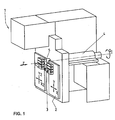
- FIG. 1 represents an example of a machine tool 1 of this type.
- these machines comprise a doll 4 and a barrel 5.
- a motor (not shown) drives the doll and the cannon in rotation (in the figure, the axis of rotation corresponds to the axis "z").
- the part or blank to be machined is fixed in the axis of rotation by clamps.
- the material to be machined may be in the form of a long bar held in the axis "z" of the cannon by bar clamping means.
- the machine tool 1 works one end of the bar and the doll 4 comprises bar feed means, which are provided to control the position of the bar along the axis "z".
- the machine tool 1 also comprises a "yx axis system” 2 designed to receive at least one machining tool 3. This tool may be, for example, a knife or a cutting tool.
- the axis system 2 is provided to be movable in a plane “xy” perpendicular to the axis of rotation "z". The displacement in the plane "xy” makes it possible to bring the tool 3 into the working position in contact with the workpiece and possibly to switch from one tool to another when the axis system "yx" 2 in several door.
- the "yx" 2 axis system is usually not designed to turn on itself. Consequently, the movements of the axis system 2, and therefore of the tool 3, are only translational movements (the tool always remains oriented in the same direction).
- the machine tool 1 must naturally also allow movement along the axis "z" of the tool relative to the workpiece. This displacement can, possibly, be obtained by moving the axis system 2 itself. However, most often, it is the workpiece that is moved along its axis "z” by the doll using its bar feed means. These movements along three axes "x, y, z" are controlled either manually or automatically.
- the movements of the "yx" axis system 2 can be controlled by numerically programmable electronic control means.
- the present invention relates to the latter type of machine tools, called numerical control, in which the movements along the three axes "x, y, z" are controlled by programmable electronic control means.
- a machine tool designed to work on a rotating part can generally only machine parts with concentric and coaxial cylindrical or conical spans, that is to say that the main axes of the various The staves are all aligned on a main longitudinal axis.
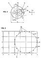
- a workpiece 11 provided with one or more bearing surfaces (referenced 12 and 13 in FIG. 2) eccentric to each other, it is normally necessary to stop the machine between the machining of the various bearing surfaces, to offset the workpiece in the spindle of the workpiece spindle and resume machining for the next eccentric scope.
- This requires many manipulations difficult to achieve by automatic means. Thus, such manipulations have a negative effect on machining precision as well as on the rate of work.
- said method is furthermore provided for operating a specially constructed machining machine and not a numerically controlled machining machine of known type whose tools only move in translation.
- the device described in this second document comprises means for moving the tool that allow movements of this tool in a plane (xy) perpendicular to the axis of rotation of the piece, but these means do not allow translational movements in each of the orthogonal directions.
- the displacements in the plane perpendicular to the axis of rotation of the part are displacements according to arcs of circles.
- the device of this third document comprises means for keeping a part in constant rotation about an axis, a tool mounted on a system of axes allowing displacements in perpendicular directions (X, Y) in a perpendicular plane (xy) to the axis of rotation, programmable control means for controlling the axis system according to the angular position of the part on its axis of rotation.
- the machining is performed by means of a rotary tool and it is the support of this rotary tool which is moved on a circular path (around the axis of the scope that it realizes) in synchronism with the rotation of the part.
- the device of US-A-5,396,821 is a special construction and does not consist of a numerically controlled machining machine of known type whose tools only move in translation.
- this third device is essentially the rotation of the tool that causes the removal of chips and the risk of formation of facets is certainly less than in the case of the invention, because in the case of the pending application it is the movement of rotation of the part that causes the removal of chips.
- the present invention aims to overcome the disadvantages of the prior art, in particular by providing a method for machining a workpiece comprising at least one non-concentric surface without the need to shift the workpiece spindle by a determined value. before starting the machining of the non-concentric scope.
- the part 11 of Figure 2 comprises a first cylindrical surface 12 having a certain diameter (D).
- first bearing surface 12 On this first bearing surface 12, there is a second cylindrical bearing surface 13 whose diameter (d) is smaller than that of the first bearing surface and whose longitudinal axis is offset by a value ⁇ relative to the longitudinal axis of the bearing surface. 12.
- the bar or blank to become the part is kept rotating.
- the axis of rotation "z" of the machine tool does not necessarily correspond to the geometric axis of one of the cylindrical bearing surfaces to be machined.
- the part to be produced could also include one or more additional cylindrical bearing surfaces, all eccentric relative to each other.
- the rotation frequency of the tool will be the same as the rotation frequency of the part on itself.
- the programming mode for controlling the execution of the above trajectory will naturally depend on the particular model of machine tool used. Those skilled in the art will be able to choose a programming mode adapted to the specifications of the CNC machine tool at their disposal. It is however useful to specify that it is important that the trajectory of the tool is well synchronized with the angular displacement of the rotating part on itself. If one wants to be able to work at reasonably high speeds, this last constraint requires the use of a numerical control that is both fast and precise.
- EP0 474 603 and EP0 543 034 which generally relate to machine tools, both describe a control method for moving a tool relative to a rotated workpiece. Both methods are characterized by the fact that the movements of the tool relative to the workpiece along the three axes "x, y, z" are calculated by an external programming unit, even before machining the workpiece. This feature has the advantage of allowing a high speed of execution even with a hardware whose computing power is average.
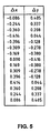
- step tables The movements of the tool relative to the workpiece are previously programmed in the form of "step tables" ( Figure 5). To do this, the travel time is first cut into small successive time intervals of fixed duration. Since the movement of the tool must be synchronized with the rotation of the workpiece, the duration of the time intervals must be chosen so that a complete spindle revolution can be completed in an integer of these intervals. time. On the other hand, he It is also necessary that the number of intervals subdividing a turn is sufficient to define an adequate number of points on the trajectory of the tool.
- FIG. 5 is a table whose two columns ⁇ x and ⁇ y respectively constitute "step tables" for the movements of the tool along the directions "x" and "y". These two tables each have 15 steps together defining the speed and direction of the tool along its circular path.
- Figure 5 gives step lengths in quite arbitrary units.
- the precision (the number of significant digits) is also arbitrary. Note that In practice, some numerically controlled machine tools make it possible to position the tool with a precision that can reach one-tenth of a micron.
- FIG. 3 gives the trajectory 16 corresponding to the pitch tables of FIG. 5.
- Each of the two axes of displacement of the tool is controlled separately by one of the pitch tables. Consequently, the resulting displacement of the tool 15 in the "xy" plane is theoretically performed by successive jumps along rectilinear segments 20, and the sequence of these rectilinear segments should produce a polygonal trajectory 16. If it were not corrected, this characteristic could constitute a crippling disadvantage.
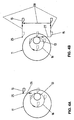
- FIG. 4 shows the example of a trajectory completed to include a stopping point (referenced 25) situated at a distance from the part.
- a stopping point referenced 25
- FIG. 4A in addition to the circular movement 16, there is shown a rectilinear linear input segment 26 corresponding to a movement of the knife 15 along the "y" axis from the stopping point to come into contact with the rotating part.
- Figure 4B shows a rectilinear segment 27 of "linear output” which also corresponds to a movement of the knife along the axis "y".
- the return to the stopping point is done by the path referenced 28.
- the passage through the stopping point 25 can be programmed at the end of each circular trajectory 16 of the tool 15, or less frequently according to the characteristics of the control system of the machine tool used.
- the “linear input” segment can, for example, be programmed in the form of a single step ⁇ y placed at the beginning of the sequence given in FIG. 5.
- the segment of "linear input” can be programmed as a single step ⁇ y placed at the beginning of the sequence given in FIG.
- linear output can also be programmed as a single ⁇ y step at the end of the same sequence.
- the return to the stopping point shown in FIG. 4B by the path referenced 28
- Providing a stopping point out of material may have other advantages in addition to that of preventing the risk, already mentioned, of desynchronization between the movement of the axis system "yx" and that of the rotating part. Indeed, the control software of a CNC machine tool is often provided to allow only a number of whole steps per spindle revolution. This precaution is known in the prior art to avoid problems when using the machine tool for combing operations. Due to rounding errors, this characteristic of the software sometimes leads to the control of a part revolution without movements of the "yx" axis system. However, if such immobilization of the "yx" axis system occurs during the execution of the method of the present invention, as already mentioned, it is desirable that the stopping point be located out of material.
- the operation is carried out either by removing chips in the direction of the "z" axis, either by removing chips in the direction of the "x" axis, or by a combination of these two directions. It will be understood that these different possibilities also exist when it comes to machining operations according to the method of the present invention.
- step tables to produce this trajectory in open loops based on the tables of Figure 5.
- the step table ⁇ y does not have to take it into account and, as in the previous example, it will consist essentially of several repetitions of the sequence of fifteen steps given in FIG. 5.
- the sequences of steps ⁇ x are obtained by adding at each step ⁇ x of FIG. 5, a constant quantity corresponding to the reduction of the radius X0 during the duration of a step.
- the part of which we have just described the machining comprises only cylindrical bearing surfaces whose axes are parallel.
- the method of the present invention also makes it possible, for example, to produce parts with eccentric conical bearing surfaces.
- to machine a conical bearing it suffices to operate as for a cylindrical bearing while taking into account the variation of the diameter "d" as the advance along the axis "z".
- the trajectory that the tool must traverse in the plane (xy) is not, either, a closed circular trajectory, but a trajectory consisting of a succession substantially circular open loops and constant radius.
- the "step tables" ⁇ x and ⁇ y to produce this trajectory in open loops can be obtained in a manner similar to that described for the previous example.
- the method of the present invention also makes it possible to produce spans whose axes are not parallel. Indeed, to machine such oblique bearing surfaces, it is sufficient to operate as for a parallel cylindrical bearing while taking into account the variation of the center distance " ⁇ " as the advance along the axis "z"". In the latter case, the trajectory that the tool must traverse in the plane (xy) is not, either, a circle but a spiral whose pitch depends on the variation of the center distance " ⁇ " as and when measuring the advance along the "z” axis.
- each step ⁇ x and ⁇ y is proportional to the center distance " ⁇ ".
- the method of the present invention is not limited to spans whose shape corresponds to one of the examples given above.
- Those skilled in the art will know how to determine the hourly equation of the tool in order to obtain other shapes of non-concentric bearing parts.
- the present invention does not limit this to spans of circular section. Indeed, by slightly changing the hourly equation of the tool to obtain, for example, an elliptical trajectory, it is possible to machine in particular eccentric ranges whose section is elliptical.
Landscapes
- Engineering & Computer Science (AREA)
- Human Computer Interaction (AREA)
- Manufacturing & Machinery (AREA)
- Physics & Mathematics (AREA)
- General Physics & Mathematics (AREA)
- Automation & Control Theory (AREA)
- Numerical Control (AREA)
- Turning (AREA)
Claims (12)
- Verfahren zur Bearbeitung von nicht konzentrischen Teilen mit Hilfe einer Werkzeugsmachine (1), wobei die Werkzeugsmaschine- dazu bestimmt ist, an einem Teil (11) zu arbeiten, der durch ein Ende einer um einen feste Drehachse (z) drehend gehaltenen Stange gebildet ist und- zudem ein Achsensystem (2) umfasst, das die Bewegungen eines Werkzeugs (3) erlaubt, wobei das besagte Wergzeug durch Translationsbewegungen in einer zu der besagten Drehachse(z) senkrecht liegenden Ebene (xy) verfahrbar ist und die Bewegungen in der Ebene (xy) durch programmierbare Steuermittel gesteuert sind;- wobei jedes nicht konzentrische Teil aus mindestens einem der Teile besteht, die durch ein Teil gebildet sind,- das mindestens eine erste und eine zweite zylindrische Ausladung (12, 13) umfasst, wobei die Längsachse der zweiten Ausladung um einen ö Abstand zu der Längsachse der ersten Ausladung versetzt angeordnet ist,- das mindestens eine konische oder kegelstumpfförmige nicht-konzentrische Ausladung umfasst, wobei das Radius X0 der Ausladung von der Stellung nach der Achse "z" abhängt und die Längsachse der zweiten Ausladung um einen δ Abstand zu der Längsachse der ersten Ausladung versetzt angeordnet ist,- das eine Ausladung umfasst, deren Längsachse schräg zu der besagten Drehachse (z) ausgerichtet ist, wobei der Abstand ö zwischen der Längsachse der gesagten Ausladung und der Drehachse (z) von der Stellung nach Achse "z" abhängt,wobei das Verfahren folgende Schritte umfasst:- Ermittlung der zeitlichen Gleichung einer vom Werkzeug (3) zurückzulegenden Bahn (16) in der zu der Drehachse (z) senkrecht liegenden besagten Ebene (xy), wobei die Bahn (16) wesentlich Schleifen bildet;- Programmierung der besagten Steuerungsmittel, damit das Werkzeug (3) die besagte Bahn (16) mit geeigneter Geschwindigkeit zurücklegen kann, wobei die Bahn mindestens eine Schleife umfasst, die vollständig in einer einer Drehung des besagten Teils (11) gleichen Zeitspanne befahren werden muss;- Durchführung der somit in den Steuermitteln programmierten Arbeit durch die Werkzeugsmaschine (1),wobei dieses Verfahren dadurch gekennzeichnet ist, dass die vom Werkzeug (3) zurückzulegende Bahn in der Ebene (xy) in Form zweier Bewegungsbefehlsreihenfolgen (Schritttabelle) programmiert ist, wobei eine dieser Bewegungsbefehlsreihenfolgen (Δx) die Bewegungen nach der Achse "x" und die weiteren Befehlsreihenfolgen (Δy) nach der Achse "y" betrifft,
wobei beide Befehlsreihenfolgen zu deren Parallelldurchführung vorgesehen sind, und die gleichzeitige Kombinierung eines Befehls aus jeder Reihenfolge einen geradelinigen Schritt in der Ebene (xy) bildet, wobei der Ausführungsrhythmus beider Bewegungsbefehlsreihenfolgen durch die programmierte Auswahl der Dauer (TE) einer Zeitspanne bestimmt ist. - Verfahren zur Bearbeitung von nicht konzentrischen Teilen nach vorhergehendem Anspruch, dadurch gekennzeichnet dass bei einem Teil, das mindestens eine erste und eine zweite zylindrische Ausladung (12, 13) umfaßt, wobei die Längsachse der zweiten Ausladung um einen δ Abstand zu der Längsachse der ersten Ausladung versetzt angeordnet ist,
die zeitliche Gleichung für eine Schrittbewegung des Werkzeuges ist :

wo t:= der abgelaufenen Zeit und
XO: = dem Radius der zweiten Ausladung. - Verfahren zur Bearbeitung von nicht konzentrischen Teilen nach vorhergehendem Anspruch, dadurch gekennzeichnet dass, die Befehle (Δx), die die Bewegungsbefehlsreihenfolge nach der Achse "x" bilden, durch das Verhältnis gegeben sind:


- Verfahren zur Bearbeitung von nicht konzentrischen Teilen nach vorhergehendem Anspruch, dadurch gekennzeichnet, dass der programmierte Wert eines XO Radius der Ausladung in dem Maße kleiner wird, wie die Verarbeitung vorangeht.
- Verfahren zur Bearbeitung von nicht konzentrischen Teilen nach Anspruch 1, dadurch gekennzeichnet, dass bei einem Teil mit einer konischen oder kegelstumpfförmigen nicht-konzentrischen Ausladung, wobei der XO Radius dieser Ausladung von der Stellung der Achse "z" abhängt und wobei die Längsachse der Ausladung um einen δ Abstand zu der Längsachse der ersten Ausladung versetzt angeordnet ist,
die zeitliche Gleichung für eine Schrittbewegung des Werkzeuges ist :

mit j = Vollanteil von t/TE
wo t:= der abgelaufenen Zeit und
XO: = dem Radius der zweiten Ausladung. - Verfahren zur Bearbeitung von nicht konzentrischen Teilen nach Anspruch 1, dadurch gekennzeichnet, dass bei einem Teil, die eine Ausladung umfasst, deren Längsachse schräg zu der besagten Drehachse (z) ausgerichtet ist, wobei der Abstand δ zwischen der Längsachse der besagten Ausladung und der Drehachse (z) von der Stellung nach Achse "z" abhängt, die zeitliche Gleichung für eine Schrittbewegung des Werkzeuges ist :

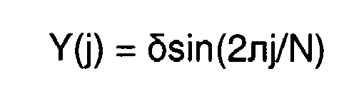
mit j = Vollanteil von t/TE
wo t:= der abgelaufenen Zeit und
XO: = dem Radius der zweiten Ausladung. - Verfahren zur Bearbeitung von nicht konzentrischen Teilen nach Anspruch 1, dadurch gekennzeichnet dass die vom Werkzeug zurückzulegende besagte Bahn einen Anhaltspunkt außer Materie (25) umfasst.
- Verfahren zur Bearbeitung von nicht konzentrischen Teilen nach vorhergehendem Anspruch, dadurch gekennzeichnet dass die Bewegungsbefehlsreihenfolgen mindestens einen linearen Eingangspunkt (26), einen linearen Ausgangsschritt (27) und Wendepunkte (28) zum Anhaltspunkt (25) umfassen.
- Verfahren zur Bearbeitung von nicht konzentrischen Teilen nach vorhergehendem Anspruch, dadurch gekennzeichnet, dass die Schritte ineinander folgen, um eine konstante Geschwindigkeit als Absoluter Wert zu erzeugen.
- Verfahren zur Bearbeitung von nicht konzentrischen Teilen nach vorhergehendem Anspruch, dadurch gekennzeichnet, dass die besagte Bahn programmierte Schleifen umfasst, um höchstens in fünfzehn Zeitabständen (TE) durchgefahren zu werden.
- Verfahren zur Bearbeitung von nicht konzentrischen Teilen nach vorhergehendem Anspruch, dadurch gekennzeichnet, dass die besagte Bahn programmierte Schleifen umfasst, um höchstens in acht Zeitabständen (TE) durchgefahren zu werden.
- Werkzeugsmaschine dadurch gekennzeichnet, dass sie zu der Durchführung des Verfahrens nach einem der vorhergehenden Ansprüche programmiert ist.
Priority Applications (1)
| Application Number | Priority Date | Filing Date | Title |
|---|---|---|---|
| EP19990810379 EP1028362B1 (de) | 1999-02-11 | 1999-05-04 | Werkzeugsteuerung zur nicht-konzentrischen Bearbeitung |
Applications Claiming Priority (3)
| Application Number | Priority Date | Filing Date | Title |
|---|---|---|---|
| EP99810114 | 1999-02-11 | ||
| EP99810114 | 1999-02-11 | ||
| EP19990810379 EP1028362B1 (de) | 1999-02-11 | 1999-05-04 | Werkzeugsteuerung zur nicht-konzentrischen Bearbeitung |
Publications (3)
| Publication Number | Publication Date |
|---|---|
| EP1028362A2 EP1028362A2 (de) | 2000-08-16 |
| EP1028362A3 EP1028362A3 (de) | 2002-10-30 |
| EP1028362B1 true EP1028362B1 (de) | 2006-10-18 |
Family
ID=26153746
Family Applications (1)
| Application Number | Title | Priority Date | Filing Date |
|---|---|---|---|
| EP19990810379 Expired - Lifetime EP1028362B1 (de) | 1999-02-11 | 1999-05-04 | Werkzeugsteuerung zur nicht-konzentrischen Bearbeitung |
Country Status (1)
| Country | Link |
|---|---|
| EP (1) | EP1028362B1 (de) |
Cited By (1)
| Publication number | Priority date | Publication date | Assignee | Title |
|---|---|---|---|---|
| EP4163744A1 (de) * | 2021-10-08 | 2023-04-12 | Star Micronics Co., Ltd. | Werkzeugmaschine und verfahren zur bestimmung des werkzeugbewegungsweges |
Families Citing this family (1)
| Publication number | Priority date | Publication date | Assignee | Title |
|---|---|---|---|---|
| JP2005288563A (ja) * | 2004-03-31 | 2005-10-20 | Yamazaki Mazak Corp | 加工プログラム作成方法、及び加工プログラム作成装置 |
Family Cites Families (7)
| Publication number | Priority date | Publication date | Assignee | Title |
|---|---|---|---|---|
| WO1985000545A1 (fr) * | 1983-08-01 | 1985-02-14 | Berghaus, Horst | Procede de fabrication de pieces a usiner avec profil interieur et/ou exterieur polygonal et installations pour realiser ce procede |
| JP2736359B2 (ja) * | 1992-01-10 | 1998-04-02 | オークマ株式会社 | カム切削旋盤の刃物台 |
| JP2996804B2 (ja) * | 1992-04-30 | 2000-01-11 | オークマ株式会社 | 偏心形状加工装置 |
| JPH068105A (ja) * | 1992-06-29 | 1994-01-18 | Komatsu Ltd | 円筒形状加工装置 |
| US5467675A (en) * | 1993-11-15 | 1995-11-21 | North Carolina State University | Apparatus and method for forming a workpiece surface into a non-rotationally symmetric shape |
| TW301619B (de) * | 1994-10-07 | 1997-04-01 | Toshiba Machine Co Ltd | |
| DE69529907T2 (de) * | 1995-11-17 | 2003-12-18 | Tornos S.A., Moutier | Verfahren und Programm einer numerischen Steuerung einer Werkzeugmaschine und numerische Steuerung, die mit Mitteln dieses Programms arbeitet |
-
1999
- 1999-05-04 EP EP19990810379 patent/EP1028362B1/de not_active Expired - Lifetime
Cited By (2)
| Publication number | Priority date | Publication date | Assignee | Title |
|---|---|---|---|---|
| EP4163744A1 (de) * | 2021-10-08 | 2023-04-12 | Star Micronics Co., Ltd. | Werkzeugmaschine und verfahren zur bestimmung des werkzeugbewegungsweges |
| US12496673B2 (en) | 2021-10-08 | 2025-12-16 | Star Micronics Co., Ltd. | Machine tool and method of deciding tool moving path |
Also Published As
| Publication number | Publication date |
|---|---|
| EP1028362A3 (de) | 2002-10-30 |
| EP1028362A2 (de) | 2000-08-16 |
Similar Documents
| Publication | Publication Date | Title |
|---|---|---|
| FR2651705A1 (fr) | Procede pour la finition des flancs de dents de roues dentees, notamment trempees, et outil pour la mise en óoeuvre de ce procede. | |
| EP1930111A1 (de) | Wirbelkopf und seine Anwendung | |
| FR2485415A1 (fr) | Tour a fileter a vibration pour decolletage de precision | |
| EP1028362B1 (de) | Werkzeugsteuerung zur nicht-konzentrischen Bearbeitung | |
| EP0340158B1 (de) | Drehautomat zum Bearbeiten von Draht | |
| EP4132739A1 (de) | Laserdrehsystem, laserdrehverfahren mit solch einem system und durch solch ein verfahren erhaltenes teil | |
| EP0050179B1 (de) | Numerisch gesteuerter Drehautomat | |
| FR2582559A1 (fr) | Procede pour mesurer et/ou regler la position d'un element de reference mobile d'une machine-outil et dispositif pour la mise en oeuvre du procede | |
| EP0015300A1 (de) | Verfahren zum Drehen und Drehbank für die Anwendung dieses Verfahrens | |
| EP0474603A1 (de) | Verfahren und Gerät zum Steuern einer oder mehrerer Achsen einer Werkzeugmaschine | |
| FR2556259A1 (fr) | Procede et dispositif pour la fabrication et l'usinage de roues dentees | |
| EP4101569B1 (de) | Gewindeschneideverfahren | |
| CH702859A2 (fr) | Système et procédé de décolletage-fraisage. | |
| CH718688A2 (fr) | Machine d'usinage d'une pièce micromécanique et procédé d'usinage mis en oeuvre par ladite machine. | |
| FR2639564A1 (fr) | Mandrin a centrage automatique | |
| EP0693340A1 (de) | Verfahren zum Herstellen von Ringen durch Zerschneiden eines metallischen Rohres und Vorrichtung zu seiner Durchführung | |
| FR2608480A1 (fr) | Procede pour l'usinage fin de surfaces externes presentant une symetrie de revolution sur des pieces d'oeuvre | |
| FR2567434A1 (fr) | Dispositif pour la fabrication ou l'usinage de roues dentees par roulement sur un outil comportant des surfaces de travail abrasives | |
| EP0899045B1 (de) | Mehrspindeldrehmaschine mit NC-Steuerung und entsprechendes Bearbeitungsverfahren | |
| FR2716638A1 (fr) | Procédé de fraisage d'au moins une région localisée d'une pièce. | |
| EP1762319A1 (de) | Verfahren zur Optimierung der Funktion einer Werkzeugmachine mit einer zusätzlichen Stangenführungseinrichtung und entsprechende Werkzeugmaschine | |
| EP1285716A1 (de) | Abwälzbearbeitung | |
| WO2025057557A1 (ja) | 切屑分断旋削制御装置及びそれを備えた工作機械 | |
| FR2702979A1 (fr) | Machine-outil d'usinage à commande automatique pour la fabrication par usinage selon trois axes de pièces mécaniques, à partir d'une barre à plusieurs faces. | |
| FR2736571A1 (fr) | Amelioration concernant les machines-outils a commande numerique |
Legal Events
| Date | Code | Title | Description |
|---|---|---|---|
| PUAI | Public reference made under article 153(3) epc to a published international application that has entered the european phase |
Free format text: ORIGINAL CODE: 0009012 |
|
| AK | Designated contracting states |
Kind code of ref document: A2 Designated state(s): AT BE CH CY DE DK ES FI FR GB GR IE IT LI LU MC NL PT SE |
|
| AX | Request for extension of the european patent |
Free format text: AL;LT;LV;MK;RO;SI |
|
| PUAL | Search report despatched |
Free format text: ORIGINAL CODE: 0009013 |
|
| AK | Designated contracting states |
Kind code of ref document: A3 Designated state(s): AT BE CH CY DE DK ES FI FR GB GR IE IT LI LU MC NL PT SE |
|
| AX | Request for extension of the european patent |
Free format text: AL;LT;LV;MK;RO;SI |
|
| RAP1 | Party data changed (applicant data changed or rights of an application transferred) |
Owner name: TORNOS SA |
|
| 17P | Request for examination filed |
Effective date: 20030404 |
|
| AKX | Designation fees paid |
Designated state(s): AT BE CH CY DE DK ES LI |
|
| RBV | Designated contracting states (corrected) |
Designated state(s): CH DE ES FR GB IT LI SE |
|
| 17Q | First examination report despatched |
Effective date: 20031009 |
|
| GRAP | Despatch of communication of intention to grant a patent |
Free format text: ORIGINAL CODE: EPIDOSNIGR1 |
|
| GRAC | Information related to communication of intention to grant a patent modified |
Free format text: ORIGINAL CODE: EPIDOSCIGR1 |
|
| GRAS | Grant fee paid |
Free format text: ORIGINAL CODE: EPIDOSNIGR3 |
|
| GRAA | (expected) grant |
Free format text: ORIGINAL CODE: 0009210 |
|
| AK | Designated contracting states |
Kind code of ref document: B1 Designated state(s): AT BE CH CY DE DK ES FI FR GB GR IE IT LI LU MC NL PT SE |
|
| PG25 | Lapsed in a contracting state [announced via postgrant information from national office to epo] |
Ref country code: NL Free format text: LAPSE BECAUSE OF FAILURE TO SUBMIT A TRANSLATION OF THE DESCRIPTION OR TO PAY THE FEE WITHIN THE PRESCRIBED TIME-LIMIT Effective date: 20061018 Ref country code: IE Free format text: LAPSE BECAUSE OF FAILURE TO SUBMIT A TRANSLATION OF THE DESCRIPTION OR TO PAY THE FEE WITHIN THE PRESCRIBED TIME-LIMIT Effective date: 20061018 Ref country code: AT Free format text: LAPSE BECAUSE OF FAILURE TO SUBMIT A TRANSLATION OF THE DESCRIPTION OR TO PAY THE FEE WITHIN THE PRESCRIBED TIME-LIMIT Effective date: 20061018 |
|
| RBV | Designated contracting states (corrected) |
Designated state(s): AT BE CH CY DE DK ES FI FR GB GR IE IT LI LU MC NL PT SE |
|
| REG | Reference to a national code |
Ref country code: GB Ref legal event code: FG4D Free format text: NOT ENGLISH |
|
| REG | Reference to a national code |
Ref country code: IE Ref legal event code: FG4D Free format text: LANGUAGE OF EP DOCUMENT: FRENCH Ref country code: CH Ref legal event code: EP |
|
| REF | Corresponds to: |
Ref document number: 69933644 Country of ref document: DE Date of ref document: 20061130 Kind code of ref document: P |
|
| REG | Reference to a national code |
Ref country code: CH Ref legal event code: NV Representative=s name: BOVARD AG PATENTANWAELTE |
|
| PG25 | Lapsed in a contracting state [announced via postgrant information from national office to epo] |
Ref country code: DK Free format text: LAPSE BECAUSE OF FAILURE TO SUBMIT A TRANSLATION OF THE DESCRIPTION OR TO PAY THE FEE WITHIN THE PRESCRIBED TIME-LIMIT Effective date: 20070118 |
|
| PG25 | Lapsed in a contracting state [announced via postgrant information from national office to epo] |
Ref country code: ES Free format text: LAPSE BECAUSE OF FAILURE TO SUBMIT A TRANSLATION OF THE DESCRIPTION OR TO PAY THE FEE WITHIN THE PRESCRIBED TIME-LIMIT Effective date: 20070129 |
|
| REG | Reference to a national code |
Ref country code: SE Ref legal event code: TRGR |
|
| GBT | Gb: translation of ep patent filed (gb section 77(6)(a)/1977) |
Effective date: 20070122 |
|
| PG25 | Lapsed in a contracting state [announced via postgrant information from national office to epo] |
Ref country code: PT Free format text: LAPSE BECAUSE OF FAILURE TO SUBMIT A TRANSLATION OF THE DESCRIPTION OR TO PAY THE FEE WITHIN THE PRESCRIBED TIME-LIMIT Effective date: 20070319 |
|
| NLV1 | Nl: lapsed or annulled due to failure to fulfill the requirements of art. 29p and 29m of the patents act | ||
| PGFP | Annual fee paid to national office [announced via postgrant information from national office to epo] |
Ref country code: SE Payment date: 20070417 Year of fee payment: 9 |
|
| REG | Reference to a national code |
Ref country code: IE Ref legal event code: FD4D |
|
| PLBE | No opposition filed within time limit |
Free format text: ORIGINAL CODE: 0009261 |
|
| STAA | Information on the status of an ep patent application or granted ep patent |
Free format text: STATUS: NO OPPOSITION FILED WITHIN TIME LIMIT |
|
| 26N | No opposition filed |
Effective date: 20070719 |
|
| BERE | Be: lapsed |
Owner name: TORNOS SA Effective date: 20070531 |
|
| PG25 | Lapsed in a contracting state [announced via postgrant information from national office to epo] |
Ref country code: MC Free format text: LAPSE BECAUSE OF NON-PAYMENT OF DUE FEES Effective date: 20070531 |
|
| PG25 | Lapsed in a contracting state [announced via postgrant information from national office to epo] |
Ref country code: BE Free format text: LAPSE BECAUSE OF NON-PAYMENT OF DUE FEES Effective date: 20070531 |
|
| PG25 | Lapsed in a contracting state [announced via postgrant information from national office to epo] |
Ref country code: GR Free format text: LAPSE BECAUSE OF FAILURE TO SUBMIT A TRANSLATION OF THE DESCRIPTION OR TO PAY THE FEE WITHIN THE PRESCRIBED TIME-LIMIT Effective date: 20070119 |
|
| PG25 | Lapsed in a contracting state [announced via postgrant information from national office to epo] |
Ref country code: LU Free format text: LAPSE BECAUSE OF NON-PAYMENT OF DUE FEES Effective date: 20070504 Ref country code: FI Free format text: LAPSE BECAUSE OF FAILURE TO SUBMIT A TRANSLATION OF THE DESCRIPTION OR TO PAY THE FEE WITHIN THE PRESCRIBED TIME-LIMIT Effective date: 20061018 Ref country code: CY Free format text: LAPSE BECAUSE OF FAILURE TO SUBMIT A TRANSLATION OF THE DESCRIPTION OR TO PAY THE FEE WITHIN THE PRESCRIBED TIME-LIMIT Effective date: 20061018 |
|
| PG25 | Lapsed in a contracting state [announced via postgrant information from national office to epo] |
Ref country code: SE Free format text: LAPSE BECAUSE OF NON-PAYMENT OF DUE FEES Effective date: 20080505 |
|
| REG | Reference to a national code |
Ref country code: CH Ref legal event code: PFA Owner name: TORNOS SA Free format text: TORNOS SA#RUE INDUSTRIELLE 111#2740 MOUTIER (CH) -TRANSFER TO- TORNOS SA#RUE INDUSTRIELLE 111#2740 MOUTIER (CH) |
|
| PGFP | Annual fee paid to national office [announced via postgrant information from national office to epo] |
Ref country code: GB Payment date: 20110520 Year of fee payment: 13 |
|
| PGFP | Annual fee paid to national office [announced via postgrant information from national office to epo] |
Ref country code: FR Payment date: 20120601 Year of fee payment: 14 |
|
| GBPC | Gb: european patent ceased through non-payment of renewal fee |
Effective date: 20120504 |
|
| PG25 | Lapsed in a contracting state [announced via postgrant information from national office to epo] |
Ref country code: GB Free format text: LAPSE BECAUSE OF NON-PAYMENT OF DUE FEES Effective date: 20120504 |
|
| PGFP | Annual fee paid to national office [announced via postgrant information from national office to epo] |
Ref country code: CH Payment date: 20130508 Year of fee payment: 15 |
|
| PGFP | Annual fee paid to national office [announced via postgrant information from national office to epo] |
Ref country code: IT Payment date: 20130527 Year of fee payment: 15 |
|
| REG | Reference to a national code |
Ref country code: FR Ref legal event code: ST Effective date: 20140131 |
|
| PG25 | Lapsed in a contracting state [announced via postgrant information from national office to epo] |
Ref country code: FR Free format text: LAPSE BECAUSE OF NON-PAYMENT OF DUE FEES Effective date: 20130531 |
|
| REG | Reference to a national code |
Ref country code: CH Ref legal event code: PL |
|
| PG25 | Lapsed in a contracting state [announced via postgrant information from national office to epo] |
Ref country code: CH Free format text: LAPSE BECAUSE OF NON-PAYMENT OF DUE FEES Effective date: 20140531 Ref country code: LI Free format text: LAPSE BECAUSE OF NON-PAYMENT OF DUE FEES Effective date: 20140531 |
|
| PG25 | Lapsed in a contracting state [announced via postgrant information from national office to epo] |
Ref country code: IT Free format text: LAPSE BECAUSE OF NON-PAYMENT OF DUE FEES Effective date: 20140504 |
|
| PGFP | Annual fee paid to national office [announced via postgrant information from national office to epo] |
Ref country code: DE Payment date: 20160520 Year of fee payment: 18 |
|
| REG | Reference to a national code |
Ref country code: DE Ref legal event code: R119 Ref document number: 69933644 Country of ref document: DE |
|
| PG25 | Lapsed in a contracting state [announced via postgrant information from national office to epo] |
Ref country code: DE Free format text: LAPSE BECAUSE OF NON-PAYMENT OF DUE FEES Effective date: 20171201 |