EP1028362A2 - Werkzeugsteuerung zur nicht-konzentrischen Bearbeitung - Google Patents
Werkzeugsteuerung zur nicht-konzentrischen Bearbeitung Download PDFInfo
- Publication number
- EP1028362A2 EP1028362A2 EP99810379A EP99810379A EP1028362A2 EP 1028362 A2 EP1028362 A2 EP 1028362A2 EP 99810379 A EP99810379 A EP 99810379A EP 99810379 A EP99810379 A EP 99810379A EP 1028362 A2 EP1028362 A2 EP 1028362A2
- Authority
- EP
- European Patent Office
- Prior art keywords
- tool
- axis
- parts according
- concentric parts
- orders
- Prior art date
- Legal status (The legal status is an assumption and is not a legal conclusion. Google has not performed a legal analysis and makes no representation as to the accuracy of the status listed.)
- Granted
Links
Images


Classifications
-
- G—PHYSICS
- G05—CONTROLLING; REGULATING
- G05B—CONTROL OR REGULATING SYSTEMS IN GENERAL; FUNCTIONAL ELEMENTS OF SUCH SYSTEMS; MONITORING OR TESTING ARRANGEMENTS FOR SUCH SYSTEMS OR ELEMENTS
- G05B19/00—Program-control systems
- G05B19/02—Program-control systems electric
- G05B19/18—Numerical control [NC], i.e. automatically operating machines, in particular machine tools, e.g. in a manufacturing environment, so as to execute positioning, movement or co-ordinated operations by means of program data in numerical form
- G05B19/182—Numerical control [NC], i.e. automatically operating machines, in particular machine tools, e.g. in a manufacturing environment, so as to execute positioning, movement or co-ordinated operations by means of program data in numerical form characterised by the machine tool function, e.g. thread cutting, cam making, tool direction control
- G05B19/184—Generation of cam-like surfaces
-
- G—PHYSICS
- G05—CONTROLLING; REGULATING
- G05B—CONTROL OR REGULATING SYSTEMS IN GENERAL; FUNCTIONAL ELEMENTS OF SUCH SYSTEMS; MONITORING OR TESTING ARRANGEMENTS FOR SUCH SYSTEMS OR ELEMENTS
- G05B2219/00—Program-control systems
- G05B2219/30—Nc systems
- G05B2219/49—Nc machine tool, till multiple
- G05B2219/49313—Machining about eccentric center different from rotational center of workpiece
-
- G—PHYSICS
- G05—CONTROLLING; REGULATING
- G05B—CONTROL OR REGULATING SYSTEMS IN GENERAL; FUNCTIONAL ELEMENTS OF SUCH SYSTEMS; MONITORING OR TESTING ARRANGEMENTS FOR SUCH SYSTEMS OR ELEMENTS
- G05B2219/00—Program-control systems
- G05B2219/30—Nc systems
- G05B2219/50—Machine tool, machine tool null till machine tool work handling
- G05B2219/50216—Synchronize speed and position of several axis, spindles
Definitions
- the present invention generally relates to machine tools (especially lathes) which are designed to work on a maintained part in rotation, and which include programmable electronic means controlling a system of axes allowing the movement of a tool in the plane perpendicular to the axis of rotation of the part.
- the present invention relates more particularly to a process for machining parts comprising non-coaxial or non-concentric spans with a machine tool such as described above.
- the present invention also relates to machine tools which are programmed to implement the process of present invention.
- Figure 1 shows an example of a machine tool 1 of this type.
- machines include a headstock 4 and a barrel 5.
- a motor (not shown) drives the doll and the cannon in rotation (in the figure, the axis of rotation corresponds to the "z" axis).
- the workpiece or blank to be machined is fixed in the axis of rotation by pliers.
- the material to be machined can be in the form of a long bar held in the "z" axis cannon by bar clamping means.
- the machine tool 1 works one end of the bar and the headstock 4 has means bar feeders, which are intended to control the position of the bar along the "z" axis.
- the machine tool 1 also includes a "y-x axis system” 2 designed to receive at least one machining tool 3.
- This tool can be, for example example, a knife or a cutting-off tool.
- Axis system 2 is planned to be movable in an "xy” plane perpendicular to the axis of rotation "Z". The displacement in the “xy” plane makes it possible to bring the tool 3 into position working in contact with the workpiece and possibly moving from a tool to another when the axis system “y-x” 2 carries more than one.
- the “y-x” axis system »2 is usually not intended to turn on itself. In Consequently, the movements of the axis system 2, and therefore of the tool 3, are only translational movements (the tool always remains oriented in the same direction).
- the machine tool 1 must naturally also allow a displacement along the "z" axis of the tool relative to the workpiece. This displacement can possibly be obtained by displacement of the system of axes 2 itself. However, most often it is the workpiece that is moved along its "z” axis by the doll using its means bar feed. These displacements along three axes "x, y, z" are controlled either manually or automatically.
- the movements of the axis system "y-x" 2 can be controlled by means digitally programmable control electronics.
- the current invention relates to the latter type of machine tools, called command numerical, in which the displacements along the three axes "x, y, z" are subject to programmable electronic control means.
- a machine tool designed to work on a rotating part can generally only machine parts having concentric and coaxial cylindrical or conical spans, i.e. that the main axes of the various scopes are all aligned on an axis main longitudinal.
- a part 11 provided with one or several scopes (referenced 12 and 13 in Figure 2) offset between them, it it is normally necessary to stop the machine between the machining of the various bearings, to shift part in the clamp of the workpiece spindle and resume machining for the next offset span.
- This requires many manipulations difficult to perform by automatic means. Thus, such manipulations negatively affect the machining precision, as well as the pace of work.
- the present invention aims to remedy the drawbacks of the art prior art, in particular, by providing a method for machining a workpiece comprising at least one non-concentric bearing without the need to offset the workpiece spindle by a specified value before starting machining of the non-concentric bearing.
- the part 11 of FIG. 2 comprises a first cylindrical bearing 12 having a certain diameter (D).
- first litter 12 On this first litter 12, we have a second cylindrical seat 13 whose diameter (d) is less than that of the first litter and whose longitudinal axis is offset by a value ⁇ relative to the longitudinal axis of the span 12.
- the bar or the blank intended to become the part is kept rotating.
- the axis of rotation “z” of the machine tool does not necessarily correspond to the axis geometric of one of the cylindrical surfaces to be machined.
- the part to be produced could also have one or more cylindrical bearings additional, all offset from each other.
- the frequency of rotation of the tool will be the same as the frequency of rotation of the workpiece on itself.
- X (t) XO + ⁇ cos ( ⁇ t)
- the programming mode to control the execution of the trajectory above will naturally depend on the particular model of machine tool used. Those skilled in the art will be able to choose a programming mode adapted to the specifications of the numerically controlled machine tool which it has. It is however useful to clarify that it is important that the trajectory of the tool is well synchronized with the angular movement of the workpiece turning on itself. If you want to be able to work at speeds reasonably high, this last constraint requires the use of a digital control that is both fast and precise.
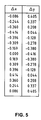
- step tables The movements of the tool relative to the workpiece are previously programmed in the form of "step tables" ( Figure 5).
- the travel time is first cut into small intervals successive times of fixed duration.
- the duration of the time intervals so as to allow the completion of a lap of full spindle into an integer of these time intervals.
- the number of intervals subdividing a lap must also be sufficient to define an adequate number of points on the tool path.
- Figure 5 attached is a table with the two columns ⁇ x and ⁇ y respectively constitute "step tables" for the displacements of the tool in the “x” and “y” directions. These two tables each have 15 pitch jointly defining the speed and the direction of the tool along its circular trajectory. As an example, Figure 5 shows the step lengths in completely arbitrary units. Similarly, the precision (the number of significant digits) is also arbitrary. Note that practical, some CNC machine tools allow position the tool with an accuracy that can reach a tenth of a micron.
- step tables include normally a greater number of steps.
- step tables ⁇ x and ⁇ y will contain several repetitions of the 15 step sequence given in Figure 5.
- Figure 3 gives the trajectory 16 corresponding to the step tables of figure 5.
- Each of the two axes of movement of the tool is controlled separately by one of the step tables.
- the displacement resulting from tool 15 in the “xy” plane is theoretically performed by jumps successive according to rectilinear segments 20, and the sequence of these rectilinear segments should produce a polygonal path 16. If she was not corrected, this characteristic could be a disadvantage unacceptable.
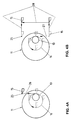
- FIG. 4 shows the example of a trajectory completed to include a breakpoint (referenced 25) located at a distance from the room.
- a rectilinear segment 26 "linear input” corresponding to a displacement of the knife 15 along the "y" axis from the stopping point to come into contact with the rotating part.
- FIG. 4B shows a rectilinear segment 27 of “linear output” which also corresponds to a movement of the knife along the "y" axis.
- the return to the stopping point is made by the path referenced 28.
- the passing through the breakpoint 25 can be programmed at the end of each circular path 16 of the tool 15, or less frequently depending on the characteristics of the control system of the machine tool used.
- the "linear input” segment can, for example, be programmed as a single step ⁇ y placed at the start of the sequence given in Figure 5.
- the segment of "output linear ” can also be programmed as a single ⁇ y step placed at the end of the same sequence.
- the return to the point stop (represented in FIG. 4B by the path referenced 28) can also be programmed as a sequence of steps.
- step tables to produce this trajectory in open loops based on the tables in figure 5.
- the step table ⁇ y has not take it into account and, as in the previous example, it will consisting essentially of several repetitions of the sequence of fifteen not given in FIG. 5.
- the step sequences ⁇ x are obtained by adding, at each step ⁇ x in FIG. 5, a constant quantity corresponding to the reduction of the X0 radius during the duration of a step.
- the part whose machining we have just described comprises only cylindrical bearings whose axes are parallel.
- the man of profession will understand that the process of the present invention also allows to produce, for example, parts with eccentric tapered seats. Indeed, to machine a conical bearing, it suffices to operate as for a cylindrical bearing while taking into account the variation in diameter "d" as and as it advances along the "z" axis. So, similar to what is explained in the previous paragraph, the trajectory that must travel the tool in the plane (xy) is not, either, a closed circular trajectory, but a trajectory made up of a succession of open loops substantially circular and of constant radius.
- the "step tables" ⁇ x and ⁇ y to produce this trajectory in open loops can be obtained from analogously to what was described for the previous example.
- the method of the present invention also makes it possible to produce spans whose axes are not parallel. Indeed, to machine such oblique spans, it suffices to operate as for a parallel cylindrical bearing while taking into account the variation of the center distance " ⁇ " as the advance along the axis "z " In the latter case, the trajectory that the tool must travel in the plane (xy) is not, either, a circle but a spiral whose pitch depends on the variation of the center distance " ⁇ " as and advance measurement along the "z” axis.
- each step ⁇ x and ⁇ y is proportional to the distance " ⁇ ". So we get the “Step tables” corresponding to the spiral path above, in multiplying the value of each step by a coefficient proportional to the value the center distance " ⁇ " at the time of the execution of this step.
- the method of the present invention is not limited to scopes whose shape corresponds to one of the examples given above.
- the skilled person will, in fact, determine the hourly equation of the tool to obtain other forms of part with non-concentric spans.
- the present invention is not limited to spans of circular section. Indeed, by slightly modifying the equation tool schedule to get for example an elliptical trajectory it's possible to machine in particular eccentric spans whose cross-section is elliptical.
Landscapes
- Engineering & Computer Science (AREA)
- Human Computer Interaction (AREA)
- Manufacturing & Machinery (AREA)
- Physics & Mathematics (AREA)
- General Physics & Mathematics (AREA)
- Automation & Control Theory (AREA)
- Numerical Control (AREA)
- Turning (AREA)
Priority Applications (1)
| Application Number | Priority Date | Filing Date | Title |
|---|---|---|---|
| EP19990810379 EP1028362B1 (de) | 1999-02-11 | 1999-05-04 | Werkzeugsteuerung zur nicht-konzentrischen Bearbeitung |
Applications Claiming Priority (3)
| Application Number | Priority Date | Filing Date | Title |
|---|---|---|---|
| EP99810114 | 1999-02-11 | ||
| EP99810114 | 1999-02-11 | ||
| EP19990810379 EP1028362B1 (de) | 1999-02-11 | 1999-05-04 | Werkzeugsteuerung zur nicht-konzentrischen Bearbeitung |
Publications (3)
| Publication Number | Publication Date |
|---|---|
| EP1028362A2 true EP1028362A2 (de) | 2000-08-16 |
| EP1028362A3 EP1028362A3 (de) | 2002-10-30 |
| EP1028362B1 EP1028362B1 (de) | 2006-10-18 |
Family
ID=26153746
Family Applications (1)
| Application Number | Title | Priority Date | Filing Date |
|---|---|---|---|
| EP19990810379 Expired - Lifetime EP1028362B1 (de) | 1999-02-11 | 1999-05-04 | Werkzeugsteuerung zur nicht-konzentrischen Bearbeitung |
Country Status (1)
| Country | Link |
|---|---|
| EP (1) | EP1028362B1 (de) |
Cited By (2)
| Publication number | Priority date | Publication date | Assignee | Title |
|---|---|---|---|---|
| EP1582951A3 (de) * | 2004-03-31 | 2009-03-04 | Yamazaki Mazak Corporation | Verfahren und Vorrichtung zur Herstellung von Bearbeitungsprogrammen |
| JP2023056848A (ja) * | 2021-10-08 | 2023-04-20 | スター精密株式会社 | 工作機械、及び、工具移動経路決定方法 |
Family Cites Families (7)
| Publication number | Priority date | Publication date | Assignee | Title |
|---|---|---|---|---|
| WO1985000545A1 (fr) * | 1983-08-01 | 1985-02-14 | Berghaus, Horst | Procede de fabrication de pieces a usiner avec profil interieur et/ou exterieur polygonal et installations pour realiser ce procede |
| JP2736359B2 (ja) * | 1992-01-10 | 1998-04-02 | オークマ株式会社 | カム切削旋盤の刃物台 |
| JP2996804B2 (ja) * | 1992-04-30 | 2000-01-11 | オークマ株式会社 | 偏心形状加工装置 |
| JPH068105A (ja) * | 1992-06-29 | 1994-01-18 | Komatsu Ltd | 円筒形状加工装置 |
| US5467675A (en) * | 1993-11-15 | 1995-11-21 | North Carolina State University | Apparatus and method for forming a workpiece surface into a non-rotationally symmetric shape |
| TW301619B (de) * | 1994-10-07 | 1997-04-01 | Toshiba Machine Co Ltd | |
| DE69529907T2 (de) * | 1995-11-17 | 2003-12-18 | Tornos S.A., Moutier | Verfahren und Programm einer numerischen Steuerung einer Werkzeugmaschine und numerische Steuerung, die mit Mitteln dieses Programms arbeitet |
-
1999
- 1999-05-04 EP EP19990810379 patent/EP1028362B1/de not_active Expired - Lifetime
Cited By (2)
| Publication number | Priority date | Publication date | Assignee | Title |
|---|---|---|---|---|
| EP1582951A3 (de) * | 2004-03-31 | 2009-03-04 | Yamazaki Mazak Corporation | Verfahren und Vorrichtung zur Herstellung von Bearbeitungsprogrammen |
| JP2023056848A (ja) * | 2021-10-08 | 2023-04-20 | スター精密株式会社 | 工作機械、及び、工具移動経路決定方法 |
Also Published As
| Publication number | Publication date |
|---|---|
| EP1028362A3 (de) | 2002-10-30 |
| EP1028362B1 (de) | 2006-10-18 |
Similar Documents
| Publication | Publication Date | Title |
|---|---|---|
| EP1930111A1 (de) | Wirbelkopf und seine Anwendung | |
| FR2620366A1 (fr) | Appareillage pour le diamantage sur place des meules a vis employees dans des machines a rectifier les engrenages | |
| FR2651705A1 (fr) | Procede pour la finition des flancs de dents de roues dentees, notamment trempees, et outil pour la mise en óoeuvre de ce procede. | |
| FR2486434A1 (fr) | Machine-outil a commande numerique pour usiner une piece tournante | |
| EP1028362B1 (de) | Werkzeugsteuerung zur nicht-konzentrischen Bearbeitung | |
| EP0050179B1 (de) | Numerisch gesteuerter Drehautomat | |
| EP0340158B1 (de) | Drehautomat zum Bearbeiten von Draht | |
| FR2582559A1 (fr) | Procede pour mesurer et/ou regler la position d'un element de reference mobile d'une machine-outil et dispositif pour la mise en oeuvre du procede | |
| EP0015300A1 (de) | Verfahren zum Drehen und Drehbank für die Anwendung dieses Verfahrens | |
| EP0474603A1 (de) | Verfahren und Gerät zum Steuern einer oder mehrerer Achsen einer Werkzeugmaschine | |
| FR2733449A1 (fr) | Procede et appareil de rectification de pieces | |
| EP0686451A1 (de) | Vorrichtung zum Schneiden von Werkstücken auf einer Drehmaschine | |
| EP2289654A1 (de) | Indexierungs- und Antriebsvorrichtung für die Spindeln einer Mehrspindel-Drehmaschine | |
| EP4101569B1 (de) | Gewindeschneideverfahren | |
| EP0247939A1 (de) | Maschine zur automatischen Regelung von Länge und Durchmesser eines Werkzeuges | |
| EP0043741B1 (de) | Bearbeitungsverfahren für variable Rotationsflächen und numerisch gesteuerte Werkzeugmaschine zu Bearbeitung solcher Oberflächen | |
| FR2900853A1 (fr) | Procede et dispositif de detourage d'une lentille glissante par decoupage de ladite lentille | |
| FR3070289B1 (fr) | Procede de percage a avance vibratoire et dispositif correspondant | |
| EP0899045B1 (de) | Mehrspindeldrehmaschine mit NC-Steuerung und entsprechendes Bearbeitungsverfahren | |
| CH702859A2 (fr) | Système et procédé de décolletage-fraisage. | |
| EP1997576A1 (de) | Verfahren zur Umsetzung einer zusätzlichen Formgebungsfunktion auf einer Bearbeitungsmaschine durch Abstecharbeit | |
| FR2608480A1 (fr) | Procede pour l'usinage fin de surfaces externes presentant une symetrie de revolution sur des pieces d'oeuvre | |
| FR2639564A1 (fr) | Mandrin a centrage automatique | |
| EP1762319A1 (de) | Verfahren zur Optimierung der Funktion einer Werkzeugmachine mit einer zusätzlichen Stangenführungseinrichtung und entsprechende Werkzeugmaschine | |
| EP0693340A1 (de) | Verfahren zum Herstellen von Ringen durch Zerschneiden eines metallischen Rohres und Vorrichtung zu seiner Durchführung |
Legal Events
| Date | Code | Title | Description |
|---|---|---|---|
| PUAI | Public reference made under article 153(3) epc to a published international application that has entered the european phase |
Free format text: ORIGINAL CODE: 0009012 |
|
| AK | Designated contracting states |
Kind code of ref document: A2 Designated state(s): AT BE CH CY DE DK ES FI FR GB GR IE IT LI LU MC NL PT SE |
|
| AX | Request for extension of the european patent |
Free format text: AL;LT;LV;MK;RO;SI |
|
| PUAL | Search report despatched |
Free format text: ORIGINAL CODE: 0009013 |
|
| AK | Designated contracting states |
Kind code of ref document: A3 Designated state(s): AT BE CH CY DE DK ES FI FR GB GR IE IT LI LU MC NL PT SE |
|
| AX | Request for extension of the european patent |
Free format text: AL;LT;LV;MK;RO;SI |
|
| RAP1 | Party data changed (applicant data changed or rights of an application transferred) |
Owner name: TORNOS SA |
|
| 17P | Request for examination filed |
Effective date: 20030404 |
|
| AKX | Designation fees paid |
Designated state(s): AT BE CH CY DE DK ES LI |
|
| RBV | Designated contracting states (corrected) |
Designated state(s): CH DE ES FR GB IT LI SE |
|
| 17Q | First examination report despatched |
Effective date: 20031009 |
|
| GRAP | Despatch of communication of intention to grant a patent |
Free format text: ORIGINAL CODE: EPIDOSNIGR1 |
|
| GRAC | Information related to communication of intention to grant a patent modified |
Free format text: ORIGINAL CODE: EPIDOSCIGR1 |
|
| GRAS | Grant fee paid |
Free format text: ORIGINAL CODE: EPIDOSNIGR3 |
|
| GRAA | (expected) grant |
Free format text: ORIGINAL CODE: 0009210 |
|
| AK | Designated contracting states |
Kind code of ref document: B1 Designated state(s): AT BE CH CY DE DK ES FI FR GB GR IE IT LI LU MC NL PT SE |
|
| PG25 | Lapsed in a contracting state [announced via postgrant information from national office to epo] |
Ref country code: NL Free format text: LAPSE BECAUSE OF FAILURE TO SUBMIT A TRANSLATION OF THE DESCRIPTION OR TO PAY THE FEE WITHIN THE PRESCRIBED TIME-LIMIT Effective date: 20061018 Ref country code: IE Free format text: LAPSE BECAUSE OF FAILURE TO SUBMIT A TRANSLATION OF THE DESCRIPTION OR TO PAY THE FEE WITHIN THE PRESCRIBED TIME-LIMIT Effective date: 20061018 Ref country code: AT Free format text: LAPSE BECAUSE OF FAILURE TO SUBMIT A TRANSLATION OF THE DESCRIPTION OR TO PAY THE FEE WITHIN THE PRESCRIBED TIME-LIMIT Effective date: 20061018 |
|
| RBV | Designated contracting states (corrected) |
Designated state(s): AT BE CH CY DE DK ES FI FR GB GR IE IT LI LU MC NL PT SE |
|
| REG | Reference to a national code |
Ref country code: GB Ref legal event code: FG4D Free format text: NOT ENGLISH |
|
| REG | Reference to a national code |
Ref country code: IE Ref legal event code: FG4D Free format text: LANGUAGE OF EP DOCUMENT: FRENCH Ref country code: CH Ref legal event code: EP |
|
| REF | Corresponds to: |
Ref document number: 69933644 Country of ref document: DE Date of ref document: 20061130 Kind code of ref document: P |
|
| REG | Reference to a national code |
Ref country code: CH Ref legal event code: NV Representative=s name: BOVARD AG PATENTANWAELTE |
|
| PG25 | Lapsed in a contracting state [announced via postgrant information from national office to epo] |
Ref country code: DK Free format text: LAPSE BECAUSE OF FAILURE TO SUBMIT A TRANSLATION OF THE DESCRIPTION OR TO PAY THE FEE WITHIN THE PRESCRIBED TIME-LIMIT Effective date: 20070118 |
|
| PG25 | Lapsed in a contracting state [announced via postgrant information from national office to epo] |
Ref country code: ES Free format text: LAPSE BECAUSE OF FAILURE TO SUBMIT A TRANSLATION OF THE DESCRIPTION OR TO PAY THE FEE WITHIN THE PRESCRIBED TIME-LIMIT Effective date: 20070129 |
|
| REG | Reference to a national code |
Ref country code: SE Ref legal event code: TRGR |
|
| GBT | Gb: translation of ep patent filed (gb section 77(6)(a)/1977) |
Effective date: 20070122 |
|
| PG25 | Lapsed in a contracting state [announced via postgrant information from national office to epo] |
Ref country code: PT Free format text: LAPSE BECAUSE OF FAILURE TO SUBMIT A TRANSLATION OF THE DESCRIPTION OR TO PAY THE FEE WITHIN THE PRESCRIBED TIME-LIMIT Effective date: 20070319 |
|
| NLV1 | Nl: lapsed or annulled due to failure to fulfill the requirements of art. 29p and 29m of the patents act | ||
| PGFP | Annual fee paid to national office [announced via postgrant information from national office to epo] |
Ref country code: SE Payment date: 20070417 Year of fee payment: 9 |
|
| REG | Reference to a national code |
Ref country code: IE Ref legal event code: FD4D |
|
| PLBE | No opposition filed within time limit |
Free format text: ORIGINAL CODE: 0009261 |
|
| STAA | Information on the status of an ep patent application or granted ep patent |
Free format text: STATUS: NO OPPOSITION FILED WITHIN TIME LIMIT |
|
| 26N | No opposition filed |
Effective date: 20070719 |
|
| BERE | Be: lapsed |
Owner name: TORNOS SA Effective date: 20070531 |
|
| PG25 | Lapsed in a contracting state [announced via postgrant information from national office to epo] |
Ref country code: MC Free format text: LAPSE BECAUSE OF NON-PAYMENT OF DUE FEES Effective date: 20070531 |
|
| PG25 | Lapsed in a contracting state [announced via postgrant information from national office to epo] |
Ref country code: BE Free format text: LAPSE BECAUSE OF NON-PAYMENT OF DUE FEES Effective date: 20070531 |
|
| PG25 | Lapsed in a contracting state [announced via postgrant information from national office to epo] |
Ref country code: GR Free format text: LAPSE BECAUSE OF FAILURE TO SUBMIT A TRANSLATION OF THE DESCRIPTION OR TO PAY THE FEE WITHIN THE PRESCRIBED TIME-LIMIT Effective date: 20070119 |
|
| PG25 | Lapsed in a contracting state [announced via postgrant information from national office to epo] |
Ref country code: LU Free format text: LAPSE BECAUSE OF NON-PAYMENT OF DUE FEES Effective date: 20070504 Ref country code: FI Free format text: LAPSE BECAUSE OF FAILURE TO SUBMIT A TRANSLATION OF THE DESCRIPTION OR TO PAY THE FEE WITHIN THE PRESCRIBED TIME-LIMIT Effective date: 20061018 Ref country code: CY Free format text: LAPSE BECAUSE OF FAILURE TO SUBMIT A TRANSLATION OF THE DESCRIPTION OR TO PAY THE FEE WITHIN THE PRESCRIBED TIME-LIMIT Effective date: 20061018 |
|
| PG25 | Lapsed in a contracting state [announced via postgrant information from national office to epo] |
Ref country code: SE Free format text: LAPSE BECAUSE OF NON-PAYMENT OF DUE FEES Effective date: 20080505 |
|
| REG | Reference to a national code |
Ref country code: CH Ref legal event code: PFA Owner name: TORNOS SA Free format text: TORNOS SA#RUE INDUSTRIELLE 111#2740 MOUTIER (CH) -TRANSFER TO- TORNOS SA#RUE INDUSTRIELLE 111#2740 MOUTIER (CH) |
|
| PGFP | Annual fee paid to national office [announced via postgrant information from national office to epo] |
Ref country code: GB Payment date: 20110520 Year of fee payment: 13 |
|
| PGFP | Annual fee paid to national office [announced via postgrant information from national office to epo] |
Ref country code: FR Payment date: 20120601 Year of fee payment: 14 |
|
| GBPC | Gb: european patent ceased through non-payment of renewal fee |
Effective date: 20120504 |
|
| PG25 | Lapsed in a contracting state [announced via postgrant information from national office to epo] |
Ref country code: GB Free format text: LAPSE BECAUSE OF NON-PAYMENT OF DUE FEES Effective date: 20120504 |
|
| PGFP | Annual fee paid to national office [announced via postgrant information from national office to epo] |
Ref country code: CH Payment date: 20130508 Year of fee payment: 15 |
|
| PGFP | Annual fee paid to national office [announced via postgrant information from national office to epo] |
Ref country code: IT Payment date: 20130527 Year of fee payment: 15 |
|
| REG | Reference to a national code |
Ref country code: FR Ref legal event code: ST Effective date: 20140131 |
|
| PG25 | Lapsed in a contracting state [announced via postgrant information from national office to epo] |
Ref country code: FR Free format text: LAPSE BECAUSE OF NON-PAYMENT OF DUE FEES Effective date: 20130531 |
|
| REG | Reference to a national code |
Ref country code: CH Ref legal event code: PL |
|
| PG25 | Lapsed in a contracting state [announced via postgrant information from national office to epo] |
Ref country code: CH Free format text: LAPSE BECAUSE OF NON-PAYMENT OF DUE FEES Effective date: 20140531 Ref country code: LI Free format text: LAPSE BECAUSE OF NON-PAYMENT OF DUE FEES Effective date: 20140531 |
|
| PG25 | Lapsed in a contracting state [announced via postgrant information from national office to epo] |
Ref country code: IT Free format text: LAPSE BECAUSE OF NON-PAYMENT OF DUE FEES Effective date: 20140504 |
|
| PGFP | Annual fee paid to national office [announced via postgrant information from national office to epo] |
Ref country code: DE Payment date: 20160520 Year of fee payment: 18 |
|
| REG | Reference to a national code |
Ref country code: DE Ref legal event code: R119 Ref document number: 69933644 Country of ref document: DE |
|
| PG25 | Lapsed in a contracting state [announced via postgrant information from national office to epo] |
Ref country code: DE Free format text: LAPSE BECAUSE OF NON-PAYMENT OF DUE FEES Effective date: 20171201 |