EP1028310B1 - Massendurchflussmessgerät - Google Patents
Massendurchflussmessgerät Download PDFInfo
- Publication number
- EP1028310B1 EP1028310B1 EP00102557A EP00102557A EP1028310B1 EP 1028310 B1 EP1028310 B1 EP 1028310B1 EP 00102557 A EP00102557 A EP 00102557A EP 00102557 A EP00102557 A EP 00102557A EP 1028310 B1 EP1028310 B1 EP 1028310B1
- Authority
- EP
- European Patent Office
- Prior art keywords
- mass
- coriolis
- measuring tube
- coriolis measuring
- equalizing
- Prior art date
- Legal status (The legal status is an assumption and is not a legal conclusion. Google has not performed a legal analysis and makes no representation as to the accuracy of the status listed.)
- Expired - Lifetime
Links
Images
Classifications
-
- G—PHYSICS
- G01—MEASURING; TESTING
- G01F—MEASURING VOLUME, VOLUME FLOW, MASS FLOW OR LIQUID LEVEL; METERING BY VOLUME
- G01F1/00—Measuring the volume flow or mass flow of fluid or fluent solid material wherein the fluid passes through a meter in a continuous flow
- G01F1/76—Devices for measuring mass flow of a fluid or a fluent solid material
- G01F1/78—Direct mass flowmeters
- G01F1/80—Direct mass flowmeters operating by measuring pressure, force, momentum, or frequency of a fluid flow to which a rotational movement has been imparted
- G01F1/84—Coriolis or gyroscopic mass flowmeters
- G01F1/8409—Coriolis or gyroscopic mass flowmeters constructional details
-
- G—PHYSICS
- G01—MEASURING; TESTING
- G01F—MEASURING VOLUME, VOLUME FLOW, MASS FLOW OR LIQUID LEVEL; METERING BY VOLUME
- G01F1/00—Measuring the volume flow or mass flow of fluid or fluent solid material wherein the fluid passes through a meter in a continuous flow
- G01F1/76—Devices for measuring mass flow of a fluid or a fluent solid material
- G01F1/78—Direct mass flowmeters
- G01F1/80—Direct mass flowmeters operating by measuring pressure, force, momentum, or frequency of a fluid flow to which a rotational movement has been imparted
- G01F1/84—Coriolis or gyroscopic mass flowmeters
- G01F1/8409—Coriolis or gyroscopic mass flowmeters constructional details
- G01F1/8413—Coriolis or gyroscopic mass flowmeters constructional details means for influencing the flowmeter's motional or vibrational behaviour, e.g., conduit support or fixing means, or conduit attachments
-
- G—PHYSICS
- G01—MEASURING; TESTING
- G01F—MEASURING VOLUME, VOLUME FLOW, MASS FLOW OR LIQUID LEVEL; METERING BY VOLUME
- G01F1/00—Measuring the volume flow or mass flow of fluid or fluent solid material wherein the fluid passes through a meter in a continuous flow
- G01F1/76—Devices for measuring mass flow of a fluid or a fluent solid material
- G01F1/78—Direct mass flowmeters
- G01F1/80—Direct mass flowmeters operating by measuring pressure, force, momentum, or frequency of a fluid flow to which a rotational movement has been imparted
- G01F1/84—Coriolis or gyroscopic mass flowmeters
- G01F1/8409—Coriolis or gyroscopic mass flowmeters constructional details
- G01F1/8413—Coriolis or gyroscopic mass flowmeters constructional details means for influencing the flowmeter's motional or vibrational behaviour, e.g., conduit support or fixing means, or conduit attachments
- G01F1/8418—Coriolis or gyroscopic mass flowmeters constructional details means for influencing the flowmeter's motional or vibrational behaviour, e.g., conduit support or fixing means, or conduit attachments motion or vibration balancing means
-
- G—PHYSICS
- G01—MEASURING; TESTING
- G01F—MEASURING VOLUME, VOLUME FLOW, MASS FLOW OR LIQUID LEVEL; METERING BY VOLUME
- G01F1/00—Measuring the volume flow or mass flow of fluid or fluent solid material wherein the fluid passes through a meter in a continuous flow
- G01F1/76—Devices for measuring mass flow of a fluid or a fluent solid material
- G01F1/78—Direct mass flowmeters
- G01F1/80—Direct mass flowmeters operating by measuring pressure, force, momentum, or frequency of a fluid flow to which a rotational movement has been imparted
- G01F1/84—Coriolis or gyroscopic mass flowmeters
- G01F1/845—Coriolis or gyroscopic mass flowmeters arrangements of measuring means, e.g., of measuring conduits
- G01F1/8468—Coriolis or gyroscopic mass flowmeters arrangements of measuring means, e.g., of measuring conduits vibrating measuring conduits
- G01F1/849—Coriolis or gyroscopic mass flowmeters arrangements of measuring means, e.g., of measuring conduits vibrating measuring conduits having straight measuring conduits
Definitions
- the invention relates to a mass flow meter based on the Coriolis principle works with an essentially straight Coriolis measuring tube carrying a flowing medium, with at least one Coriolis measuring tube, the Coriolis measuring tube stimulating vibration generator, with at least one Coriolis measuring tube assigned Coriolis forces and / or based on Coriolis forces Coriolis vibrations measuring sensor and with a compensation cylinder, the Coriolis measuring tube inside the compensation cylinder is arranged, the compensation cylinder mechanically at both ends the Coriolis measuring tube is connected and as a mass compensation measure for the excitation vibration provided a first balancing mass and in the vertical to the longitudinal axis of the central plane of the compensation cylinder with this connected is.
- Such a mass flow meter is such. B. from the German Publication 197 10 806 known.
- the mass flow meter in question u. a. include at least one vibration generator "assigned" to the Coriolis measuring tube and at least one sensor “assigned” to the Coriolis measuring tube.
- the vibrator or the vibrators at least part of the vibration generator or part of the vibration generator and the Transducers or the transducers, at least a part of the Transducer or part of the transducers with the Coriolis measuring tube connected.
- the expression “assigned” is used instead of Expression "connected" - has been used.
- Mass flow meters that work on the Coriolis principle, differentiates one basically between those whose Coriolis measuring tube at least is carried out essentially straight, and on the other hand those whose Coriolis measuring tube is looped. A distinction is also made between those in question Mass flow meters between those that have only one Coriolis measuring tube and, on the other hand, those which have two Coriolis measuring tubes; in the embodiments with two Coriolis measuring tubes, these can be fluidically in series or parallel to each other.
- the main advantage is that flow dividers or flow mergers, required for mass flow meters with two Coriolis measuring tubes are not needed.
- mass flow meters with a loop-shaped Coriolis measuring tube or with two loop-shaped Coriolis measuring tubes The main advantage is that a straight Coriolis measuring tube easier than a loop-shaped Coriolis measuring tube that the Pressure drop with a straight Coriolis measuring tube is lower than with a loop-shaped one Coriolis measuring tube and that a straight Coriolis measuring tube better cleaned can be used as a loop-shaped Coriolis measuring tube.
- Mass flow meters with only one straight Coriolis measuring tube are in spite of all Benefits problematic from a number of points of view.
- Mass flow meters that work on the Coriolis principle and a straight one Coriolis measuring tubes have, but also have a physically predetermined disadvantage (see European laid-open specification 0 521 439):
- Mass flow meters operating on the Coriolis principle require that Coriolis measuring tube or the Coriolis measuring tubes - with the help of at least one Vibration generator - set in vibration; from the fact that the Coriolis measuring tube or the Coriolis measuring tubes vibrate, and out of the flow result from mass through the Coriolis measuring tube or through the Coriolis measuring tubes yes the Coriolis forces or the Coriolis vibrations.
- the mass flow meters working according to the Coriolis principle with only one straight Coriolis measuring tube is often the piping system in which such a mass flow meter installed, additionally clamped. As a rule, this becomes the flowing one Medium leading to the mass flow meter tube and the flowing Medium leading away from the mass flow meter pipe at a distance that corresponds to ten to fifteen times the pipe diameter, clamped.
- a mass flow meter is from European laid-open specification 0 849 568 known with a straight Coriolis measuring tube that from a compensation cylinder is included.
- the compensation cylinder is on both of them Ends firmly connected to the Coriolis measuring tube.
- compensatory measures are a cantilever mass attached centrally to the Coriolis measuring tube, and the Compensation cylinder has partial areas at its two end areas that are thicker than the otherwise uniform wall thickness of the compensation cylinder.
- the invention is based on the object of specifying compensatory measures, which allow a further improvement in the compensation of the excitation vibration.
- the mass flow meter according to the invention in which the previously derived and problem is solved, is now characterized in that as a mass Compensation measure for the Coriolis vibration a second compensation mass and a third balancing mass is provided and the second balancing mass and the third balancing mass as end areas of the compensation cylinder are formed so that the Coriolis measuring tube and the compensation cylinder existing vibratory system for both the excitation vibration of the Coriolis measuring tube as well as for the Coriolis vibration of the Coriolis measuring tube is at least largely balanced in terms of mass.
- a vibratory system is also the unit from the Coriolis measuring tube, the vibration generator or the vibration generators, the transducer or the transducers and the compensation cylinder. According to the invention, this unit should both for the excitation vibration of the Coriolis measuring tube and for the Coriolis vibration of the Coriolis measuring tube at least largely in terms of mass, ideally be complete, balanced.
- the first balancing mass is provided to choose, size and arrange so that the resonance frequency of Compensation cylinder and first balancing mass in the excitation mode is lower, is preferably substantially lower than the resonance frequency of the Coriolis measuring tube in stimulation mode.
- Mass flow meter which is characterized in that the first Compensation mass stiff with respect to the excitation force, with respect to that from the Coriolis force resulting Coriolis moment, however, soft with the compensation cylinder connected is.
- the connection of the first balancing mass with the compensation cylinder So should be designed so that the excitation vibration of the Coriolis measuring tube acts on the first balancing mass, the Coriolis vibration of the Coriolis measuring tube, however, cannot act on the first balancing mass.
- the mass flow meter from which the invention is based and the invention Mass flow meter only in relation to the essential functions Components have been described.
- the mass flow meter according to the invention is preferably supplementary characterized in that the assembly of the Coriolis measuring tube and the Compensation cylinder over the ends of the Coriolis measuring tube or over special Connection pipes are stored and fastened in the housing.
- the outer housing is as usual, from a preferably circular cylindrical housing shell and from two Housing end components.
- a special embodiment is recommended which is characterized in that each housing end component is a housing shell facing away, at least approximately cylindrical end part and a housing shell facing connection part.
- that of the outer Housing-containing housing end components is a particularly preferred embodiment characterized the mass flow meter according to the invention, that the cylindrical end parts of the housing end components are only necessary for the function Have outside diameter and that the connecting parts of the housing end components - in longitudinal section - an at least approximately parallelogram-shaped Have cross-section, with the larger parallelogram axis from the end part runs to the housing shell, and the cross-sectional area of the connecting parts significantly is larger than the cross-sectional area of the end parts.
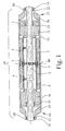
- the Coriolis measuring tube 1 is inside the compensation cylinder 6 arranged, and the Coriolis measuring tube 1 and the compensation cylinder 6 are mechanically connected to each other.
- the Coriolis measuring tube 1 and the Compensation cylinder 6 existing vibratory system including the Vibration generator 2, 3 and the transducer 4, 5, both for the excitation vibration of the Coriolis measuring tube 1 as well as for the Coriolis vibration of the Coriolis measuring tube 1 is at least largely balanced in terms of mass, ideally is completely balanced.
- balanced is meant that neither the excitation vibration nor the Coriolis vibration outside of that Coriolis measuring tube 1, the vibration generator 2, 3, the transducers 4, 5 and “affects” the compensation cylinder 6 comprising unit.
- the mass flow meters explained at the beginning which normally work according to the Coriolis principle problems with only a straight Coriolis measuring tube do not occur.
- Mass flow meter is the mass compensation for the excitation vibration of the Coriolis measuring tube 1 by a first compensation measure and the mass compensation for the Coriolis vibration of the Coriolis measuring tube 1 by a second, different from the first compensatory measure Compensation measure implemented. How this is implemented in detail is described below explains:
- a first balancing mass 7 is provided and in the - vertical to the longitudinal axis L - the central plane M of the compensation cylinder 6 associated with this.
- the first balancing mass 7 is selected, dimensioned and arranged that the resonance frequency of the compensation cylinder 6 and first Compensating mass 7 is significantly lower than the resonance frequency of the Coriolis measuring tube 1.
- the wall thickness of the Coriolis measuring tube is 1 relatively low. It can, for example, with a certain size of the invention Mass flow meter be about 1 mm. If the following dimensions are made, they apply to a mass flow meter according to the invention, in which the wall thickness of the Coriolis measuring tube is approximately 1 mm.
- the first balancing mass in the illustrated embodiment 7 is the first balancing mass in the illustrated embodiment 7 as a compensation cylinder arranged concentrically to the compensation cylinder 6 executed over a substantial part of the length of the Compensation cylinder 6 extends.
- the wall thickness of the compensation cylinder 6 is greater than the wall thickness of the Coriolis measuring tube 1, preferably about 3 to 5 mm, in particular is about 4 mm, and that the wall thickness realized as a compensating cylinder first balancing mass 7 is greater than the wall thickness of the compensation cylinder 6, preferably about three to ten times, in particular about that is five times the wall thickness of the compensation cylinder 6.
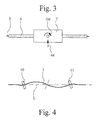
- FIGS. 1 and 2 of an inventive Mass flow meter is a special measure with considerable importance realized, which is characterized in that the first balancing mass 7 in relation to the excitation force AK shown in sketch form in FIG. 3 stiff with respect to that resulting from the Coriolis force - shown sketchily in FIG. 3 Coriolis moment CM, however, softly connected to the compensation cylinder 6 is.
- the connection of the first balancing mass 7 with the compensation cylinder 6 is so designed that the excitation vibration of the Coriolis measuring tube 1 acts on the first balancing mass 7, the Coriolis vibration of the Coriolis measuring tube 1, however, not, at least not significantly, to the first leveling compound 7 can act.
- connection of the first balancing mass with the compensation cylinder could also z. B. on leaf springs that are rigid in their main plane, perpendicular to their main level, however, are relatively soft. This connection is also conceivable with the help of thin rods, e.g. B. made of titanium.
- FIG. 1 and 2 show, are in the illustrated embodiment of an inventive Mass flow meter - as a mass compensation measure for the Coriolis vibration - a second balancing mass 10 and a third Leveling compound 11 present, the second leveling compound 10 and the third Compensating mass 11 is formed as end areas of the compensation cylinder 6 are.
- the second balancing mass 10 and the third Compensating mass 11 to Compensation cylinder 6 belong, you could the illustrated embodiment also describe in that in addition to the compensation cylinder 6 second balancing mass 10 and the third balancing mass 11 are present and the second balancing mass 10 and the third balancing mass 11 with the compensation cylinder 6 are connected. In the following, however, it should be the one chosen first Consideration remain.
- the second balancing mass now applies 10 and the third balancing mass 11 have a wall thickness that is essential is greater than the wall thickness of the compensation cylinder 6, more preferably five to ten times, especially about seven times the wall thickness of Compensation cylinder 6 is otherwise. It also applies that the length of the second Leveling compound 10 and the length of the third balancing compound 11 each about 5 up to 30%, in particular about 17 to 20% of the length of the compensation cylinder 6 overall, ie including the second balancing mass 10 and the third balancing mass 11, is.
- the Coriolis measuring tube 1, the vibration generator 2, 3, the transducers 4, 5 and the compensation cylinder 6 represent a unit.
- the compensation cylinder 6 at the end of the second balancing mass 10 and at the end of the third balancing mass 11 each via a connecting ring 12, 13 connected to the Coriolis measuring tube 1.
- the connecting rings are preferably 12, 13 connected by brazing to the Coriolis measuring tube 1 and is the compensation cylinder 6 at the end of the second balancing mass 10 and at the end of the third Leveling compound 11 by brazing or by shrinking with the connecting rings 12, 13 connected.
- both the vibrators are now 2, 3 and the transducers 4, 5 between the Coriolis measuring tube 1 and the compensation cylinder 6 is provided.
- part of the vibration generator 2, 3 and part of the Transducers 4, 5 with the Coriolis measuring tube and the other part of the Vibration generator 2, 3 and the transducer 4, 5 with the compensation cylinder 6 connected.
- vibration generator 2, 3 and as sensor 4, 5 Embodiments known in the art can be used that further explanations are not necessary.
- the vibrators 2, 3 can act both directly and indirectly on the Coriolis measuring tube 1.
- the distance between each transducer 4, 5 and the center plane M of the compensation cylinder 6 is different from the distance between each transducer 4, 5 and respective end of the compensation cylinder 6, ie the respective end of the second Balancing mass 10 and the third balancing mass 11.
- Mass flow meter also includes an outer housing 14.
- Housing 14 is the structural unit from the Coriolis measuring tube 1, the vibration generator 2, 3, the transducers 4, 5 and the compensation cylinder 6 mounted and fastened, in the exemplary embodiment over end regions of the Coriolis measuring tube 1, on both sides via the compensation cylinder 6, that is, via the second Compensating mass 10 and the third balancing mass 11, survive.
- the outer housing 14 as usual, consists of a circular cylindrical Housing jacket 15 and two housing end components 16, 17. It points each housing drain component 16 or 17 facing away from the housing jacket 15, approximately cylindrical end part 18 and a connecting part facing the housing jacket 15 19 on.
- the illustrated embodiment of a mass flow meter according to the invention is special in this respect with respect to the outer housing 14, as shown in FIG. 1 designed, on the one hand, the cylindrical end parts 18 of the housing end components 16, 17 only have the functionally necessary outer diameter and with one External thread 20 - for screwing on flanges, not shown here - provided are, on the other hand, the connecting parts 19 of the housing end components 16, 17 - in longitudinal section - have an approximately parallelogram-shaped cross section, the larger parallelogram axis between the housing shell 15 and the cylindrical end part 18 extends, and the cross-sectional area of the connecting parts 19th the housing end components 16, 17 is substantially larger than the cross-sectional area the cylindrical end portions 18.
- the mass flow meter according to the invention essentially symmetrical to the central plane M, previously also as the central plane M of the compensation cylinder 6 treated, is executed. Same thing for everyone Components, in particular also for the components realized according to the invention, that is to say for the first balancing mass 7, for the second balancing mass 10 and the third balancing mass 11, and for the housing end components 16, 17th
- FIG. 3 shows only the Coriolis measuring tube 1, the compensation cylinder 6 and the first balancing mass 7 indicated.
- those of - in 1 and 2 shown - vibration generators 2, 3 originating excitation force AK and the Coriolis moment resulting from the Coriolis force CM are indicated.
- the Sketch in Fig. 4 shows schematically only the Coriolis vibration of the Coriolis measuring tube 1.
- the Coriolis vibration of the Coriolis measuring tube 1 is natural the excitation vibration of the Coriolis measuring tube 1, not shown superimposed. 4 also indicates the second balancing mass 10 and the third balancing mass 11. It can be seen from the sketch in FIG.
Landscapes
- Physics & Mathematics (AREA)
- Fluid Mechanics (AREA)
- General Physics & Mathematics (AREA)
- Measuring Volume Flow (AREA)
- Other Investigation Or Analysis Of Materials By Electrical Means (AREA)
Description
- Fig. 1
- einen Längsschnitt durch ein bevorzugtes Ausführungsbeispiel eines erfindungsgemäßen Massendurchflußmeßgerätes,
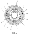
- Fig. 2
- einen Querschnitt durch das Massendurchflußmeßgerät nach Fig. 1, und zwar durch die Mittelebene M,
- Fig. 3
- eine Skizze zur Erläuterung des in den Fig. 1 und 2 dargestellten Ausführungsbeispiels eines erfindungsgemäßen Massendurchflußmeßgerätes und
- Fig. 4
- wiederum eine Skizze zur Erläuterung des in den Fig. 1 und 2 dargestellten Ausführungsbeispiels eines erfindungsgemäßen Massendurchflußmeßgerätes.
Claims (24)
- Massendurchflußmeßgerät, das nach dem Coriolis-Prinzip arbeitet, mit einem ein strömendes Medium führenden, im wesentlichen geraden Coriolis-Meßrohr (1), mit mindestens einem dem Coriolis-Meßrohr (1) zugeordneten, das Coriolis-Meßrohr (1) anregenden Schwingungserzeuger (2, 3), mit mindestens einem dem Coriolis-Meßrohr (1) zugeordneten, Coriolis-Kräfte und/oder auf Coriolis-Kräften beruhende Coriolis-Schwingungen erfassenden Meßwertaufnehmer (4, 5) und mit einem Kompensationszylinder (6), wobei das Coriolis-Meßrohr (1) innerhalb des Kompensationszylinders (6) angeordnet ist, der Kompensationszylinder (6) an seinen beiden Enden mechanisch mit dem Coriolis-Meßrohr verbunden ist und als massenmäßige Ausgleichsmaßnahme für die Anregungs-Schwingung eine erste Ausgleichsmasse (7) vorgesehen und in der senkrecht zur Längsachse (L) stehenden Mittelebene (M) des Kompensationszylinders (6) mit diesem verbunden ist, dadurch gekennzeichnet, daß als massenmäßige Ausgleichsmaßnahme für die Coriolis-Schwingung eine zweite Ausgleichsmasse (10) und eine dritte Ausgleichsmasse (11) vorgesehen sind und die zweite Ausgleichsmasse (10) und die dritte Ausgleichsmasse (11) als endseitige Bereiche des Kompensationszylinders ausgebildet sind, so daß das aus dem Coriolis-Meßrohr (1) und dem Kompensationszylinder (6) bestehende schwingungsfähige System sowohl für die Anregungs-Schwingung des Coriolis-Meßrohrs (1) als auch für die Coriolis-Schwingung des Coriolis-Meßrohrs (1) massenmäßig zumindest weitgehend ausgeglichen ist.
- Massendurchflußmeßgerät nach Anspruch 1, dadurch gekennzeichnet, daß die Resonanzfrequenz von Kompensationszylinder (6) und erster Ausgleichsmasse (7) wesentlich geringer ist als die Resonanzfrequenz des Coriolis-Meßrohres (1).
- Massendurchflußmeßgerät nach Anspruch 1 oder 2, dadurch gekennzeichnet, daß die Wandstärke des Coriolis-Meßrohres (1) relativ gering ist, vorzugsweise nur etwa 1 mm beträgt.
- Massendurchflußmeßgerät nach Anspruch 1 oder 3, dadurch gekennzeichnet, daß die erste Ausgleichsmasse (7) als konzentrisch zum Kompensationszylinder (6) angeordneter Ausgleichszylinder ausgeführt ist.
- Massendurchflußmeßgerät nach Anspruch 4, dadurch gekennzeichnet, daß sich die als Ausgleichszylinder ausgeführte erste Ausgleichsmasse (7) über einen wesentlichen Teil der Länge des Kompensationszylinders (6) erstreckt.
- Massendurchflußmeßgerät nach Anspruch 4 oder 5, dadurch gekennzeichnet, daß die Wandstärke des Kompensationszylinders (6) größer ist als die Wandstärke des Coriolis-Meßrohres (1), vorzugsweise etwa 3 bis 5 mm, insbesondere etwa 4 mm beträgt.
- Massendurchflußmeßgerät nach einem der Ansprüche 4 bis 6, dadurch gekennzeichnet, daß die Wandstärke der als Ausgleichszylinder ausgeführten ersten Ausgleichsmasse (7) größer ist als die Wandstärke des Kompensationszylinders (6), vorzugsweise etwa das drei- bis zehnfache, insbesondere etwa das fünffache der Wandstärke des Kompensationszylinders (6) beträgt.
- Massendurchflußmeßgeräte nach einem der Ansprüche 1 bis 7, dadurch gekennzeichnet, daß die erste Ausgleichsmasse in bezug auf die Anregungs-Kraft (AK) steif, in bezug auf das aus der Coriolis-Kraft resultierende Coriolis-Moment (CM) jedoch weich mit dem Kompensationszylinder (6) verbunden ist.
- Massendurchflußmeßgerät nach einem der Ansprüche 1 bis 8, dadurch gekennzeichnet, daß die zweite Ausgleichsmasse (10) und die dritte Ausgleichsmasse (11) eine Wandstärke haben, die wesentlich größer ist als die Wandstärke des Kompensationszylinders (6) im übrigen, vorzugsweise etwa das fünf- bis zehnfache, insbesondere etwa das siebenfache der Wandstärke des Kompensationszylinders (6) im übrigen beträgt.
- Massendurchflußmeßgerät nach einem der Ansprüche 1 bis 9, dadurch gekennzeichnet, daß die Länge der zweiten Ausgleichsmasse (10) und die Länge der dritten Ausgleichsmasse (11) jeweils etwa 15 bis 25 %, insbesondere etwa 17 bis 20 % der Länge des Kompensationszylinders insgesamt beträgt.
- Massendurchflußmeßgerät nach einem der Ansprüche 1 bis 10, dadurch gekennzeichnet, daß der Kompensationszylinder (6) am Ende der zweiten Ausgleichsmasse (10) und am Ende der dritten Ausgleichsmasse (11) jeweils über einen Verbindungsring (12, 13) mit dem Coriolis-Meßrohr (1) verbunden ist.
- Massendurchflußmeßgerät nach Anspruch 11, dadurch gekennzeichnet, daß die Verbindungsringe (12, 13) durch Hartlöten mit dem Coriolis-Meßrohr (1) verbunden sind.
- Massendurchflußmeßgerät nach Anspruch 11 oder 12, dadurch gekennzeichnet, daß der Kompensationszylinder (6) am Ende der zweiten Ausgleichsmasse (10) und am Ende der dritten Ausgleichsmasse (11) durch Hartlöten oder durch Schrumpfen mit den Verbindungsringen (12, 13) verbunden ist.
- Massendurchflußmeßgerät nach einem der Ansprüche 1 bis 13, dadurch gekennzeichnet, daß der Schwingungserzeuger bzw. die Schwingungserzeuger (2, 3) zwischen dem Coriolis-Meßrohr (1) und dem Kompensationszylinder (6) vorgesehen ist bzw. sind.
- Massendurchflußmeßgerät nach einem der Ansprüche 1 bis 14, dadurch gekennzeichnet, daß der Meßwertaufnehmer bzw. die Meßwertaufnehmer (4, 5) zwischen dem Coriolis-Meßrohr (1) und dem Kompensationszylinder (6) vorgesehen ist bzw. sind.
- Massendurchflußmeßgerät nach einem der Ansprüche 1 bis 15 mit zwei Meßwertaufnehmern (4, 5), dadurch gekennzeichnet, daß der Abstand zwischen jedem Meßwertaufnehmer (4, 5) und der Mittelebene (M) des Kompensationszylinders (6) unterschiedlich zu dem Abstand zwischen jedem Meßwertaufnehmer (4, 5) und dem jeweiligen Ende des Kompensationszylinders (6), also dem jeweiligen Ende der zweiten Ausgleichsmasse (10) und der dritten Ausgleichsmasse (13), ist.
- Massendurchflußmeßgerät nach einem der Ansprüche 1 bis 16 mit einem äußeren Gehäuse (14), dadurch gekennzeichnet, daß die Baueinheit aus dem Coriolis-Meßrohr (1) und dem Kompensationszylinder (6) über die Enden des Coriolis-Meßrohres (1) oder über besondere Anschlußrohre in dem Gehäuse (14) gelagert und befestigt ist.
- Massendurchflußmeßgerät nach Anspruch 17, dadurch gekennzeichnet, daß die Enden des Coriolis-Meßrohres (1) oder die besonderen Anschlußrohre jeweils über einen Verbindungsring (21, 22) an das Gehäuse (14) angeschlossen sind.
- Massendurchflußmeßgerät nach einem der Ansprüche 1 bis 16 mit einem äußeren Gehäuse oder nach Anspruch 20 oder 21, dadurch gekennzeichnet, daß das Gehäuse (14) aus einem vorzugsweise kreiszylindrischen Gehäusemantel (15) und aus zwei Gehäuseabschlußbauteilen (16, 17) besteht.
- Massendurchflußmeßgerät nach Anspruch 19, dadurch gekennzeichnet, daß jedes Gehäuseabschlußbauteil (16, 17) ein dem Gehäusemantel (15) abgewandtes, zumindest etwa zylindrisches Endteil (18) und ein dem Gehäusemantel (15) zugewandtes Verbindungsteil (19) aufweist.
- Massendurchflußmeßgerät nach Anspruch 20, dadurch gekennzeichnet, daß die zylindrischen Endteile (18) der Gehäuseabschlußbauteile (16, 17) nur den funktionsnotwendigen Außendurchmesser haben.
- Massendurchflußmeßgerät nach Anspruch 21, dadurch gekennzeichnet, daß die zylindrischen Endteile (18) der Gehäuseabschlußbauteile (16, 17) mit einem Außengewinde (20) versehen sind.
- Massendurchflußmeßgerät nach einem der Ansprüche 20 bis 22, dadurch gekennzeichnet, daß die Verbindungsstelle (19) der Gehäuseabschlußbauteile (16, 17) - im Längsschnitt - einen zumindest etwa parallelogrammförmigen Querschnitt aufweisen, wobei die größere Parallelogrammachse zwischen dem Gehäusemantel (15) und dem Endteil (18) verläuft.
- Massendurchflußmeßgerät nach Anspruch 23, dadurch gekennzeichnet, daß die Querschnittsfläche der Verbindungsteile (19) der Gehäuseabschlußbauteile (16, 17) wesentlich größer ist als die Querschnittsfläche der Endteile (18).
Applications Claiming Priority (2)
| Application Number | Priority Date | Filing Date | Title |
|---|---|---|---|
| DE19908072A DE19908072C2 (de) | 1999-02-12 | 1999-02-12 | Massendurchflußmeßgerät |
| DE19908072 | 1999-02-12 |
Publications (2)
| Publication Number | Publication Date |
|---|---|
| EP1028310A1 EP1028310A1 (de) | 2000-08-16 |
| EP1028310B1 true EP1028310B1 (de) | 2002-10-16 |
Family
ID=7898772
Family Applications (1)
| Application Number | Title | Priority Date | Filing Date |
|---|---|---|---|
| EP00102557A Expired - Lifetime EP1028310B1 (de) | 1999-02-12 | 2000-02-07 | Massendurchflussmessgerät |
Country Status (6)
| Country | Link |
|---|---|
| US (1) | US6397685B1 (de) |
| EP (1) | EP1028310B1 (de) |
| JP (1) | JP3746180B2 (de) |
| AT (1) | ATE226316T1 (de) |
| DE (2) | DE19908072C2 (de) |
| DK (1) | DK1028310T3 (de) |
Families Citing this family (43)
| Publication number | Priority date | Publication date | Assignee | Title |
|---|---|---|---|---|
| US6691583B2 (en) * | 2001-04-24 | 2004-02-17 | Endress + Hauser Flowtec Ag | Vibratory transducer |
| DE10220734C1 (de) * | 2002-03-06 | 2003-04-24 | Krohne Ag Basel | Massendurchflußmeßgerät |
| WO2003095950A1 (de) * | 2002-05-08 | 2003-11-20 | Endress + Hauser Flowtec Ag | Messwandler vom vibrationstyp |
| US7579681B2 (en) * | 2002-06-11 | 2009-08-25 | Micron Technology, Inc. | Super high density module with integrated wafer level packages |
| DE10258962B4 (de) * | 2002-12-16 | 2005-09-22 | Krohne Ag | Massendurchflußmeßgerät und Verfahren zur Korrektur des Meßsingals eines Massendurchflußmeßgeräts |
| RU2316734C2 (ru) * | 2003-04-17 | 2008-02-10 | Майкро Моушн, Инк. | Способ и устройство для силового уравновешивания расходомера кориолиса |
| BRPI0318248B1 (pt) | 2003-04-17 | 2018-12-11 | Micro Motion Inc | método e aparelho para o equilíbrio de forças em um medidor de vazão do tipo coriolis |
| DE10351311B3 (de) * | 2003-10-31 | 2005-06-30 | Abb Patent Gmbh | Coriolis-Massendurchflussmessgerät |
| DE10354373A1 (de) * | 2003-11-20 | 2005-06-16 | Endress + Hauser Flowtec Ag, Reinach | Messaufnehmer vom Vibrationstyp |
| WO2006089855A1 (de) | 2005-02-25 | 2006-08-31 | Endress+Hauser Flowtec Ag | Messaufnehmer vom vibrationstyp |
| US7475603B2 (en) | 2005-11-15 | 2009-01-13 | Endress + Hauser Flowtec Ag | Measurement transducer of vibration-type |
| US7490521B2 (en) * | 2005-11-15 | 2009-02-17 | Endress + Hauser Flowtec Ag | Measurement transducer of vibration type |
| US7472607B2 (en) * | 2005-11-15 | 2009-01-06 | Endress + Hauser Flowtec Ag | Measurement transducer of vibration type |
| US7631561B2 (en) * | 2006-03-22 | 2009-12-15 | Endress + Hauser Flowtec Ag | Measuring transducer of vibration-type |
| US7555962B2 (en) * | 2006-03-22 | 2009-07-07 | Endress + Hauser Flowtec Ag | Measuring transducer of vibration-type |
| US7546777B2 (en) * | 2006-03-22 | 2009-06-16 | Endress + Hauser Flowtec Ag | Measuring transducer of vibration-type |
| DE102006013601A1 (de) | 2006-03-22 | 2007-09-27 | Endress + Hauser Flowtec Ag | Meßaufnehmer vom Vibrationstyp |
| DE102007050686A1 (de) | 2007-10-22 | 2009-04-23 | Endress + Hauser Flowtec Ag | Meßwandler vom Vibrationstyp |
| DE102007062397A1 (de) | 2007-12-20 | 2009-06-25 | Endress + Hauser Flowtec Ag | Meßwandler vom Vibrationstyp |
| EP2252865B1 (de) * | 2008-02-20 | 2020-09-30 | Micro Motion, Inc. | Durchflussmesser vom vibrationstyp und verfahren zur austarierung eines durchflussmessers vom vibrationstyp |
| DE102008035877A1 (de) | 2008-08-01 | 2010-02-04 | Endress + Hauser Flowtec Ag | Meßwandler vom Vibrationstyp |
| DE102008050115A1 (de) | 2008-10-06 | 2010-04-08 | Endress + Hauser Flowtec Ag | In-Line-Meßgerät |
| DE102008050113A1 (de) | 2008-10-06 | 2010-04-08 | Endress + Hauser Flowtec Ag | In-Line-Meßgerät |
| DE102008050116A1 (de) | 2008-10-06 | 2010-04-08 | Endress + Hauser Flowtec Ag | In-Line-Meßgerät |
| DE102008044186A1 (de) | 2008-11-28 | 2010-06-02 | Endress + Hauser Flowtec Ag | Magneteinrichtung sowie Meßaufnehmer vom Vibrationstyp mit einer solchen Magneteinrichtung |
| NL1036341C2 (nl) * | 2008-12-19 | 2010-06-22 | Berkin Bv | Coriolis flowsensor met verend opgehangen balansmassa. |
| DE102009012474A1 (de) | 2009-03-12 | 2010-09-16 | Endress + Hauser Flowtec Ag | Meßsystem mit einem Messwandler vom Vibrationstyp |
| DE102009028006A1 (de) | 2009-07-24 | 2011-01-27 | Endress + Hauser Flowtec Ag | Meßwandler vom Vibrationstyp sowie Meßgerät mit einem solchen Meßwandler |
| DE102009028007A1 (de) | 2009-07-24 | 2011-01-27 | Endress + Hauser Flowtec Ag | Meßumwandler vom Vibrationstyp sowie Meßgerät mit einem solchen Meßwandler |
| EP2519804B1 (de) | 2009-12-31 | 2019-08-28 | Endress+Hauser Flowtec AG | Mess-system mit einem messwandler vom vibrationstyp |
| CA2785919C (en) | 2009-12-31 | 2016-05-24 | Endress+Hauser Flowtec Ag | Measuring system having a measuring transducer of vibration-type |
| DE102010000760B4 (de) | 2010-01-11 | 2021-12-23 | Endress + Hauser Flowtec Ag | Meßsystem mit einem Meßwandler vom Vibrationstyp zum Messen eines statischen Drucks in einem strömenden Medium |
| DE102010000759B4 (de) | 2010-01-11 | 2025-05-22 | Endress + Hauser Flowtec Ag | Meßsystem mit einem Meßwandler vom Vibrationstyp |
| CN102686985B (zh) | 2009-12-31 | 2015-04-01 | 恩德斯+豪斯流量技术股份有限公司 | 具有振动型测量转换器的测量系统 |
| DE102010000761A1 (de) | 2010-01-11 | 2011-07-28 | Endress + Hauser Flowtec Ag | Meßsystem mit einem Meßwandler vom Vibrationstyp |
| DE102010039543A1 (de) | 2010-08-19 | 2012-02-23 | Endress + Hauser Flowtec Ag | Meßsystem mit einem Meßwandler vom Vibrationstyp |
| DE102010044179A1 (de) | 2010-11-11 | 2012-05-16 | Endress + Hauser Flowtec Ag | Meßsystem mit einem Meßwandler von Vibrationstyp |
| US9080908B2 (en) | 2013-07-24 | 2015-07-14 | Jesse Yoder | Flowmeter design for large diameter pipes |
| NL2012498B1 (en) * | 2014-03-24 | 2016-01-19 | Berkin Bv | Coriolis flowsensor. |
| US20150153210A1 (en) * | 2013-12-04 | 2015-06-04 | Gilbarco Inc. | Fuel dispenser coriolis flow meter |
| US10782170B1 (en) | 2020-02-26 | 2020-09-22 | IDEX India PVT. LTD | Method and apparatus to balance a coriolis mass flow meter adding balancing weights by determining reaction forces |
| DE112021003296A5 (de) | 2020-06-18 | 2023-05-11 | Endress+Hauser Flowtec Ag | Vibronisches Meßsystem |
| DE102020131649A1 (de) | 2020-09-03 | 2022-03-03 | Endress + Hauser Flowtec Ag | Vibronisches Meßsystem |
Family Cites Families (21)
| Publication number | Priority date | Publication date | Assignee | Title |
|---|---|---|---|---|
| KR960000099B1 (ko) * | 1986-10-28 | 1996-01-03 | 더폭스보로 컴패니 | 코리올리 유형의 질량유량계 |
| US5271281A (en) * | 1986-10-28 | 1993-12-21 | The Foxboro Company | Coriolis-type mass flowmeter |
| DE4121732A1 (de) * | 1991-07-01 | 1993-01-07 | Rota Yokogawa Gmbh & Co Kg | Messgeraet zur erfassung eines massendurchflusses nach dem coriolis-prinzip |
| DE4143361A1 (de) * | 1991-07-22 | 1993-03-04 | Krohne Ag | Massendurchflussmessgeraet |
| DE4124295A1 (de) * | 1991-07-22 | 1993-01-28 | Krohne Ag | Massendurchflussmessgeraet |
| DE4224379C2 (de) * | 1992-07-06 | 1998-05-20 | Krohne Messtechnik Kg | Massendurchflußmeßgerät |
| DE4423168C2 (de) | 1994-07-04 | 1998-09-24 | Krohne Ag | Massendurchflußmeßgerät |
| JPH08247816A (ja) * | 1995-03-09 | 1996-09-27 | Fuji Electric Co Ltd | 質量流量計 |
| ES2232817T3 (es) * | 1995-08-21 | 2005-06-01 | Oval Corporation | Medidores de caudal tipo coriolis. |
| JP3058094B2 (ja) * | 1996-09-04 | 2000-07-04 | 富士電機株式会社 | 質量流量計 |
| GB2314930B (en) * | 1996-03-17 | 2000-03-08 | Krohne Ag | Mass flow measuring device |
| US5827979A (en) * | 1996-04-22 | 1998-10-27 | Direct Measurement Corporation | Signal processing apparati and methods for attenuating shifts in zero intercept attributable to a changing boundary condition in a Coriolis mass flow meter |
| US5954819A (en) * | 1996-05-17 | 1999-09-21 | National Semiconductor Corporation | Power conservation method and apparatus activated by detecting programmable signals indicative of system inactivity and excluding prefetched signals |
| DE19632500C2 (de) * | 1996-08-12 | 1999-10-28 | Krohne Ag Basel | Massendurchflußmeßgerät |
| US5796012A (en) * | 1996-09-19 | 1998-08-18 | Oval Corporation | Error correcting Coriolis flowmeter |
| FR2754597B1 (fr) * | 1996-10-15 | 1998-12-24 | Schlumberger Cie Dowell | Debitmetre fonde sur l'exploitation des forces de coriolis |
| DE59700185D1 (de) * | 1996-12-11 | 1999-07-08 | Flowtec Ag | Coriolis-Massendurchfluss-/-Dichte-Aufnehmer mit einem einzigen geraden Messrohr |
| US6158290A (en) * | 1997-04-11 | 2000-12-12 | Krohne A.G. | Mass flow meter |
| DE19825775A1 (de) * | 1997-10-07 | 1999-05-12 | Krohne Ag | Massendurchflußmeßgerät |
| JP2885768B1 (ja) * | 1997-10-22 | 1999-04-26 | 株式会社オーバル | コリオリ式質量流量計 |
| DE19840782C2 (de) * | 1998-09-08 | 2001-09-06 | Krohne Messtechnik Kg | Massendurchflußmeßgerät |
-
1999
- 1999-02-12 DE DE19908072A patent/DE19908072C2/de not_active Expired - Fee Related
-
2000
- 2000-02-07 US US09/499,182 patent/US6397685B1/en not_active Expired - Fee Related
- 2000-02-07 EP EP00102557A patent/EP1028310B1/de not_active Expired - Lifetime
- 2000-02-07 DK DK00102557T patent/DK1028310T3/da active
- 2000-02-07 DE DE50000628T patent/DE50000628D1/de not_active Expired - Lifetime
- 2000-02-07 AT AT00102557T patent/ATE226316T1/de not_active IP Right Cessation
- 2000-02-09 JP JP2000032219A patent/JP3746180B2/ja not_active Expired - Fee Related
Also Published As
| Publication number | Publication date |
|---|---|
| DE19908072A1 (de) | 2000-08-31 |
| DE50000628D1 (de) | 2002-11-21 |
| DK1028310T3 (da) | 2003-02-17 |
| JP2000234947A (ja) | 2000-08-29 |
| US6397685B1 (en) | 2002-06-04 |
| EP1028310A1 (de) | 2000-08-16 |
| ATE226316T1 (de) | 2002-11-15 |
| DE19908072C2 (de) | 2002-10-17 |
| JP3746180B2 (ja) | 2006-02-15 |
Similar Documents
| Publication | Publication Date | Title |
|---|---|---|
| DE19908072C2 (de) | Massendurchflußmeßgerät | |
| DE19840782C2 (de) | Massendurchflußmeßgerät | |
| DE19621365C2 (de) | Massendurchflußmeßgerät | |
| EP1208359B1 (de) | Verfahren zur bestimmung charakteristischer grössen eines massendurchflussmessgerätes während seines betriebs | |
| EP0547455B1 (de) | Massendurchflussmessgerät | |
| EP0524523B1 (de) | Massendurchflussmessgerät | |
| EP1798532B1 (de) | Coriolismassendurchflussmessgerät | |
| EP1528374B1 (de) | Coriolis-Massendurchflussmessgerät | |
| EP0775893B1 (de) | Massendurchflussmessgerät | |
| EP0578113B1 (de) | Massendurchflussmessgerät | |
| DE19710806C2 (de) | Massendurchflußmeßgerät | |
| DE19620079C2 (de) | Massendurchflußmeßgerät | |
| WO2003095950A1 (de) | Messwandler vom vibrationstyp | |
| EP0855017B1 (de) | Massendurchflussmessgerät | |
| EP1759178B1 (de) | Messwandler vom vibrationstyp | |
| EP3521774A1 (de) | Ultraschall-durchflussmessvorrichtung und verfahren zum bestimmen der strömungsgeschwindigkeit | |
| DE10220734C1 (de) | Massendurchflußmeßgerät | |
| DE4200060C2 (de) | Massendurchflußmeßgerät | |
| EP1949048B1 (de) | Messwandler vom vibrationstyp | |
| DE4417332A1 (de) | Massendurchflußmeßgerät | |
| EP1672331A1 (de) | Coriolis-Massendurchflussmessgerät | |
| DE102004026322B3 (de) | Coriolis-Massendurchflußmeßgerät | |
| EP1342995A2 (de) | Coriolis-Massendurchflussmesser mit schwingungsfreier Rohrleitungssystemkopplung | |
| DE102005034749A1 (de) | Coriolis-Massendurchflussmessgerät und Verfahren zur Herstellung eines Coriolis-Massendurchflussmessgeräts |
Legal Events
| Date | Code | Title | Description |
|---|---|---|---|
| PUAI | Public reference made under article 153(3) epc to a published international application that has entered the european phase |
Free format text: ORIGINAL CODE: 0009012 |
|
| AK | Designated contracting states |
Kind code of ref document: A1 Designated state(s): AT BE CH CY DE DK ES FI FR GB GR IE IT LI LU MC NL PT SE |
|
| AX | Request for extension of the european patent |
Free format text: AL;LT;LV;MK;RO;SI |
|
| 17P | Request for examination filed |
Effective date: 20001106 |
|
| AKX | Designation fees paid |
Free format text: AT BE CH CY DE DK ES FI FR GB GR IE IT LI LU MC NL PT SE |
|
| 17Q | First examination report despatched |
Effective date: 20010423 |
|
| GRAG | Despatch of communication of intention to grant |
Free format text: ORIGINAL CODE: EPIDOS AGRA |
|
| GRAG | Despatch of communication of intention to grant |
Free format text: ORIGINAL CODE: EPIDOS AGRA |
|
| GRAH | Despatch of communication of intention to grant a patent |
Free format text: ORIGINAL CODE: EPIDOS IGRA |
|
| GRAH | Despatch of communication of intention to grant a patent |
Free format text: ORIGINAL CODE: EPIDOS IGRA |
|
| GRAA | (expected) grant |
Free format text: ORIGINAL CODE: 0009210 |
|
| AK | Designated contracting states |
Kind code of ref document: B1 Designated state(s): AT BE CH CY DE DK ES FI FR GB GR IE IT LI LU MC NL PT SE |
|
| PG25 | Lapsed in a contracting state [announced via postgrant information from national office to epo] |
Ref country code: IT Free format text: LAPSE BECAUSE OF FAILURE TO SUBMIT A TRANSLATION OF THE DESCRIPTION OR TO PAY THE FEE WITHIN THE PRE;WARNING: LAPSES OF ITALIAN PATENTS WITH EFFECTIVE DATE BEFORE 2007 MAY HAVE OCCURRED AT ANY TIME BEFORE 2007. THE CORRECT EFFECTIVE DATE MAY BE DIFFERENT FROM THE ONE RECORDED.SCRIBED TIME-LIMIT Effective date: 20021016 Ref country code: NL Free format text: LAPSE BECAUSE OF FAILURE TO SUBMIT A TRANSLATION OF THE DESCRIPTION OR TO PAY THE FEE WITHIN THE PRESCRIBED TIME-LIMIT Effective date: 20021016 Ref country code: FI Free format text: LAPSE BECAUSE OF FAILURE TO SUBMIT A TRANSLATION OF THE DESCRIPTION OR TO PAY THE FEE WITHIN THE PRESCRIBED TIME-LIMIT Effective date: 20021016 Ref country code: IE Free format text: LAPSE BECAUSE OF FAILURE TO SUBMIT A TRANSLATION OF THE DESCRIPTION OR TO PAY THE FEE WITHIN THE PRESCRIBED TIME-LIMIT Effective date: 20021016 Ref country code: GR Free format text: LAPSE BECAUSE OF FAILURE TO SUBMIT A TRANSLATION OF THE DESCRIPTION OR TO PAY THE FEE WITHIN THE PRESCRIBED TIME-LIMIT Effective date: 20021016 |
|
| REF | Corresponds to: |
Ref document number: 226316 Country of ref document: AT Date of ref document: 20021115 Kind code of ref document: T |
|
| REG | Reference to a national code |
Ref country code: GB Ref legal event code: FG4D Free format text: NOT ENGLISH |
|
| REG | Reference to a national code |
Ref country code: CH Ref legal event code: EP |
|
| REG | Reference to a national code |
Ref country code: IE Ref legal event code: FG4D Free format text: GERMAN |
|
| REF | Corresponds to: |
Ref document number: 50000628 Country of ref document: DE Date of ref document: 20021121 |
|
| PG25 | Lapsed in a contracting state [announced via postgrant information from national office to epo] |
Ref country code: SE Free format text: LAPSE BECAUSE OF FAILURE TO SUBMIT A TRANSLATION OF THE DESCRIPTION OR TO PAY THE FEE WITHIN THE PRESCRIBED TIME-LIMIT Effective date: 20030116 Ref country code: PT Free format text: LAPSE BECAUSE OF FAILURE TO SUBMIT A TRANSLATION OF THE DESCRIPTION OR TO PAY THE FEE WITHIN THE PRESCRIBED TIME-LIMIT Effective date: 20030116 |
|
| PG25 | Lapsed in a contracting state [announced via postgrant information from national office to epo] |
Ref country code: AT Free format text: LAPSE BECAUSE OF NON-PAYMENT OF DUE FEES Effective date: 20030207 Ref country code: CY Free format text: LAPSE BECAUSE OF FAILURE TO SUBMIT A TRANSLATION OF THE DESCRIPTION OR TO PAY THE FEE WITHIN THE PRESCRIBED TIME-LIMIT Effective date: 20030207 Ref country code: LU Free format text: LAPSE BECAUSE OF NON-PAYMENT OF DUE FEES Effective date: 20030207 |
|
| REG | Reference to a national code |
Ref country code: CH Ref legal event code: NV Representative=s name: KELLER & PARTNER PATENTANWAELTE AG |
|
| REG | Reference to a national code |
Ref country code: DK Ref legal event code: T3 |
|
| PG25 | Lapsed in a contracting state [announced via postgrant information from national office to epo] |
Ref country code: BE Free format text: LAPSE BECAUSE OF NON-PAYMENT OF DUE FEES Effective date: 20030228 Ref country code: MC Free format text: LAPSE BECAUSE OF NON-PAYMENT OF DUE FEES Effective date: 20030228 |
|
| GBT | Gb: translation of ep patent filed (gb section 77(6)(a)/1977) |
Effective date: 20030213 |
|
| NLV1 | Nl: lapsed or annulled due to failure to fulfill the requirements of art. 29p and 29m of the patents act | ||
| PG25 | Lapsed in a contracting state [announced via postgrant information from national office to epo] |
Ref country code: ES Free format text: LAPSE BECAUSE OF FAILURE TO SUBMIT A TRANSLATION OF THE DESCRIPTION OR TO PAY THE FEE WITHIN THE PRESCRIBED TIME-LIMIT Effective date: 20030429 |
|
| ET | Fr: translation filed | ||
| REG | Reference to a national code |
Ref country code: IE Ref legal event code: FD4D Ref document number: 1028310E Country of ref document: IE |
|
| PLBE | No opposition filed within time limit |
Free format text: ORIGINAL CODE: 0009261 |
|
| STAA | Information on the status of an ep patent application or granted ep patent |
Free format text: STATUS: NO OPPOSITION FILED WITHIN TIME LIMIT |
|
| 26N | No opposition filed |
Effective date: 20030717 |
|
| PGFP | Annual fee paid to national office [announced via postgrant information from national office to epo] |
Ref country code: FR Payment date: 20120227 Year of fee payment: 13 Ref country code: CH Payment date: 20120221 Year of fee payment: 13 |
|
| PGFP | Annual fee paid to national office [announced via postgrant information from national office to epo] |
Ref country code: GB Payment date: 20120221 Year of fee payment: 13 Ref country code: DK Payment date: 20120217 Year of fee payment: 13 |
|
| PGFP | Annual fee paid to national office [announced via postgrant information from national office to epo] |
Ref country code: DE Payment date: 20120428 Year of fee payment: 13 |
|
| REG | Reference to a national code |
Ref country code: DK Ref legal event code: EBP |
|
| REG | Reference to a national code |
Ref country code: CH Ref legal event code: PL |
|
| GBPC | Gb: european patent ceased through non-payment of renewal fee |
Effective date: 20130207 |
|
| PG25 | Lapsed in a contracting state [announced via postgrant information from national office to epo] |
Ref country code: LI Free format text: LAPSE BECAUSE OF NON-PAYMENT OF DUE FEES Effective date: 20130228 Ref country code: CH Free format text: LAPSE BECAUSE OF NON-PAYMENT OF DUE FEES Effective date: 20130228 |
|
| REG | Reference to a national code |
Ref country code: FR Ref legal event code: ST Effective date: 20131031 |
|
| REG | Reference to a national code |
Ref country code: DE Ref legal event code: R119 Ref document number: 50000628 Country of ref document: DE Effective date: 20130903 |
|
| PG25 | Lapsed in a contracting state [announced via postgrant information from national office to epo] |
Ref country code: FR Free format text: LAPSE BECAUSE OF NON-PAYMENT OF DUE FEES Effective date: 20130228 Ref country code: DK Free format text: LAPSE BECAUSE OF NON-PAYMENT OF DUE FEES Effective date: 20130228 Ref country code: DE Free format text: LAPSE BECAUSE OF NON-PAYMENT OF DUE FEES Effective date: 20130903 Ref country code: GB Free format text: LAPSE BECAUSE OF NON-PAYMENT OF DUE FEES Effective date: 20130207 |